


Grænsen mellem den optiske medie og koaksialkablet er den optiske modtager. I denne artikel vil vi se nærmere på deres konstruktion og indstillinger.
Indhold af artikelserien
- Del 7: Optiske modtagere
- Del 8: Optisk hovednetværk
- Del 9: Hovedstation
- Del 10: Fejlfinding på KTV-netværket
Formålet med den optiske modtager er at overføre signalet fra den optiske medie til elektrisk. I sin simpleste form kan dette gøres med en passiv enhed, der imponerer med sin enkelhed:
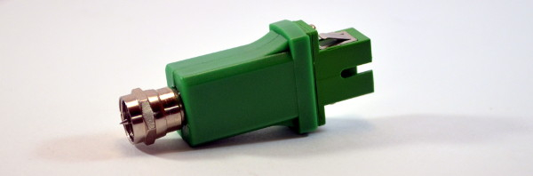
Men dette ingeniørvidunder giver faktisk ganske middelmådige signalparametre: når det optiske signal er på -1 til -2 dBm, er udgangsparametrene kun lige inden for standarden, og en forstærkning af signalet fører til betydelig støj.
For at sikre kvaliteten af det leverede signal kræves der i FTTB-arkitektur mere komplekse enheder:

Modtagerne, der findes i vores netværk: Vector Lambda, Telmor MOB og den lokale Planar.
I forhold til deres passive mindre søskende adskiller de sig alle med mere kompleks kredsløbsdesign, der inkluderer filtre og forstærkere, hvilket gør, at man kan være tryg ved signalet, der når frem til abonnenten. Lad os se nærmere på dem:
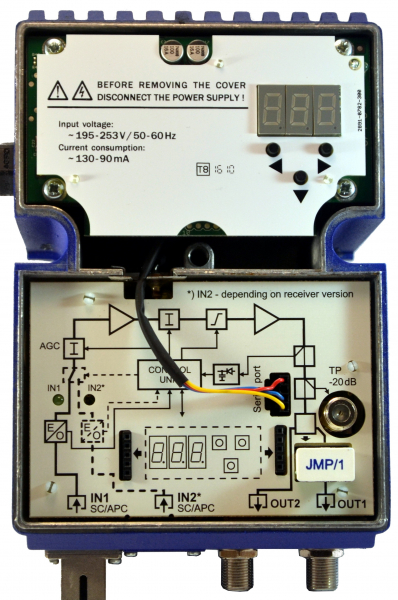
Den optiske modtager Telmor har et panel med en illustration af den strukturelle skematik indvendigt. Sådan en skematik er typisk for OPM.
Det krævede niveau for det optiske signal ligger som regel mellem -10 og +3 dBm, og ved design og idriftsættelse er det optimale værdi -1 dBm: dette giver en god margin i tilfælde af degradering af transmissionslinjen, og samtidig skaber et lavt niveau mindre støj i udstyrets kredsløb.
Den indbyggede AGC-skema (Automatic Gain Control) i den optiske modtager har til opgave at holde udgangsniveauet inden for de fastsatte parametre ved at regulere niveauet for det indkommende signal. Dette betyder, at hvis det optiske signal pludselig ændrer sig betydeligt af en eller anden grund, men forbliver inden for AGC's arbejdsområde (ca. fra 0 til -7 dBm), vil modtageren korrekt returnere signalet med det niveau, der blev indstillet under opsætning. For særligt vigtige tilfælde findes der enheder med to optiske indgange, hvor hver enkelt overvåges og kan aktiveres både manuelt og automatisk.
Alle aktive OPM'er indeholder en forstærkningscascade, som også giver mulighed for justering af hældning og niveau for udgangssignalet.
Styring af optiske modtagere
For adjusting signal parameters, as well as modifying and controlling the built-in service functions within the receivers, there are usually simple control devices. In the MOB shown in the photo above, this is a separate board that can be optionally installed into the housing. Alternatively, a quick-release board is offered, which is installed only for the duration of the setup in the ports on the main board. In practice, this is not very convenient, of course.
The control panel allows you to set the values of the input attenuator (where increasing it decreases the output signal according to the gain ratio), turn the AGC on or off (as well as setting fixed values), adjust the slope parameters, and configure the ethernet interface.
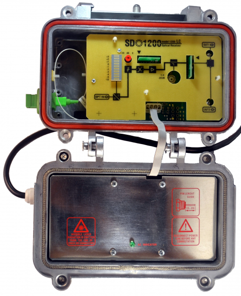
The Chelyabinsk OP Planar has a clear optical signal level indicator, and adjustments are made simply: with a knob and by changing inserts that alter the characteristics of the amplifier stage. The power supply unit is located in the folding cover.
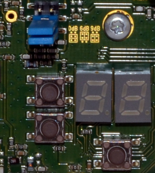
The OP Vector Lambda, designed in a 'techno-porn' style, features a two-digit display and only three buttons.
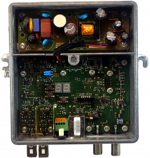
To differentiate positive values from negative ones, this OP displays negative values across all segments, while positive zero and +1 shows at half the screen height. For values exceeding +1.9, it simply writes 'HI'.
Such control devices are convenient for on-site adjustments, but for remote monitoring and control, almost all receivers have an ethernet port. The web interface allows you to control and change parameters, and for integration with monitoring systems, SNMP polling is supported.
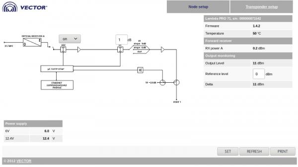
Here we see the same typical structural diagram of the OP, which allows for the adjustment of AGC and attenuator parameters. However, the slope on this OP is set only by jumpers on the board and has three fixed positions.
Next to the diagram, important control parameters are displayed: levels of incoming and outgoing signals, as well as voltage values obtained from the built-in power supply unit. 99% of failures of such OPs occur after deterioration of these voltages, so it is worth monitoring them to prevent emergencies.
Under the term Transponder, we mean the IP interface, and this tab contains settings for the address, mask, and gateway — nothing particularly interesting.
Bonus: terrestrial television reception
This is not related to the theme of the series, but I will briefly mention terrestrial TV reception. Why now? Because when considering the network of an apartment building, it is actually the signal source in the coaxial distribution network that determines whether the network will be cable or terrestrial.
In the absence of fiber optic, a terrestrial broadcasting receiver, such as the Terra MA201, can be installed instead of the OPP:
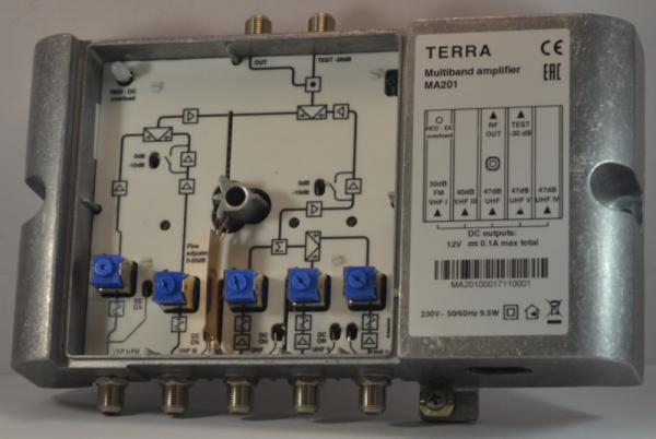
Several antennas (usually three) are connected to the input ports of the receiver, each of which provides reception for its frequency range.
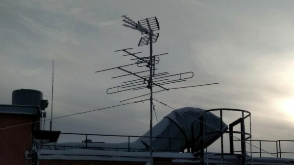
Actually, with the transition to digital broadcasting, this becomes unnecessary, as digital multiplexes are broadcast in a single range.
For each of the antennas, sensitivity can be adjusted to reduce noise, and if necessary, remote power can be supplied to the amplifier built into the antenna. The signal then goes through an amplification cascade and is summed. Adjusting the output level is limited to turning off the steps of the cascade, and tilt adjustment is not provided at all: the desired spectrum shape can be achieved by adjusting the sensitivity of each antenna individually. If there are kilometers of coaxial cable behind such a receiver, then attenuation is dealt with by installing and adjusting amplifiers, similar to those used in cable networks.
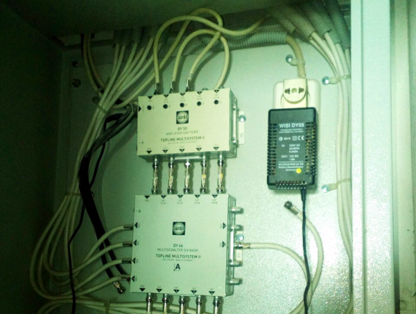
If desired, signal sources can be combined: integrating both cable and terrestrial signals into one network, and also adding satellite signals. This is done using multiswitches — devices that allow signals from different sources to be summed and distributed.
Kilde: habr.com
