

After a year of development, the release of the open-source PCB design automation system KiCad 8.0.0 has been published. This is the second significant release since the project came under the Linux Foundation's umbrella. Builds are available for various Linux distributions, Windows, and macOS. The code is written in C++ using the wxWidgets library and is distributed under the GPLv3 license.
KiCad provides tools for editing electrical schematics and printed circuit boards, 3D visualization of boards, working with electrical circuit element libraries, manipulating Gerber-format templates, simulating electronic circuit operations, editing printed circuit boards, and project management. The project also provides libraries of electronic components, footprints, and 3D models. According to some printed circuit board manufacturers, about 15% of orders are received with schematics prepared in KiCad.
Among the changes in the new release:
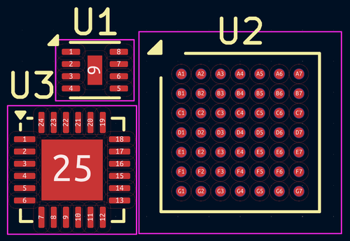
- Official footprint libraries have been expanded, adding over 1500 new symbols and 760 footprints. Eight new libraries have been included. A new intuitive pin indication style has been implemented and is used in the footprint generators. Some automatically generated components in SMD packages have already adopted the new style.

- The capabilities for importing and transferring data from other packages have been expanded. Support has been added for importing projects and libraries from the EasyEDA environment (JLCEDA), board layouts from Solidworks CAD, symbol libraries from EAGLE, schematics from LTSpice, and symbol and footprint libraries from CADSTAR and Altium Designer. The PCB editor now allows for the adjustment of spacing between line segments in drawings imported from other CAD systems, simplifying the import of contours, zones, and complex shapes. The schematic and symbol editors have added support for importing vector graphics in DXF and SVG formats.

- The PCB editor now supports exporting in IPC-2581 format, allowing the creation of a single package with data for PCB manufacturing and assembly. An option has been introduced for saving copper shapes along with the board geometry data during STEP export for more accurate electromagnetic interaction simulation. The schematic editor has added the ability to export a bill of materials (BOM) in Cadence Allegro format.
- The command line interface now supports DRC (Design Rules Checker) and ERC (Electrical Rules Checker) checks, with output results in JSON format. The ability to export lists of components (BOM) and 3D models in glTF and VRML formats has been implemented. Support for overriding text variables and drawing sheets has been added. There is now the option to control the layer stacking order for multilayer boards.
- The ability to assign alternative keyboard shortcuts for invoking any actions has been added.
- In library editors, hovering over a name in the list now shows previews of characters and footprints.
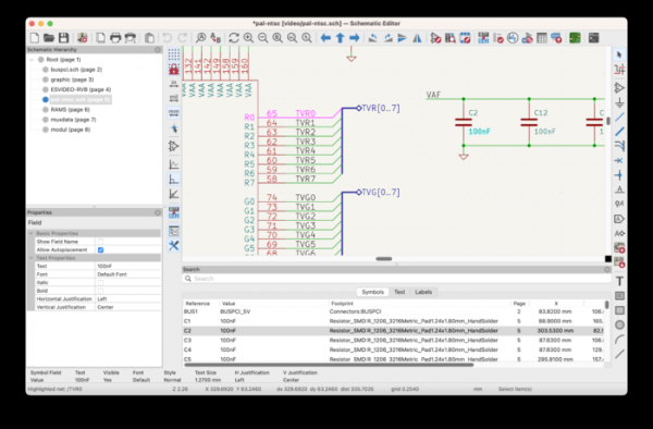
- New side panels have been added in the schematic editor for quick editing of the selected element's properties, visual navigation through circuits, and for searching elements in the schematic.

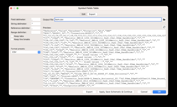
- A new interface for exporting the Bill of Materials (BOM) has been added, allowing customization of which data will be saved and in what format.

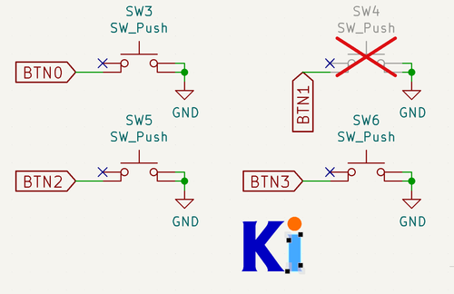
- A new set of utilities called 'Pin Helpers' has been introduced for quickly creating labels, guides, and indicators for disconnected connections.
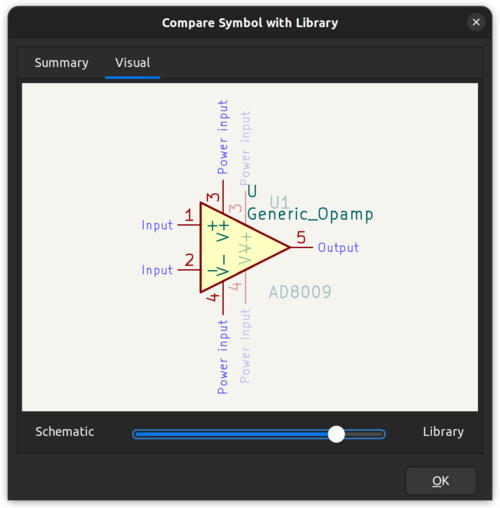
- An interface has been added for visually identifying symbols that differ across library versions.

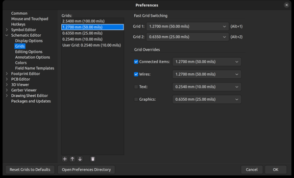
- The schematic editor now features extended grid settings and allows for overriding the grid view used during operations (moving, placing elements) with specific types of objects (for example, a 1.27-millimeter grid for components and guides, but switching to a different size when placing text).

- The schematic editor allows editing of power symbol names (e.g., VCC and GND) without renaming them in the symbol library.
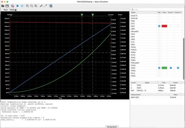
- The SPICE simulator has undergone a complete redesign of the user interface. The ability to create graphs with multiple signals has been added, along with analytical functions, cursor measurement capabilities, and support for displaying power on graphs in addition to voltage and current.

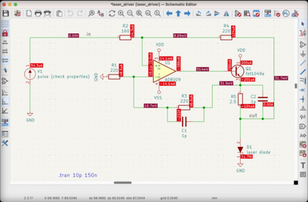
- Four new types of simulations have been implemented: pole-zero, noise, S-parameter, and FFT. Support for defining custom signals has been added, allowing expressions like 'V(/in) - V(/out)' to be displayed on graphs. There is now the possibility to show operating points on the schematic with simulation results.

- The PCB editor now offers the ability to move multiple footprints along with the traces attached to them at once.
- The tool for working with length tuning templates has been completely redesigned. Templates are now objects that can be selected, modified, and deleted after being placed on the board.
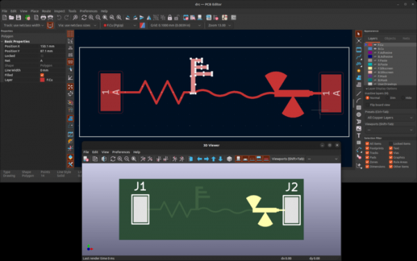
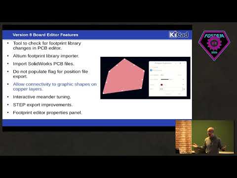
- In the PCB editor, the ability to bind graphic shapes, such as lines and rectangles, to a net has been added (previously, graphic shapes were rendered over the pad, separately from the electrically connected objects).

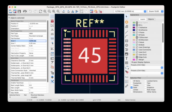
- The properties panel in the footprint editor has been enhanced to provide access to various properties of selected objects. The property value fields now support the use of mathematical expressions.

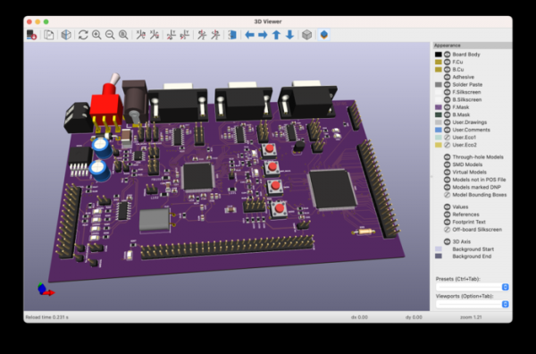
- The interface for viewing the 3D board layout has been redesigned. Visibility presets and the ability to save camera positions have been added.

Source: opennet.ru
