

After a year of development, the release of the open-source printed circuit board design system KiCad 9.0.0 has been published. This is the third significant release following the project's transition under the Linux Foundation. Builds are available for various Linux distributions, Windows, and macOS. The code is written in C++ using the wxWidgets library and is distributed under the GPLv3 license.
KiCad provides tools for editing electrical schematics and printed circuit boards, 3D visualization of boards, working with electrical circuit element libraries, manipulating Gerber-format templates, simulating electronic circuit operations, editing printed circuit boards, and project management. The project also provides libraries of electronic components, footprints, and 3D models. According to some printed circuit board manufacturers, about 15% of orders are received with schematics prepared in KiCad.
Among the changes in the new release:
- Support for 'Jobsets' has been added, allowing the creation of files with predefined operations on schematics and printed circuit boards that can be reused to replicate standard actions by different users. Jobsets can be executed both through the GUI and from the command line.
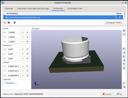
- Support for embedding various elements into schematics, routing, and footprints has been implemented instead of linking to external files. This change allows the creation of self-sufficient project files that do not depend on external files such as font and 3D model files.

- Support for the 'Bezier Curve' tool has been implemented in the schematic and PCB editors. Previously, Bezier-based connections could only be imported and edited, but now they can be created from scratch.
- Support for multi-channel design has been added, allowing the creation of new channels with similar placement and routing of components based on the existing layout of printed circuit boards.
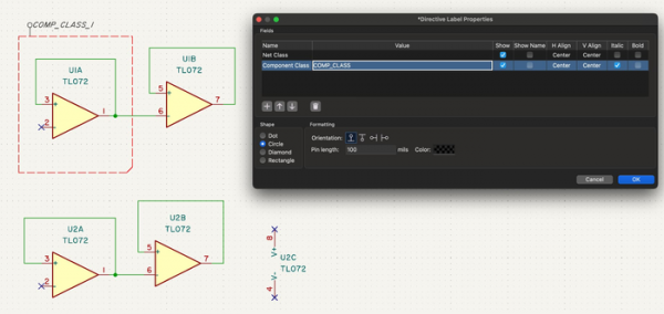
- Support for component classes has been added, allowing the grouping of various symbols and footprints into classes to which custom design rules can be applied.

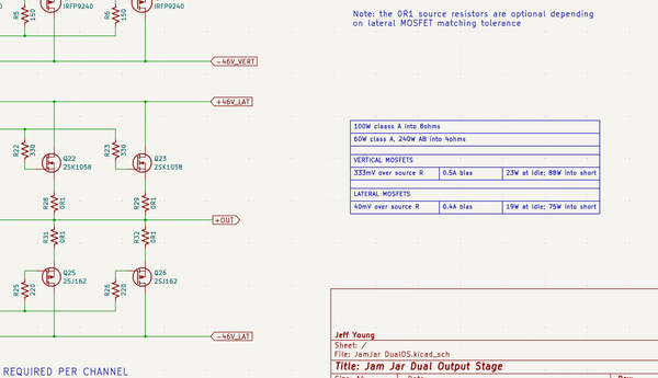
- Editing tables has been added to the editors for schematics, symbols, and footprints.

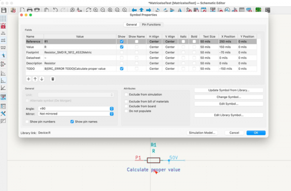
- The ability to define custom errors and warnings for ERC (Electrical Rules Check) and DRC (Design Rules Check) has been added.

- Support has been added for binding various actions to the mouse wheel in the editors for printed circuit boards, schematics, symbols, and footprints.
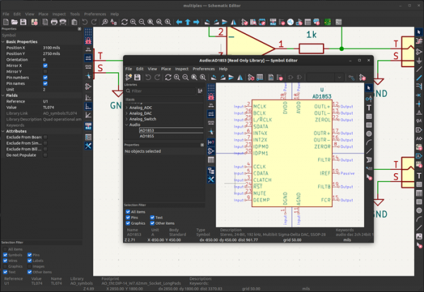
- Improvements in the schematic and symbol editors.
- The ability to highlight objects based on specified filters has been introduced.

- A tool for synchronizing sheet outputs and hierarchical labels has been added.
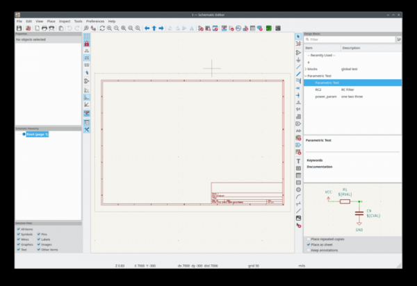
- Support for design blocks in schematics to create libraries of reusable circuit elements has been introduced.

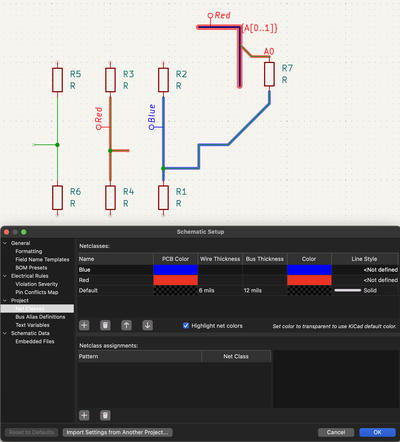
- A new class for highlighting connection traces by color has been added.

- The ability to highlight objects based on specified filters has been introduced.
- Improvements in the printed circuit board and footprint editors:
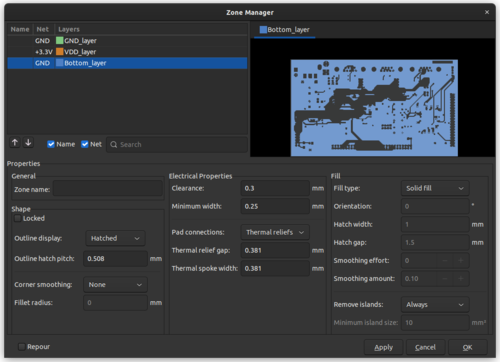
- A zone manager has been added, allowing users to view and configure zones without editing individual zones.

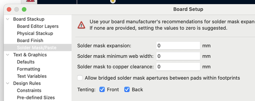
- You can now improve the tenting operations of the top and bottom layers.

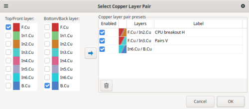
- Preset copper pair configurations have been added with the capability for quick switching between presets.

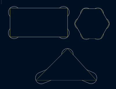
- A tool for changing shapes has been introduced.

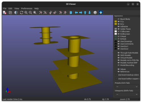
- The ability to create PTH pads with different shapes of copper pads across various layers has been added.

- Interactive positioning modes for objects and direct manipulation of objects have been added, enabling the movement of multiple traces at once.
- Support for exporting 3D models in XAO, STL, BREP, and PLY formats has been added.
- A zone manager has been added, allowing users to view and configure zones without editing individual zones.
Source: opennet.ru
