

After a year of development, the release of the open-source parametric 3D modeling system FreeCAD 1.1 has been published, featuring flexible customization options and increased functionality through plugin integration. The interface is built using the Qt library. Plugins can be created in Python. It supports saving and loading models in various formats, including STEP, IGES, and STL. The FreeCAD code is distributed under the LGPLv2 license, with Open CASCADE used as the modeling core. Ready-to-use builds are prepared for Linux (AppImage), macOS, and Windows.
FreeCAD allows users to explore different design options by changing model parameters and evaluating the work at various stages of the model's development. The project can serve as a free alternative to commercial CAD software such as CATIA, Solid Edge, and SolidWorks. Although FreeCAD is primarily aimed at mechanical engineering and product design development, the system can also be used in other fields, such as architectural design.
Among the changes:
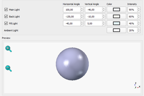
- The user interface has implemented support for three-point lighting to enhance the rendering quality of 3D models.

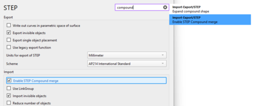
- A search panel has been added to the settings system.

- A new theme editor has been added, expanding options for modifying the style sheet.

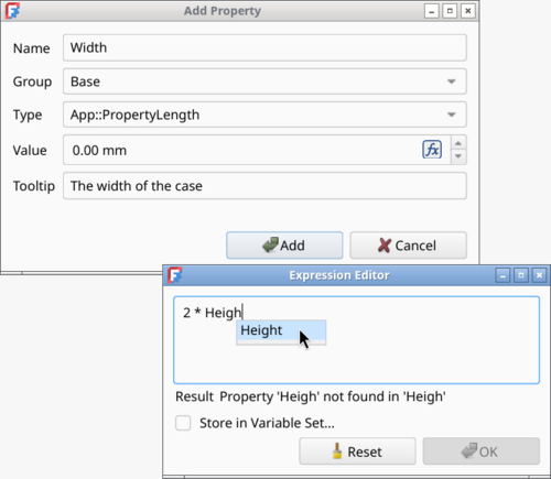
- The dialogue for adding properties has been enhanced, now supporting computed expressions, enumerations, and units of measurement. The property editor has improved tab autocompletion, variable set (VarSet) management, and window scaling.

- In the environment for creating parts (Part Design), options for using transparency and highlighting sketches during previews have been implemented to evaluate hidden surfaces and the structure of parts in volume. Interactive controls have been added to manipulate parameters in the 3D view window by dragging elements with the mouse. The task panel in the Hole Tool has been redesigned to hide irrelevant elements and show only those relevant to the current configuration.

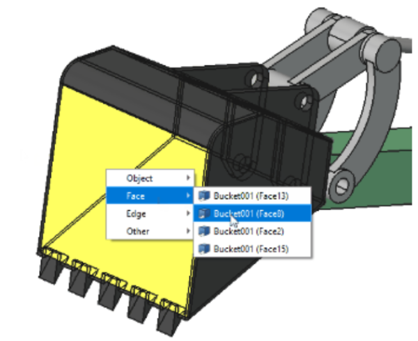
- The 'Clarify Selection' tool has been added, allowing for the refinement of selections of hidden or internal elements. The tool can be activated via a hotkey, through the context menu, or by holding down the left mouse button, after which the geometry of the model becomes transparent, and a menu for selecting overlapping objects is displayed.

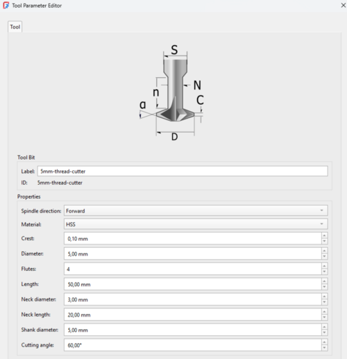
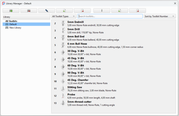
- In the CAM environment, used for creating machine instructions for CNC machines from 3D models, a new tool management system has been introduced. The CAM Tool Management component has been replaced with the Better Tool Library package, which was previously developed as an external plugin.

New interfaces for editing and selecting ToolBits have also been added to CAM, along with the capability to import from the G-Code simulator Camotics, command-line utilities for import and export, Drag & Drop functionality, clipboard support, a shape browser, and a built-in tool search feature. JSON format has been utilized for storing tool libraries.

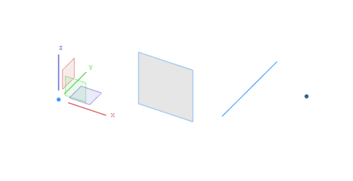
- Tools for creating reference elements (Core Datum) used in model design have been added, such as coordinate systems, reference points, auxiliary planes, and lines.

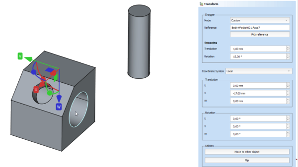
- The transformation tool (Transform) has been completely redesigned. It now allows the Dragger to align to the center of mass of the object, as well as to account for local (U, V, W) or global coordinate systems. A function for moving objects to a target position in the document has also been added.

- The capabilities of environments for designing assembly multi-component constructions (Assembly), modeling building objects (BIM, Building Information Modeling), 2D drawing (Draft), impact analysis (FEM, Finite Element Module), material handling (Material), part creation (Part), 2D shape sketching (Sketcher), and maintaining spreadsheets with model parameters (Spreadsheet) have been expanded, along with 2D modeling and the creation of 2D projections of 3D models (TechDraw).
- Performance has been improved on systems based on Wayland.

The release of the parametric 2D and 3D modeling system SolveSpace 3.2 has been published simultaneously. The system supports various methods for modeling 3D parts (such as extrusion, rotation, etc.), can simulate planar and spatial relationships, and utilize both planar and volumetric geometry when creating drawings. It can export models in 2D and volumetric formats like PDF, SVG, HPGL, STEP, DXF, and STL. The project code is written in C++ and is distributed under the GPLv3 license.
In SolveSpace 3.2, in addition to the GTK interface, an optional Qt6-based frontend for Linux has been introduced. An experimental version capable of operating through the Web, implemented using the Emscripten toolkit, has been added. The ability to apply constraints to edges is provided, and the range of objects to which constraints can be applied has been expanded. Behavior while working with sketches has been altered. Support for kerning in TrueType fonts has been added.
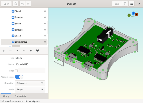
Additionally, the development of the parametric 3D design system Dune 3D, optimized for creating enclosures for electronic devices manufactured using 3D printing, is noteworthy. The system supports sketch creation and constraints in both two-dimensional and three-dimensional space, adding chamfers and fillets to edges of the 3D model, importing reference models in STEP format, and exporting in STEP, STL, and DXF formats. The project's code is written in C/C++ with a GTK interface and is distributed under the GPLv3 license.
Source: opennet.ru
