

On March 20, 2026, version 10.0.0 of the KiCAD printed circuit board design automation system was released.
Most, if not all, of the features and usability improvements in the new version are described in the discussion on the user forum. Some of them were also presented at presentation FOSDEM 2026. A more detailed and comprehensive list list of all changes is available on GitLab.
Application Area
KiCAD is a free printed circuit board design automation system. Currently, it is one of the most popular programs of its kind on Linux. Among free alternatives areHorizon-EDA LibrePCB and In numbers.
KiCAD 10 includes changes from hundreds of developers, translators, library contributors, and documentation compilers. A total of 7609 unique commits with code changes and translations have contributed to the new major version.
In the ninth version, a transition to the STEP format for 3D models included in libraries occurred. Starting with the tenth version, there has been a shift to using only STEP files (previously, WRML format was also used), which significantly reduces the space occupied by 3D models upon installation and provides better geometric accuracy with fewer discrepancies between visualization in KiCAD and the results of exporting it. User contributions to the project's libraries (schematic and others) included 952 new symbols, 1216 new footprints, and 386 new 3D models. In 2025, the library development team grew by 5 new members, assisting with both the tools and code review. After a comprehensive overhaul of the toolset, most footprints in the library are now generated—over 78% of footprints are now generated rather than drawn manually. Several generators have also been introduced to produce both a 3D model and a footprint from a single description. The median time to close a pull request decreased from 3 days to 18 hours, despite a larger number of pull requests than ever before (2105 new pull requests in 2025, compared to 2010 in 2024).
Other significant changes
New import capabilities from other CAD systems:
KiCAD 10 can import projects from Allegro, PADS, and gEDA / LeptonPCB. Customizable toolbars:
The ability to customize toolbars has been added. Support for undo and redo actions in dialog windows:
Support for undoing and redoing actions in dialog boxes: The ability to undo actions in dialog windows has been added before they are closed.
Lasso Selection: In both the schematic editor and the PCB editor, the ability to select objects using 'Lasso' has been added.
Dark Theme on Windows: Thanks to the collaboration between the KiCAD developers and the wxWidgets team, the graphical toolkit used by the project, KiCAD now supports dark theme functionality on Windows and will automatically follow the system's dark or light theme selection.
Schematic Editor
Options: The ability for design alternatives has been added: a way to track changes across different versions of one project that share a schematic but differ in properties (e.g., different component lists).
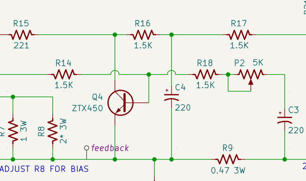
Hop-over Display: Another long-requested feature has been added: intersections of conductors on the schematic that are not connected to each other are now displayed as 'bridge' arcs rather than as straight lines without a point marking the intersection. (Illustration 2).
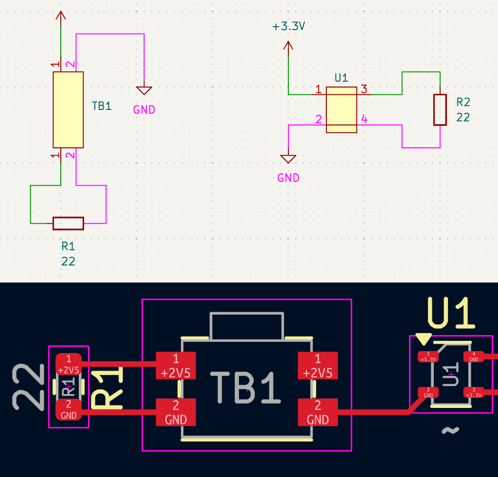
Support for Jumpers: The ability to use jumpers, sets of pinouts of a symbol and footprint that should be treated as connected internally has been added. Jumpers will always have a single net, allowing for the representation of components that have electrical connections outside the board.
Support for Grouping: Components can now be grouped not only in the PCB editor but also in the schematic editor.
CSV for Pinout Table: Support for exporting and importing pinout tables from CSV files has been added, providing greater flexibility for creating and editing complex components.
PCB Editor
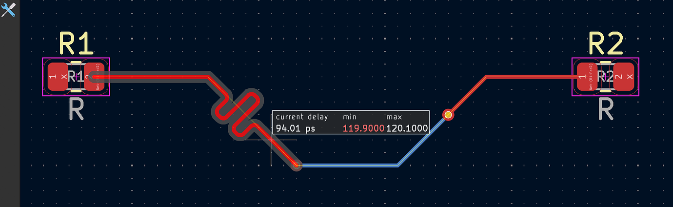
Time Domain Parameters: The track time domain settings system has been completely overhauled, including an update to the algorithm that increases compliance between the router and the design rule check (DRC) system. Support for setting constraints in the time domain has been added instead of just length constraints. Support for configuration profiles has been added, allowing for the specification of signal routing parameters on each layer of the PCB.
Blocks in the PCB Editor: The ability to combine parts of printed circuit board layouts into reusable blocks, introduced in version nine, has been expanded. Users can now create and manage libraries of printed circuit board layouts. Both the schematic editor and the layout editor have been enhanced with new convenient features.
Support for intra-layer objects in landing pads has been added. This means users can now include graphic shapes and cutouts on the inner layer, rather than being limited to just the front or back layers as in previous versions.
Pin and logical element replacement: The function for replacing pins/contact pads and logical elements/nodes has been implemented, allowing for direct and reverse annotation between the schematic and printed circuit board.
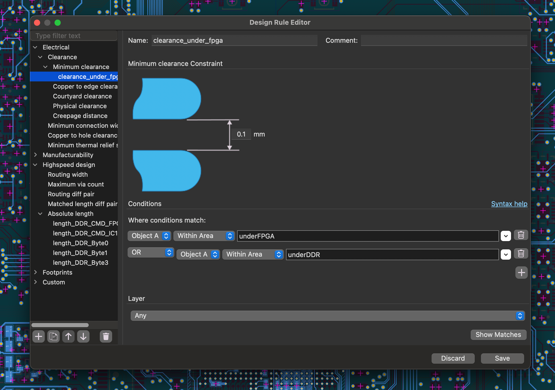
Graphic design rule editor: A new design rule editor dialog has been developed that allows for graphical creation of rules. Rules created with this tool are fully compatible with the existing rule specification language, enabling users to start with the graphical interface and advance to more complex rules as they become familiar with the software.
In addition to the above, many other useful features have been added, such as barcode support, patterned fill for graphic shapes, precise editing of polygon points, recommended actions for correcting design rule errors, export to 3D PDF, and much more!
Source: linux.org.ru
