


At the meeting 0x0A DC7831 On February 16, we presented a report on the basic principles of binary code emulation and our own development — a hardware platform emulator. .
In this article, we will describe how to launch a device's firmware in the emulator, demonstrate interaction with the debugger, and perform a small dynamic analysis of the firmware.
Background
A long time ago in a galaxy far far away
A couple of years ago, our lab needed to investigate the firmware of a device. The firmware was compressed and unpacked by the bootloader in a rather convoluted way, transferring data in memory multiple times. Moreover, the firmware actively interacted with peripherals. All of this was on a MIPS core.
The existing emulators did not meet our needs for objective reasons, but we still wanted to run the code. So, we decided to create our own emulator that would do the minimum and allow unpacking of the main firmware. We tried it, and it worked. We thought, what if we add peripherals to also execute the main firmware? It wasn't too painful — and it worked too. Again, we thought about creating a full-fledged emulator.
Ultimately, we created a computational systems emulator. .

Why Kopycat?
It's a play on words.
- copycat (English, noun [ˈkɒpɪkæt]) — imitator, mimic
- cat (English, noun [ˈkæt]) — cat — the favorite animal of one of the project's creators
- The letter 'K' comes from the Kotlin programming language
Kopycat
When creating the emulator, specific goals were set:
- the ability to quickly create new peripherals, modules, and processor cores;
- the ability to assemble a virtual device from various modules;
- the ability to load any binary data (firmware) into the virtual device's memory;
- the ability to work with snapshots (system state captures);
- the ability to interact with the emulator via a built-in debugger;
- a pleasant modern language for development.
As a result, Kotlin was chosen for implementation, a bus architecture (where modules connect through virtual data buses), JSON as the device description format, and GDB RSP as the protocol for interacting with the debugger.
Development has been ongoing for just over two years and is actively continuing. During this time, MIPS, x86, V850ES, ARM, and PowerPC processor cores have been implemented.
The project is growing, and it's time to introduce it to the wider public. A detailed project description will be provided later; for now, let’s focus on using Kopycat.
For the most impatient — the promo version of the emulator can be downloaded from .
Rhino in the emulator
Recall that a test device called 'Rhino' was created for the SMARTRHINO-2018 conference to train reverse engineering skills. The process of static firmware analysis was described in .
Now let’s try to add some ‘dynamics’ and run the firmware in the emulator.
We will need:
1) Java 1.8
2) Python and the module to use Python within the emulator. The WHL build of the Jep module for Windows can be .
For Windows:
1)
2)
For Linux:
1) socat
Eclipse, IDA Pro, or radare2 can be used as a GDB client.
Initially, a check is performed: does the client device support power via PoE? A voltage of 2.8 to 10 volts is supplied, and the input resistance is determined. If the results obtained are satisfactory for powering via PoE, the power device proceeds to the next stage.
To perform firmware in the emulator, it is necessary to 'build' a virtual device that represents an analogue of the real device.
The real device ('rhino') can be shown in a structural diagram:
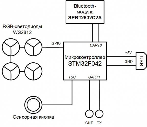
The emulator has a modular structure, and the final virtual device can be described in a JSON file.
JSON with 105 lines
{
  "top": true,

  // Plugin name should be the same as file name (or full path from library start)
  "plugin": "rhino",

  // Directory where plugin places
  "library": "user",

  // Plugin parameters (constructor parameters if jar-plugin version)
  "params": [
    { "name": "tty_dbg", "type": "String"},
    { "name": "tty_bt", "type": "String"},
    { "name": "firmware", "type": "String", "default": "NUL"}
  ],

  // Plugin outer ports
  "ports": [  ],

  // Plugin internal buses
  "buses": [
    { "name": "mem", "size": "BUS30" },
    { "name": "nand", "size": "4" },
    { "name": "gpio", "size": "BUS32" }
  ],

  // Plugin internal components
  "modules": [
    {
      "name": "u1_stm32",
      "plugin": "STM32F042",
      "library": "mcu",
      "params": {
        "firmware:String": "params.firmware"
      }
    },
    {
      "name": "usart_debug",
      "plugin": "UartSerialTerminal",
      "library": "terminals",
      "params": {
        "tty": "params.tty_dbg"
      }
    },
    {
      "name": "term_bt",
      "plugin": "UartSerialTerminal",
      "library": "terminals",
      "params": {
        "tty": "params.tty_bt"
      }
    },
    {
      "name": "bluetooth",
      "plugin": "BT",
      "library": "mcu"
    },

    { "name": "led_0",  "plugin": "LED", "library": "mcu" },
    { "name": "led_1",  "plugin": "LED", "library": "mcu" },
    { "name": "led_2",  "plugin": "LED", "library": "mcu" },
    { "name": "led_3",  "plugin": "LED", "library": "mcu" },
    { "name": "led_4",  "plugin": "LED", "library": "mcu" },
    { "name": "led_5",  "plugin": "LED", "library": "mcu" },
    { "name": "led_6",  "plugin": "LED", "library": "mcu" },
    { "name": "led_7",  "plugin": "LED", "library": "mcu" },
    { "name": "led_8",  "plugin": "LED", "library": "mcu" },
    { "name": "led_9",  "plugin": "LED", "library": "mcu" },
    { "name": "led_10", "plugin": "LED", "library": "mcu" },
    { "name": "led_11", "plugin": "LED", "library": "mcu" },
    { "name": "led_12", "plugin": "LED", "library": "mcu" },
    { "name": "led_13", "plugin": "LED", "library": "mcu" },
    { "name": "led_14", "plugin": "LED", "library": "mcu" },
    { "name": "led_15", "plugin": "LED", "library": "mcu" }
  ],

  // Plugin connection between components
  "connections": [
    [ "u1_stm32.ports.usart1_m", "usart_debug.ports.term_s"],
    [ "u1_stm32.ports.usart1_s", "usart_debug.ports.term_m"],

    [ "u1_stm32.ports.usart2_m", "bluetooth.ports.usart_m"],
    [ "u1_stm32.ports.usart2_s", "bluetooth.ports.usart_s"],

    [ "bluetooth.ports.bt_s", "term_bt.ports.term_m"],
    [ "bluetooth.ports.bt_m", "term_bt.ports.term_s"],

    [ "led_0.ports.pin",  "u1_stm32.buses.pin_output_a", "0x00"],
    [ "led_1.ports.pin",  "u1_stm32.buses.pin_output_a", "0x01"],
    [ "led_2.ports.pin",  "u1_stm32.buses.pin_output_a", "0x02"],
    [ "led_3.ports.pin",  "u1_stm32.buses.pin_output_a", "0x03"],
    [ "led_4.ports.pin",  "u1_stm32.buses.pin_output_a", "0x04"],
    [ "led_5.ports.pin",  "u1_stm32.buses.pin_output_a", "0x05"],
    [ "led_6.ports.pin",  "u1_stm32.buses.pin_output_a", "0x06"],
    [ "led_7.ports.pin",  "u1_stm32.buses.pin_output_a", "0x07"],
    [ "led_8.ports.pin",  "u1_stm32.buses.pin_output_a", "0x08"],
    [ "led_9.ports.pin",  "u1_stm32.buses.pin_output_a", "0x09"],
    [ "led_10.ports.pin", "u1_stm32.buses.pin_output_a", "0x0A"],
    [ "led_11.ports.pin", "u1_stm32.buses.pin_output_a", "0x0B"],
    [ "led_12.ports.pin", "u1_stm32.buses.pin_output_a", "0x0C"],
    [ "led_13.ports.pin", "u1_stm32.buses.pin_output_a", "0x0D"],
    [ "led_14.ports.pin", "u1_stm32.buses.pin_output_a", "0x0E"],
    [ "led_15.ports.pin", "u1_stm32.buses.pin_output_a", "0x0F"]
  ]
}
Please note the parameter firmware in the section params — this is the filename that can be uploaded to the virtual device as firmware.
The virtual device and its interaction with the host operating system can be represented by the following diagram:
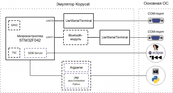
The current test instance of the emulator implies interaction with the COM ports of the main OS (debug UART and UART for the Bluetooth module). These can be real ports to which devices are connected or virtual COM ports (for which com0com / socat is needed). com0com / socat.
Currently, there are two main ways to interact with the emulator externally:
- the GDB RSP protocol (supported by tools such as Eclipse / IDA / radare2);
- the internal command line of the emulator (Argparse or Python).
Virtual COM ports
To interact with the UART of the virtual device on the local machine through a terminal, it is necessary to create a pair of linked virtual COM ports. In our case, one port is used by the emulator, and the second is used by the terminal program (PuTTY or screen):
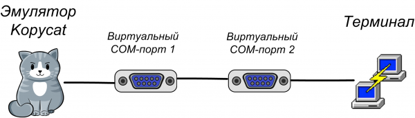
Using com0com
Virtual COM ports are configured using the setup utility from the com0com package (console version — C:Program Files (x86)com0comsetupc.exe, or GUI version — C:Program Files (x86)com0comsetupg.exe):
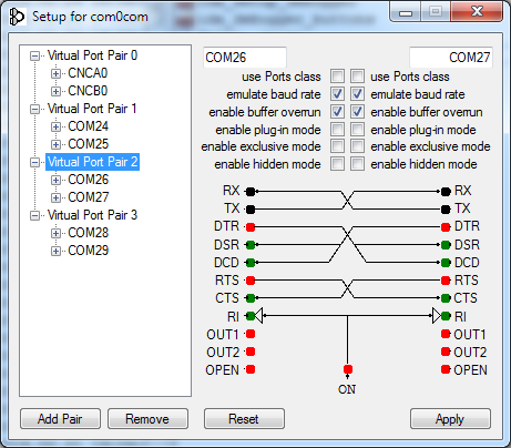
You should check the boxes enable buffer overrun for all created virtual ports; otherwise, the emulator will be waiting for a response from the COM port.
Using socat
On UNIX systems, virtual COM ports are automatically created by the emulator using the socat utility; it is sufficient to specify the prefix socat:.
Internal command line interface (Argparse or Python)
Since Kopycat is a console application, to interact with its objects and variables, the emulator provides two alternatives for the command line interface: Argparse and Python.
Argparse is the CLI built into Kopycat, it is always available to everyone.
An alternative CLI is the Python interpreter. To use it, you must install the Python module Jep and configure the emulator to work with Python (the Python interpreter installed on the user's main system will be used).
Installing the Python module Jep
On Linux, Jep can be installed via pip:
pip install jepTo install Jep on Windows, you need to first install the Windows SDK and the corresponding Microsoft Visual Studio. We have simplified your task a bit and created JEP for current versions of Python for Windows, so the module can be installed from the file:
pip install jep-3.8.2-cp27-cp27m-win_amd64.whlTo verify the installation of Jep, you need to run in the command line:
python -c "import jep"The response should be:
ImportError: Jep is not supported in standalone Python, it must be embedded in Java.In the command file of the emulator for your system (kopycat.bat — for Windows, kopycat — for Linux) add the parameter to the list of options DEFAULT_JVM_OPTS add the additional parameter Djava.library.path — it must contain the path to the installed Jep module.
As a result, for Windows, the following string should be obtained:
set DEFAULT_JVM_OPTS="-XX:MaxMetaspaceSize=256m" "-XX:+UseParallelGC" "-XX:SurvivorRatio=6" "-XX:-UseGCOverheadLimit" "-Djava.library.path=C:/Python27/Lib/site-packages/jep"Starting Kopycat
The emulator is a console JVM application. Launching is done through the operating system command script (sh/cmd).
The command to start under Windows:
binkopycat -g 23946 -n rhino -l user -y library -p firmware=firmwarerhino_pass.bin,tty_dbg=COM26,tty_bt=COM28The command to start under Linux using the socat utility:
./bin/kopycat -g 23946 -n rhino -l user -y library -p firmware=./firmware/rhino_pass.bin, tty_dbg=socat:./COM26,tty_bt=socat:./COM28-g 23646— TCP port that will be opened for access to the GDB server;-n rhino— name of the primary system module (device in assembly);-l user— name of the library to search for the main module;-y library— path to search for modules included in the device;firmwarerhino_pass.bin— path to the firmware file;- COM26 and COM28 are virtual COM ports.
As a result, a prompt will be displayed Python > (or Argparse >):
18:07:59 INFO [eFactoryBuilder.create ]: Module top successfully created as top
18:07:59 INFO [ Module.initializeAndRes]: Setup core to top.u1_stm32.cortexm0.arm for top
18:07:59 INFO [ Module.initializeAndRes]: Setup debugger to top.u1_stm32.dbg for top
18:07:59 WARN [ Module.initializeAndRes]: Tracer wasn't found in top...
18:07:59 INFO [ Module.initializeAndRes]: Initializing ports and buses...
18:07:59 WARN [ Module.initializePortsA]: ATTENTION: Some ports has warning use printModulesPortsWarnings to see it...
18:07:59 FINE [ ARMv6CPU.reset ]: Set entry point address to 08006A75
18:07:59 INFO [ Module.initializeAndRes]: Module top is successfully initialized and reset as a top cell!
18:07:59 INFO [ Kopycat.open ]: Starting virtualization of board top[rhino] with arm[ARMv6Core]
18:07:59 INFO [ GDBServer.debuggerModule ]: Set new debugger module top.u1_stm32.dbg for GDB_SERVER(port=23946,alive=true)
Python >
Interacting with IDA Pro
As the source file for analysis in IDA for easier testing, we use the firmware of the 'Rhino' as an (which contains the metadata).
You can also use the main firmware without metadata.
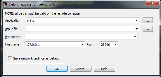
After launching Kopycat in IDA Pro, go to the Debugger menu and selectSwitch debugger…and choose 'Remote GDB Debugger«. Next, configure the connection: menu Debugger — Process options…
Set values:
- Application — any value
- Hostname: 127.0.0.1 (or the IP address of the remote machine where Kopycat is running)
- Port: 23946
The debug launch button (F9 key) is now available:

Press it — connection to the debugger module in the emulator occurs. IDA switches to debug mode, and additional windows become available: information about registers and the stack.
Now we can use all standard capabilities of the debugger:
- step-by-step execution of instructions (Step into and Step over — F7 and F8 keys, respectively);
- starting and pausing execution;
- setting breakpoints both on code and data (F2 key).
Connecting to the debugger does not mean launching the firmware code. The current position for execution should be the address 0x08006A74 — the start of the function Reset_Handler. If you scroll down the listing, you can see the function call. mainYou can place the cursor on this line (address 0x08006ABE) and perform the operation Run until cursor (F4 key).
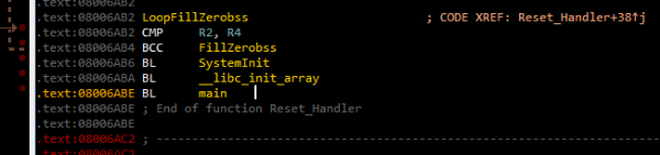
Then you can press F7 to enter the function main.
If you execute the command Continue process (F9 key), a "Please wait" window will appear with a single button Suspend:
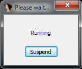
When pressed Suspend the execution of the firmware code is paused and can be resumed from the same address in the code where it was interrupted.
If you continue executing the code, you can see the following lines in the terminals connected to the virtual COM ports:
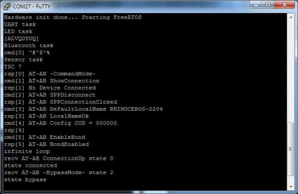
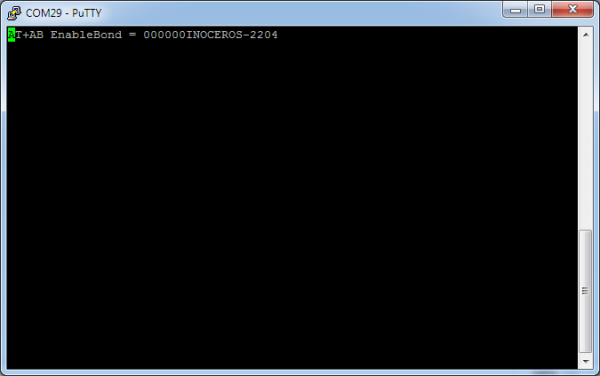
The presence of the line "state bypass" indicates that the virtual Bluetooth module has switched to receiving data from the user’s COM port.
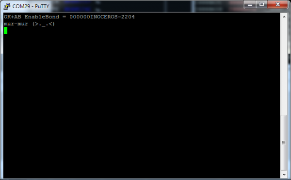
Now in the Bluetooth terminal (shown as COM29), you can enter commands according to the "Rhinoceros" protocol. For example, upon the command "MEOW", the Bluetooth terminal will return the string "mur-mur":
Don’t fully emulate me
When building the emulator, you can choose the level of detail/emulation of this or that device. For example, the Bluetooth module can be emulated in different ways:
- the entire device is emulated with a full set of commands;
- AT commands are emulated, while the data stream is received from the primary system's COM port;
- the virtual device provides complete redirection of data to the real device;
- as a simple stub that always returns "OK."
In the current version of the emulator, a second approach is used — a virtual Bluetooth module configures itself, after which it enters the "proxying" mode, transferring data from the main system's COM port to the emulator's UART port.

Let's consider the possibility of simple code instrumentation in case a certain piece of peripheral hardware is not implemented. For example, if a timer responsible for controlling data transmission in DMA is not created (the check is performed in the function ws2812b_wait, located at address 0x08006840), then the firmware will always wait for the flag reset busy, located at address 0x200004C4, which indicates the data line status of the DMA:
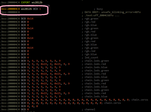
We can bypass this situation by manually resetting the flag busy immediately after it is set. In IDA Pro, you can create a Python function and call it at the breakpoint, while placing the breakpoint in the code after writing the value 1 to the flag. busy.
Breakpoint handler
First, let's create a Python function in IDA. The menu File — Script command…
Add a new snippet to the list on the left, give it a name (for example, BPT),
), in the text box on the right, input the function code:
def skip_dma():
    print "Skipping wait ws2812..."
    value = Byte(0x200004C4)
    if value == 1:
        PatchDbgByte(0x200004C4, 0)
return False 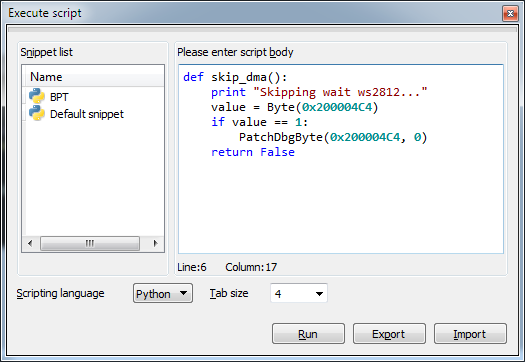
After that, click Run and close the script window.
Now let's go to the code at address 0x0800688A, set a breakpoint (key F2), edit it (context menu Edit breakpoint…), and do not forget to set the script type to Python:
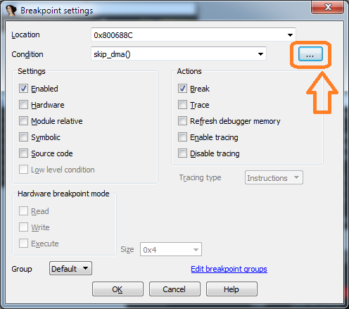
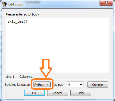
If the current value of the flag busy is equal to 1, then the function skip_dma should be executed in the script line:
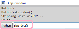
If you run the firmware, the breakpoint handler code can be seen in IDA in the window Output with the line Skipping wait ws2812.... Now the firmware will not wait for the flag reset. busy.
Interaction with the emulator
Emulation for the sake of emulation is unlikely to bring joy and excitement. It is much more interesting if the emulator helps the researcher see data in memory or establish interaction between threads.
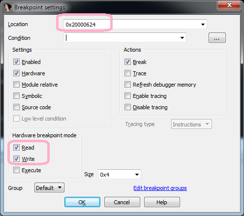
Let's demonstrate how to establish RTOS task interaction dynamically. Before that, the code execution should be paused if it is running. If we go to the function bluetooth_task_entry in the command handling branch for "LED" (address 0x080057B8), we can see that a message is first created and then sent to the system queue ledControlQueueHandle. A breakpoint should be set on the variable access
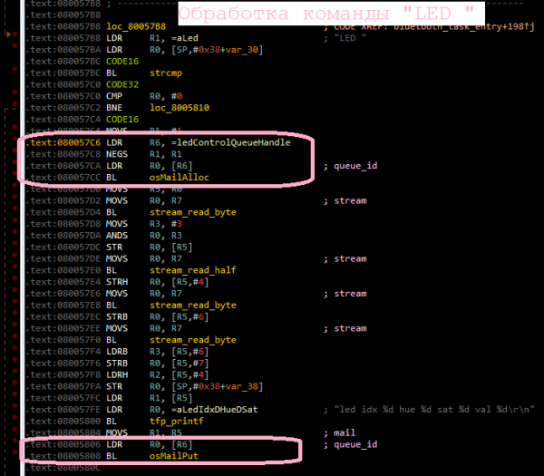
and the code execution should be continued: ledControlQueueHandle., located at address 0x20000624 and continue executing the code:
As a result, it will first stop at the address 0x080057CA before the function call osMailAlloc, then at the address 0x08005806 before the function call osMailPut, after some time it will stop at the address 0x08005BD4 (before the function call osMailGet), which belongs to the function leds_task_entry (LED task), meaning that there was a task switch and control has now passed to the LED task.
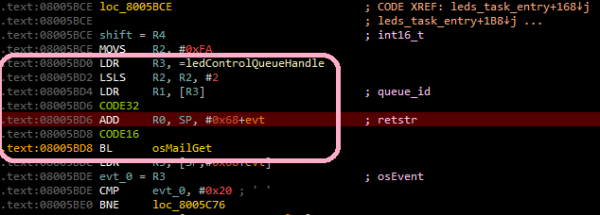
This simple method allows us to establish how RTOS tasks interact with each other.
Of course, in practice, task interactions can be more complex, but using an emulator makes tracking this interaction less labor-intensive.
You can watch a short video on running the emulator and interacting with IDA Pro.
Running with Radare2
We cannot overlook such a versatile tool as Radare2.
To connect to the emulator using r2 the command will look like this:
radare2 -A -a arm -b 16 -d gdb://localhost:23946 rhino_fw42k6.elfCurrently, both starting (dc) and pausing execution (Ctrl+C) are available.
Unfortunately, at this moment, r2 has issues when working with a hardware GDB server and memory mapping, which is why breakpoints and Steps (the command ds) are not functioning. We hope this will be fixed soon.
Running with Eclipse
One of the options for using the emulator is debugging the firmware of the device being developed. For clarity, we will also use the firmware "Rhinoceros." You can download the firmware sources .
We will use Eclipse from the suite .
To load the firmware directly built in Eclipse into the emulator, you need to add the parameter firmware=null to the emulator launch command:
binkopycat -g 23946 -n rhino -l user -y modules -p firmware=null,tty_dbg=COM26,tty_bt=COM28Setting up the debug configuration
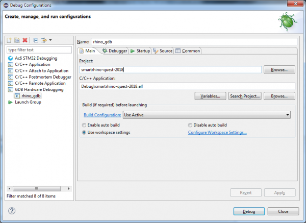
In Eclipse, select the menu Run — Debug Configurations… In the opened window, in the section GDB Hardware Debugging you need to add a new configuration, after which on the "Main" tab specify the current project and the application to debug:
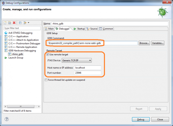
On the "Debugger" tab, you need to specify the GDB command:
${openstm32_compiler_path}arm-none-eabi-gdb
You also need to enter parameters to connect to the GDB server (host and port):
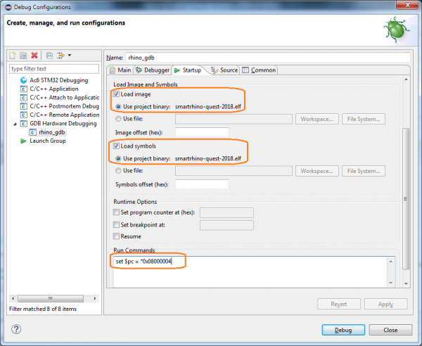
On the "Startup" tab, you need to specify the following parameters:
- check the box Load image (to load the built firmware image into the emulator);
- check the box Load symbols;
- add the launch command:
set $pc = *0x08000004(register the PC value from memory at the address0x08000004— it stores the address ResetHandler).
Note that, if you don't want to load the firmware file from Eclipse, then the parameters Load image and Run commands do not need to be specified.
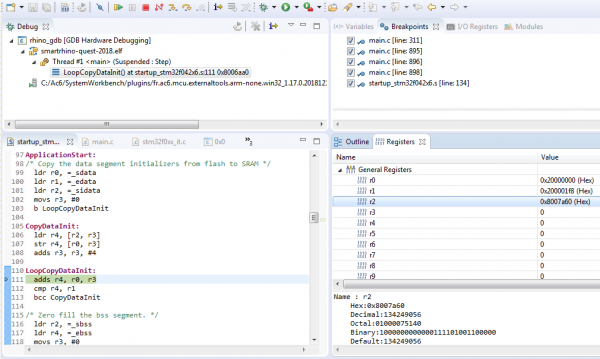
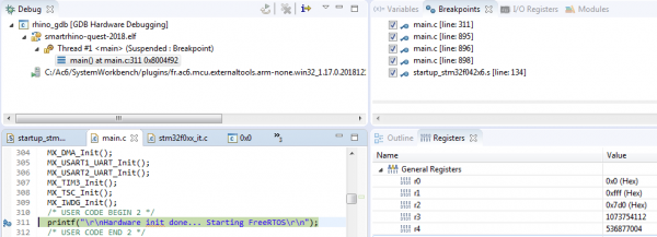
After clicking Debug, you can work in debugger mode:
- step-by-step execution of code

- interacting with breakpoints

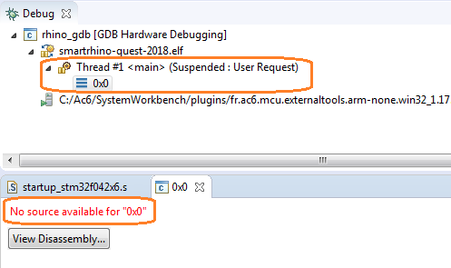
Note. Eclipse has, hmm... some quirks... and you have to live with them. For example, if a message ‘No source available for
In conclusion
Emulating native code is quite an interesting task. For device developers, it provides the opportunity to debug firmware without actual hardware. For researchers, it allows for dynamic code analysis, which is not always possible even when having the device.
We want to provide specialists with a tool that is convenient, relatively simple, and does not take much effort and time to set up and launch.
Share your experience with hardware emulators in the comments. We invite discussion and will be happy to answer questions.
Only registered users can participate in the survey. , please.
What do you use the emulator for?
developing (debugging) firmware
researching firmware
running games (Dendi, Sega, PSP)
something else (let us know in the comments)
7 users voted. 2 users abstained.
What software do you use for native code emulation?
QEMU
Unicorn engine
Proteus
something else (let us know in the comments)
6 users voted. 2 users abstained.
What would you like to improve in the emulator you are using?
I want speed
I want ease of setup/launch
I want more interaction capabilities with the emulator (API, hooks)
I'm satisfied with everything
something else (let us know in the comments)
8 users voted. 1 user abstained.
Source: habr.com
