

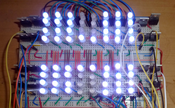
Microelectronics have become a trendy hobby in recent years thanks to the wonderful Arduino. However, there's a catch: with sufficient interest, one can quickly outgrow DigitalWrite(), but what to do next is not entirely clear. The Arduino developers have made considerable efforts to lower the entry barrier to their ecosystem, yet beyond it lies the dark forest of harsh circuit design, which remains elusive to enthusiasts.
For instance, datasheets. They seem to contain everything you need, just take and use them. But their authors clearly do not aim to popularize microcontrollers; sometimes it seems, they deliberately abuse obscure terms and abbreviations when describing simple things to confuse the uninitiated as much as possible. But not everything is so grim; with some effort, the mystery can be unraveled.
In this article, I will share my experiences as a humanities major dealing with datasheets for hobby purposes. The text is intended for those who have moved beyond the basics of Arduino and expect some understanding of how microcontrollers work.
Let's start with a traditional
Blinking an LED on Arduino
And here's the code:
void setup() {
DDRB |= (1<<5);
}

void loop() {
PINB = (1<<5);
for (volatile uint32_t k=0; k<100000; k++);
}
"What is this?" – asks the seasoned reader. "Why are you writing something to the input register PINB? It's read-only!" Indeed, , like many educational articles on the internet, asserts that this register is read-only. I thought so too until I reread the Atmega328p when preparing this article. And it says:

This is a relatively new feature; it wasn't available in Atmega8, and not everyone knows about it or mentions it due to backward compatibility concerns. However, it is quite useful for demonstrating that datasheets should be read to utilize all the chip's capabilities, including the lesser-known ones. And this isn't the only reason.
Why else read datasheets
Usually, Arduino enthusiasts, after playing with LEDs and AnalogWrites, start connecting various modules and chips to the board, for which libraries have already been written. Eventually, a library appears that doesn't work as expected. Then the enthusiast begins to tinker with it to fix it, and there...
Something incomprehensible is happening there, which is why I have to go to Google, read numerous tutorials, snag pieces of someone else's suitable code, and finally achieve my goal. This gives a powerful sense of accomplishment, but in reality, the process resembles inventing a bike by reverse-engineering a motorcycle. Moreover, I’m not gaining any understanding of how this bike works. I know this because I’ve been at it for quite a while.
If instead of this fascinating activity, I had spent a couple of days studying the documentation for the Atmega328, I would have saved a huge amount of time. After all, it’s a pretty simple microcontroller.
Thus, reading datasheets is necessary just to have an idea of how the microcontroller is structured and what it can do. And also:
to check and optimize other people's libraries. They are often written by fellow enthusiasts reinventing the wheel; or, on the contrary, the authors deliberately add excessive safeguards against mistakes. Better to have three times more code that’s slower rather than it failing to work;
to enable the use of chips in my project for which no library has been written;
to ease the task of migrating from one line of microcontrollers to another;
to finally optimize my old code that wouldn’t fit into Arduino;
to learn to control any chip directly through its registers, without worrying about figuring out the details of its libraries, if they even exist.
Why write to registers directly when there are HAL and LL?
Glossary
HAL, High Abstraction Layer – a library for controlling a microcontroller with a high level of abstraction. If you need to use the SPI1 interface, just configure and enable SPI1 without worrying about which registers are responsible for what.
LL, Low Level API – a library containing macros or structures with register addresses, allowing access to them by name. DDRx, PORTx, PINx on the Atmega are part of LL.
Discussions around 'HAL, LL, or registers' regularly occur in the comments on Habr. Without claiming access to astral knowledge, I’d simply like to share my amateur experience and thoughts.
Having somewhat figured out Atmega and read articles about the wonders of STM32, I bought half a dozen different boards – both Discovery and the 'Blue Pills', and even just chips for my own projects. They all collected dust in a box for two years. Occasionally, I'd tell myself: 'That's it, I'll master STM this weekend', launch CubeMX, generate a setup for SPI, look at the resulting wall of text, generously sprinkled with STM copyrights, and decide that it was just too much.
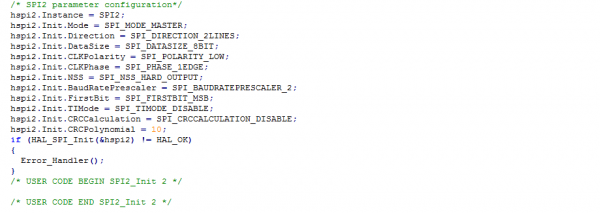
Of course, it is possible to figure out what CubeMX has written here. But at the same time, it's clear that memorizing all the formulations to write them down manually later is unrealistic. And debugging this, if I accidentally forget to check a box in Cube, is a completely different story.
Two years passed, and I still longed for all sorts of tasty chips that were beyond my understanding, and I stumbled upon one, albeit about STM8. And suddenly I realized that all this time I had been knocking on an open door: the registers in STM are arranged just like any other microcontroller, and Cube is not necessary to work with them. Wait, it could be done like that?
HAL and specifically STM32CubeMX is a tool for professional engineers who work closely with STM32 chips. The main feature is a high level of abstraction, the ability to quickly migrate from one microcontroller to another, and even from one core to another, while remaining within the STM32 family. Hobbyists encounter such tasks rarely – our choice of microcontrollers is typically limited to what’s available on AliExpress, and we more often migrate between radically different chips – moving from Atmega to STM, from STM to ESP, or whatever new goodies our Chinese friends throw our way. HAL won't help here, and studying it takes quite a bit of time.
That leaves LL – but it’s just a step away from registers. Personally, I find writing my own macros with register addresses to be useful: I study the datasheet more closely, think about what I will need in the future and what I certainly won’t, better structure my programs, and overall, overcoming this helps with memorization.
Moreover, there is a nuance with the popular STM32F103 – there are two incompatible versions of LL for it, one official from STM, the other from Leaf Labs, used in the STM32duino project. If writing an open-source library (and that was exactly ), I need to either create two versions or access the registers directly.
Finally, the refusal of LL, in my opinion, simplifies migration, especially if you plan for it from the very beginning of the project. An exaggerated example: let's write an Arduino blink in Atmel Studio without LL:
#include <stdint.h>

#define _REG(addr) (*(volatile uint8_t*)(addr))

#define DDR_B 0x24
#define OUT_B 0x25

int main(void)
{
    volatile uint32_t k;

    _REG(DDR_B) |= (1<<5);

    while(1)
    {
        _REG(OUT_B) |= (1<<5);
        for (k=0; k<50000; k++);
        _REG(OUT_B) &= ~(1<<5);
        for (k=0; k<50000; k++);
    }
}
To make this code blink an LED on a Chinese board with STM8 (from ST Visual Desktop), you only need to change two addresses:
#define DDR_B 0x5007
#define OUT_B 0x5005
Yes, I am using a specific feature of connecting the LED on this board; it will blink very slowly, but it will blink!
What types of datasheets are there
In articles and on forums, both in Russian and English, 'datasheets' refer to any technical documentation for chips, and I do the same in this text. Formally, they are just one type of such documentation:
Datasheet – technical specifications. It is mandatory for any electronic component. Reference information, useful to keep on hand, but there is not much to read thoughtfully. However, simpler chips are often limited to the datasheet to avoid creating unnecessary documents; in this case, Reference Manual it is included here as well.
Reference Manual – the actual manual, a hefty book of 1000+ pages. It details the operation of everything packed into the chip. The main document for mastering the microcontroller. Unlike datasheet, manuals are written for a broad range of MCUs, containing a lot of information about peripherals that may be absent in your specific model.
Programming Manual or Instruction Set Manual – the instruction for unique commands of the microcontroller. Intended for those who program in Assembly. Compiler authors actively use it for code optimization, so generally, we may not need it. But it's useful to glance here for general understanding, especially for some specific commands like interrupt exit, as well as when actively using a debugger.
Application Note – useful tips for solving specific tasks, often with code examples.
Errata Sheet – describes cases of unusual behavior of the chip with workarounds if available.
What can be found in datasheets
Directly in Datasheet we may need sections such as:
Device Summary – the first page of the datasheet briefly describes the device. Very useful in situations where you found a chip somewhere (saw it in a store, desoldered it, encountered a mention) and want to understand what it is.
General Description – a more detailed description of the chip's capabilities.
Pinouts – pinout diagrams for all possible chip packages (which pin corresponds to which leg).
Pin Description – a description of the purpose and capabilities of each pin.
Memory Map – a memory address map is unlikely to be needed, but it sometimes includes a table of register block addresses.
Register Map – the table of register block addresses is typically found in the datasheet, and in Ref Manual – only offsets (address offsets).
Electrical Characteristics – in this section, we are primarily interested in absolute maximum ratings, listing the maximum loads on the chip. Unlike the indestructible Atmega328p, most MCUs do not allow connecting serious loads to the pins, which can be an unpleasant surprise for Arduino enthusiasts.
Package Information – drawings of available packages, useful for designing your own boards.
Reference Manual structurally consists of sections dedicated to specific peripherals indicated in their titles. Each chapter can be conditionally divided into three parts:
Overview, Introduction, Features – an overview of the peripheral capabilities;
Functional Description, Usage Guide or simply the main block of the section – a detailed textual description of the principles of the peripheral's operation and methods of its use;
Registers – a description of control registers. In simple cases like GPIO or SPI, this might be sufficient to start using the peripheral, but often you still have to read the previous sections.
How to Read Datasheets
Datasheets can be intimidating at first due to their volume and the abundance of unfamiliar words. In reality, it's not that scary if you know a few hacks.
Install a good PDF reader. Datasheets are written in the proud traditions of paper manuals, and it's great to print them out, use plastic bookmarks, and bind them. Hypertext is present in minimal quantities. Fortunately, at least the document structure is organized with bookmarks, so a decent reader with easy navigation is really needed.
A datasheet is not a textbook by Stroustrup; it doesn't require reading everything in order. If you followed the previous advice – just find the necessary section in the bookmarks panel.
Datasheets, especially Reference Manuals, may describe the capabilities of not just a specific chip, but the entire series. This means that half, if not two-thirds of the information is not relevant to your chip. Before studying the TIM7 registers, check in General Description, do you have it?
Know English at least on a basic level. Datasheets are half composed of terms unfamiliar to the average speaker, and half made up of simple connecting constructs. Sometimes, there are wonderful Chinese datasheets in Chinglish, where half are also terms, and the other half is a random assortment of words.
If you encounter an unfamiliar word, don't try to translate it with an English-Russian dictionary. If you're puzzled by hysteresis, translating it as "hysteresis" won't make you feel warmer. Use Google, Stack Overflow, Wikipedia, forums where the relevant concept will be .
The best way to understand what you've read is to verify it in action. So keep a development board on hand that you're getting acquainted with, or preferably two – in case something is still unclear and you see that magical smoke.
It's a good habit to keep a datasheet handy when you're reading someone's tutorial or studying someone else's library. You might find a more optimal solution to your problem in it. Conversely, if the datasheet doesn’t help you understand how the register works, Google it: chances are, someone has already described everything in simple terms or left understandable code on GitHub.
Glossary
A few useful words and symbols to help you get to grips with datasheets more quickly. This is what I recalled over the past couple of days; additions and corrections are welcome.
Electricity
Vcc, Vdd – "plus", power
Vss, Vee – "minus", ground
current – current
voltage – voltage
to sink current – to act as a "ground" for external loads
to source current – to power external loads
high sink/source pin – pin with high "tolerance" to load
IO
H, High – on the Vcc pin
L, Low – on the Vss pin
High Impedance, Hi-Z, floating – nothing on the pin, "high impedance"; it is effectively invisible to the outside world.
weak pull up, weak pull down – built-in pull-up/pull-down resistor, roughly equivalent to 50 kΩ (see the datasheet). Used, for example, to ensure that the input pin doesn't float in the air, causing false triggers. Weak – because it can be easily "overridden."
push pull – output mode of the pin, in which it switches between High and Low – regular OUTPUT with Arduino.
open drain – designation of an output mode where the pin can be either Low, or High Impedance / FloatingHowever, this is almost never a "true" open drain; there are protective diodes, resistors, and so on. It is merely a designation for the ground/nothing mode.
true open drain – and here is a true open drain: the pin goes directly to ground when open, or stays in a suspended state when closed. This means that it can handle a voltage higher than Vcc if necessary, but the maximum is still specified in the datasheet in the section Absolute Maximum Ratings / Voltage.
Interfaces
in series – connected in series
to chain – connecting chips in a chain in series, increasing the number of outputs.
shift – shift, usually denotes bit shifting. Accordingly, to shift in and to shift out – to receive and transmit data bit by bit.
latch – latch, covering the buffer while bits are being shifted through it. When the transmission is completed, the latch opens, and the bits start to work.
to clock in – to perform bit-wise transmission, shifting all bits to their required positions.
double buffer, shadow register, preload register – denotes the history when a register must be able to accept new data but hold it until a certain point. For example, for proper PWM operation, its parameters (duty cycle, frequency) should not change until the current cycle is finished, but new parameters can already be transmitted. Accordingly, the current ones are held in shadow register, while the new ones go into preload register, being written into the corresponding chip register.
Any
prescaler – frequency divider
to set a bit – to set the bit to 1
to clear/reset a bit – to reset the bit to 0 (reset – a feature of STM datasheets)
What's Next
In general, a practical section was planned with demonstrations of three projects on STM32 and STM8, specifically made for this article using datasheets, with bulbs, SPI, timers, PWM, and interrupts:
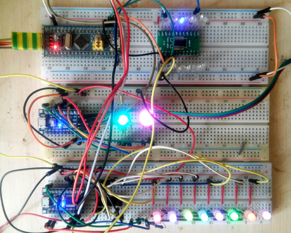
But there is quite a bit of text, so the projects will be moved to the second part.
The skill of reading datasheets will help you with your hobby, but it hardly replaces live communication with fellow enthusiasts in forums and chats. For this, you still need to improve your English first. Therefore, for those who have read to the end – a special reward: two free lessons at Skyeng with the first payment using the code HABR2.
Source: habr.com
