


Hello Habr!
Articles often use colorful images instead of electrical diagrams, leading to debates in the comments.
In light of this, I decided to write a brief article about the types of electrical diagrams classified in the Unified System for Design Documentation (ESKD).
Throughout the article, I will rely on the ESKD.
Consider .
This GOST introduces the concepts of:
- diagram type — a classification grouping of diagrams based on operational principles, product composition, and the interactions between its components;
- diagram type — a classification grouping based on their main purpose.
Let’s agree that we will have a single type of diagram — electrical diagram (E).
Let's analyze the types of diagrams described in this GOST.
| Diagram Type | Definition | Type Code |
|---|---|---|
| Structural Diagram | A document defining the main functional parts of the product, their purpose, and interconnections | 1 |
| Functional Diagram | A document explaining the processes occurring in individual functional circuits of the product (installation) or the product (installation) as a whole | 2 |
| Schematic Diagram (Complete) | A document defining the complete composition of elements and their interconnections, usually providing a full (detailed) understanding of the operational principles of the product (installation) | 3 |
| Wiring Diagram (Installation) | A document showing the connections of the product (installation) components and specifying wires, bundles, cables, or pipelines used for these connections, as well as their connection and entry points (connectors, boards, terminals, etc.) | 4 |
| Connection Diagram | A document showing the external connections of the product | 5 |
| General Diagram | A document defining the components of the complex and how they connect on site | 6 |
| Layout Diagram | A document defining the relative arrangement of the product (installation) components, and if necessary, also of bundles (wires, cables), pipelines, light guides, etc. | 7 |
| Combined Diagram | A document containing elements of various types of diagrams of one kind | 0 |
| Note — The names of the types of diagrams specified in parentheses set the standards for electrical diagrams of energy facilities. | ||
Next, we will examine each type of diagram in more detail concerning electrical diagrams.
Main document: .
So, what are these electrical diagrams and how are they used?
GOST 2.702-2011 will provide us with the answer: Electrical Diagram — a document that contains conditional images or designations of the parts of a product that operate using electrical energy and their interconnections..
Depending on their main purpose, electrical diagrams are divided into the following types:
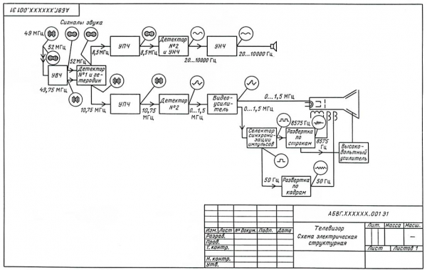
Structural electrical diagram (E1)
The structural diagram illustrates all the main functional parts of the product (elements, devices, and functional groups) and the primary interconnections between them. The graphical representation of the diagram should ensure the best understanding of the sequence of interactions of the functional parts within the product. It is recommended to indicate the direction of processes occurring in the product with arrows on the lines of interconnections.
Example of a structural electrical diagram:
Functional electrical diagram (E2)
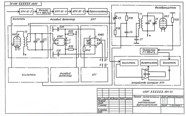
The functional diagram illustrates the functional parts of the product (elements, devices, and functional groups) involved in the process represented by the diagram, and the connections between these parts. The graphical representation of the diagram should provide the clearest view of the sequence of processes illustrated by the diagram.
Example of a functional electrical diagram:
Schematic electrical diagram (full) (E3)
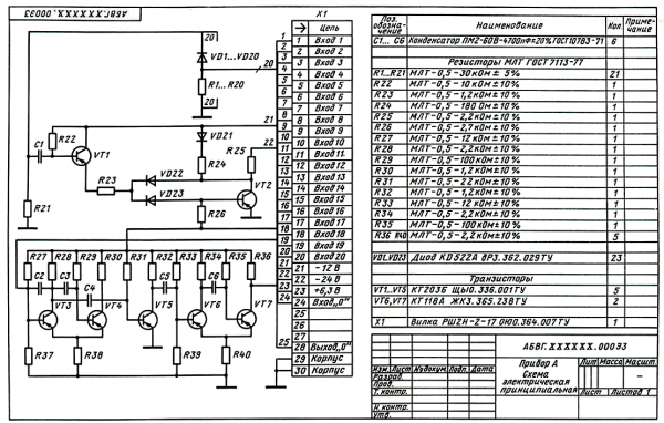
The schematic diagram displays all electrical elements or devices necessary for executing and controlling the established electrical processes within the product, all electrical interconnections between them, as well as electrical elements (connectors, terminals, etc.) that terminate the input and output circuits. The diagram may include connecting and mounting elements installed in the product for structural reasons. Diagrams are created for products in a powered-off state.
Example of an electrical circuit diagram:
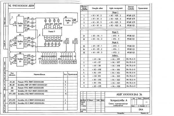
Electrical connection diagram (installation) (E4)
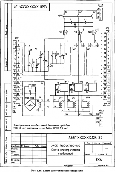
The connection diagram should illustrate all devices and elements included in the product, their input and output elements (connectors, boards, terminals, etc.), as well as the connections between these devices and elements. The placement of graphical representations of devices and elements on the diagram should roughly correspond to the actual layout of elements and devices in the product. The positions of input and output elements or terminals within the graphical representations and devices or elements should approximately match their actual locations in the device or element.
Example of an electrical connection diagram:
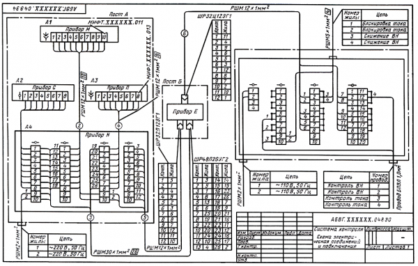
Electrical connection diagram (E5)
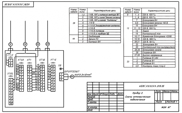
The connection diagram should depict the product, its input and output elements (connectors, terminals, etc.), and the ends of the wires and cables (multistrand wires, electrical cords) of external installation connected to them, alongside which information about the connection of the product should be placed (characteristics of external circuits and/or addresses). The positioning of input and output elements within the graphical representation of the product should approximately reflect their actual positions in the product. The diagram should specify positional designations for input and output elements assigned to them in the product's circuit diagram.
Example of an electrical connections diagram:
General electrical diagram (E6)
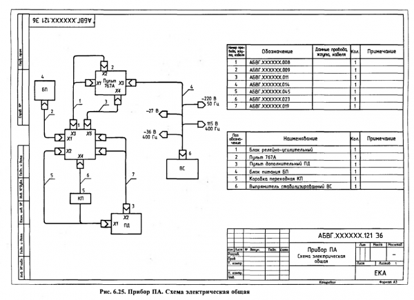
The general diagram illustrates the devices and elements included in the complex, as well as the wires, harnesses, and cables (multistrand wires, electrical cords) connecting these devices and elements. The placement of graphical representations of devices and elements on the diagram should roughly correspond to the actual layout of elements and devices in the product.
Example of a general electrical diagram:
Electrical layout diagram (E7)
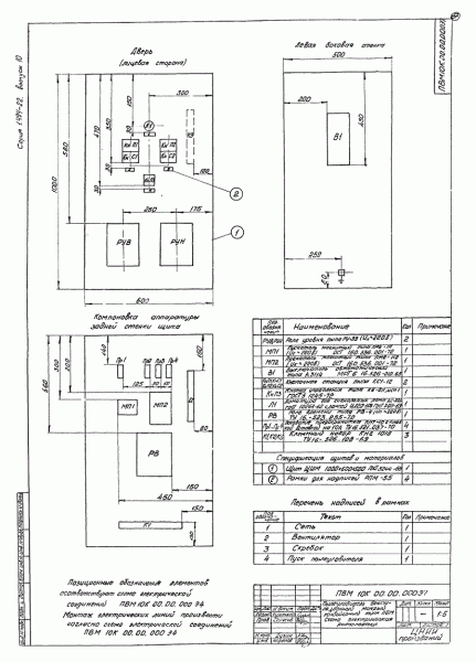
The layout diagram depicts the components of the product, and if necessary, the connections between them — the structure, room, or area where these components will be located.
Example of an electrical layout diagram:
Combined electrical diagram (E0)
This type of diagram shows various types that are interconnected on a single drawing.
Example of a combined electrical diagram:
PSThis is my first article on Habr, please be gentle.
Source: habr.com
