


This article discusses high-frequency radio signal amplifiers for cable television on the coaxial part of the trunk.
Contents of the article series
- Part 6: RF-signal amplifiers
- Part 7: Optical receivers
- Part 8: Optical backbone network
- Part 9: Headend
- Part 10: Troubleshooting in the CATV network
In cases where there is only one optical receiver in a house (or even an entire block) and all wiring to the risers is done with coaxial cable, signal amplification is essential at their start. In our network, we mainly use devices from Teleste, so I will explain based on their examples, but fundamentally the equipment from other manufacturers is not different, and the set of features for configuration is usually similar.
The model CXE180M has the minimum number of settings:
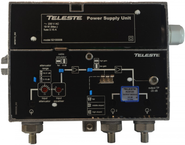
As you probably remember from previous parts, the signal has two important quantitative parameters: level and tilt. These are the ones that amplifier settings can help to correct. Let's start in order: immediately after the input connector is located the attenuator. It allows reducing the input signal by up to 31 dB (when switching the blue jumper according to the diagram, the range of the knob changes from 0-15 to 16-31 dB). This is necessary if the signal coming to the amplifier exceeds 70 dBμV. The reason is that the amplification stage raises the signal level by 40 dB, and we should not output more than 110 dBμV (above this level, the signal-to-noise ratio sharply decreases, and this figure is relevant for all broadband amplifiers and receivers with a built-in amplifier). Thus, if 80 dBμV enters the amplifier, for example, it will give us 120 dBμV of noise and distorted figures at the output. To avoid this, the input attenuator needs to be set to a 10 dB attenuation position.
After the attenuator, we see the equalizer. It is necessary to eliminate reverse tilt if it exists. This is achieved by reducing the signal level in the low-frequency range by up to 20 dB. It is worth noting that we cannot eliminate reverse tilt by raising the level of high frequencies; we can only suppress the lows.
These two tools are often sufficient to correct minor deviations in the signal from the norm. If this is not the case, the following can be used:
Cable simulator, designed as an insert that can be placed horizontally or vertically, simulates a long cable segment where attenuation of predominantly high frequencies occurs. This allows reducing the direct slope by 8dB in the high-frequency range if necessary. This is useful when cascading amplifiers over short distances, for example.
After these manipulations, the signal passes through the first stage of the amplification cascade, after which we see another insert that allows further reducing the gain. The subsequent jumper will again help us attenuate low frequencies to achieve the desired slope. These two settings are essentially equivalent to input attenuators and equalizers, but operating with the second stage of the cascade.
At the output of the amplification cascade, we observe a test tap. This is a standard threaded connector that can be connected to a measuring device or a television receiver to monitor the quality of the output signal. Not all devices and practically no televisions can handle signals at levels of one hundred or more dBmV, so test taps on any equipment are always made with attenuation of 20-30dB from the actual value at the output. This is something to always keep in mind when making measurements.
Before the output, there is another insert. In the photo of the amplifier, you can see that the arrow depicted on it only points to the right output. This means that there will be no signal on the left. Such inserts are included with these amplifiers 'out of the box', and inside the box, there is another one included:

It allows you to use the second output but inevitably introduces attenuation of the signal by 4dB.
The CXE180RF model amplifier seems to have twice as many settings:
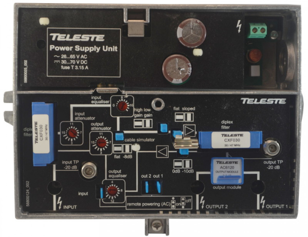
In reality, it’s not as daunting: except for a few minor differences, it’s all essentially the same as what we discussed above.
Firstly, there is a test tap at the input. It is necessary for monitoring the signal without disconnecting the cable from the amplifier's input and, consequently, without interrupting the broadcast.
Secondly, the newly introduced diplex filters, as well as the attenuator and output equalizer, are necessary for configuring DOCSIS channels. Therefore, in this article, I will only mention that the filters cut off the frequencies specified on them, which can become a problem if TV channels are broadcast on these frequencies. Fortunately, the manufacturer offers them with different values, and replacing them when necessary is not difficult.

The knobs (as well as the jumper introducing a -10 dB attenuation) only affect the return channel and cannot alter the television signal in any way.
The remaining three jumpers introduce us to such technology as remote power supply..
When designing buildings, amplifiers are often placed in locations where there may be issues with supplying electricity from distribution panels. Additionally, each "plug-socket" pair, which also implies an automatic switch (which can be installed in the most unexpected places), represents a potential point of failure. In this regard, there is a possibility to power equipment directly through the coaxial cable. Moreover, as indicated on the power supply overlay, this can be either alternating or direct current with a very wide voltage range. So, these three jumpers allow for the flow of power current to the input, as well as to each of the two outputs separately, if we need to power the next amplifier in the cascade. When enabling the riser with subscribers, of course, voltage cannot be supplied to the output!
I have already mentioned in part that such systems use special trunk splitters:
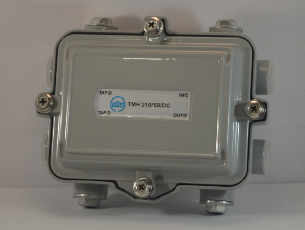
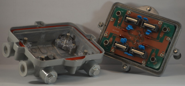
They use larger and more reliable components, and the massive casing provides heat dissipation and protection.
The power source in this case is a block with a built-in massive transformer:
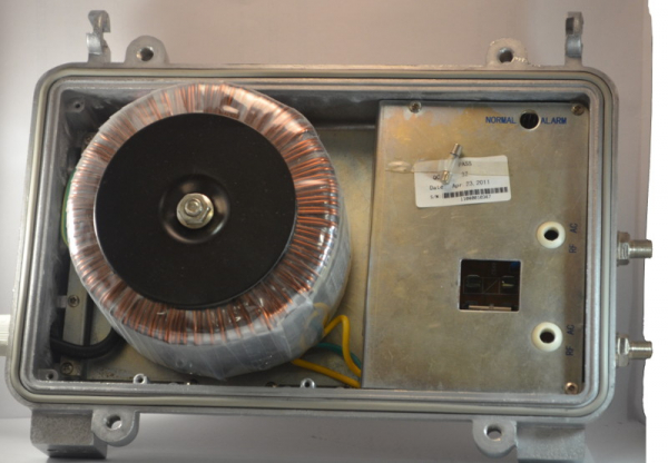
It is worth noting that despite the apparent efficiency of remote power schemes, amplifiers operating in this manner are less likely to experience outages without consequences during power supply failures in buildings. Additionally, when replacing them, technical personnel must search for and disconnect the power to the unit itself to avoid working with live cables, which means that while replacing a single amplifier without a signal, the entire building remains offline. For the same reason, a test outlet is necessary at the input of such amplifiers; otherwise, one would have to work with the cable under voltage.
It would be interesting to hear from colleagues how common remote power systems are. Please let us know in the comments if you use them.
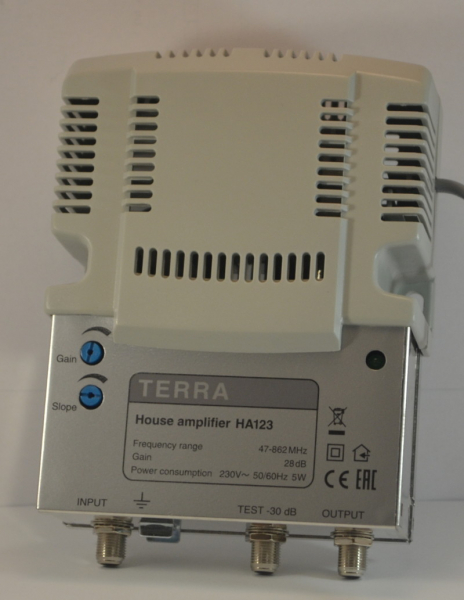
If you need to connect a large number of televisions within an apartment or office, you may encounter insufficient levels after a chain of splitters. In such cases, it is necessary to install an amplifier on the subscriber's premises, for which small devices with minimal settings and lower levels of amplification are used.
For example, one like this:
Source: habr.com
