

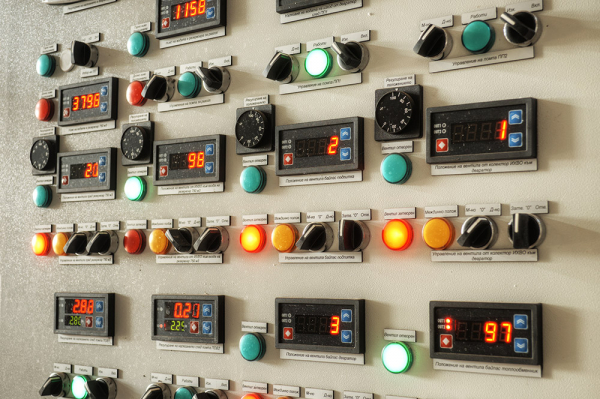
Many of you may know or have even seen how large automated objects, such as a nuclear power plant or a factory with numerous technological lines, are managed: the main actions often take place in a large room filled with screens, lights, and control panels. This management complex is commonly referred to as the MCS — master control station for overseeing the production facility.
You may be curious about how all this works from the hardware and software perspectives, and how these systems differ from familiar personal computers. In this article, we will delve into how various data flows to the MCS, how commands are sent to the equipment, and what is needed to manage a compressor station, a propane production facility, an automobile assembly line, or even a sewage pumping station.
The lower level or field bus — where everything begins
This vague set of terms used by the uninitiated refers to the means of communication between microcontrollers and the connected equipment, such as input-output modules or measuring devices. This communication channel is typically called the 'field bus' because it is responsible for transmitting data to the controller that comes from the 'field'.
'Field' is a deep professional term signifying that certain equipment (such as sensors or actuators) that the controller interacts with is located far away, in the outdoors, in the fields, under the cover of night. It doesn't matter if the sensor might be positioned half a meter from the controller and measuring, say, the temperature in an automation cabinet; it is still considered to be 'in the field'. Most often, signals from sensors arriving at input-output modules do traverse distances from dozens to hundreds of meters (or sometimes more), gathering information from remote sites or equipment. This is precisely why the bus through which the controller receives values from these sensors is usually referred to as the field bus, or less commonly, the lower level bus or industrial bus.
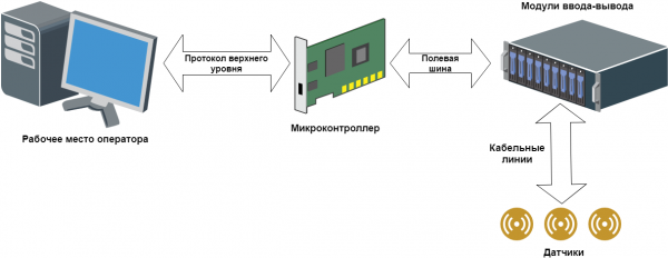
General scheme of industrial facility automation
Thus, the electrical signal from the sensor travels a certain distance through cable lines (often through standard copper cables with a number of conductors), to which several sensors are connected. The signal then reaches a processing module (input-output module), where it is converted into a digital language that the controller can understand. Subsequently, this signal is transmitted directly to the controller via the fieldbus, where it undergoes final processing. The logic of the microcontroller itself is built on such signals.
Top Level: from a garland to a whole workstation
The top level refers to everything that a typical operator controlling the technological process can touch. In the simplest case, the top level consists of a set of lights and buttons. The lights signal to the operator about certain events occurring in the system, while the buttons are used to send commands to the controller. Such a system is often called a "garland" or "Christmas tree" because it looks very similar (as can be seen in the photograph at the beginning of the article).
If the operator is luckier, they might have an operator panel as the top level—a kind of flat-panel computer that somehow receives data for display from the controller and outputs it to the screen. This panel is usually mounted on the automation cabinet itself, so interaction with it typically requires standing, which can cause inconvenience; additionally, the quality and size of the image on small-format panels often leaves much to be desired.
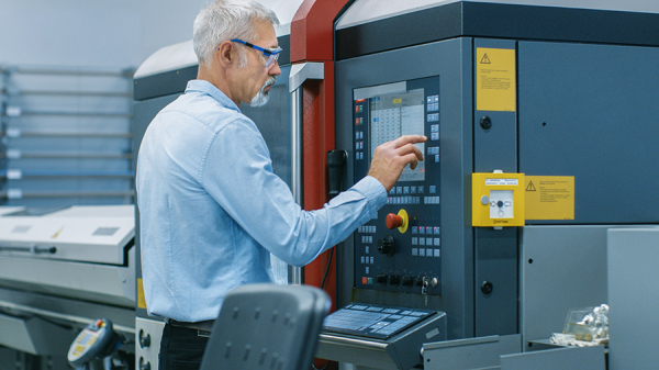
And finally, the unprecedented generosity attraction—a workstation (or even several duplicates), which is an ordinary personal computer.
The upper-level equipment must interact in some way with the microcontroller (otherwise, why is it needed?). For such interaction, upper-level protocols and some transmission medium, such as Ethernet or UART, are used. In the case of the "Christmas tree," no such complexities are needed; the lights are turned on using standard physical lines, without any sophisticated interfaces or protocols.
In general, this upper layer is less interesting than the fieldbus, since this upper layer may not exist at all (the operator has nothing to view there; the controller will figure out what needs to be done).
"Ancient" data transmission protocols: Modbus and HART
Few know, but on the seventh day of creation, God didn't rest, but instead created Modbus. Alongside the HART protocol, Modbus is perhaps the oldest industrial data transmission protocol, having originated back in 1979.
Initially, a serial interface was used for transmission, and later Modbus was implemented over TCP/IP. It is a synchronous master-slave protocol, based on a request-response principle. The protocol is quite heavyweight and slow, with the exchange speed depending on the characteristics of the receiver and transmitter, but usually, it takes nearly hundreds of milliseconds, especially in the implementation through a serial interface.
Moreover, the Modbus data transmission register is 16 bits, which immediately imposes limitations on the transmission of real and double types. They are either sent in parts or with a loss of precision. However, Modbus is still widely used in cases where high-speed exchange is not necessary and loss of transmitted data is not critical. Many manufacturers of various devices enjoy expanding the Modbus protocol in their unique and very original ways, adding non-standard functions. Therefore, this protocol has numerous mutations and deviations from the norm, but it still successfully exists in the modern world.
The HART protocol has also been around since the eighties; it is an industrial data exchange protocol over a two-wire current loop, which directly connects 4-20 mA sensors and other devices that support the HART protocol.
Special devices called HART modems are used for HART line connections. There are also converters that provide the user with, for example, the Modbus protocol at the output.
HART is notable for its ability to transmit both analog signals from 4-20 mA sensors and the digital signal of the protocol itself, allowing the digital and analog parts to be combined in one cable line. Modern HART modems can connect to the controller's USB port, connect via Bluetooth, or even use the older method through a serial port. A decade ago, a wireless standard called WirelessHART, working in the ISM band, emerged similarly to Wi-Fi.
The second generation of protocols is somewhat less industrial buses like ISA, PCI(e), and VME.
Replacing the Modbus and HART protocols are semi-industrial buses such as ISA (MicroPC, PC/104) or PCI/PCIe (CompactPCI, CompactPCI Serial, StacPC), as well as VME.
We have entered the era of computing devices with a universal data bus that allows for the connection of various boards (modules) for processing a unified signal. Typically, the processor module (the computer) is inserted into what is known as a chassis, which facilitates bus interaction with other devices. The chassis, or as true automators like to call it, a ‘crate’, is supplemented with necessary input-output boards: analog, discrete, interface, etc., or all of this is stacked in a sandwich-like structure without a chassis—one board above another. The data exchange on the bus (ISA, PCI, etc.) occurs with the processor module, which thus obtains information from the sensors and implements certain logic.
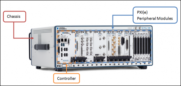
Controller and input-output modules in a PXI chassis on the PCI bus. Source:
Everything is fine with these ISA, PCI(e), and VME buses, especially for their time: the exchange speed is not disappointing, and the system components are located within a single chassis, compact and convenient. While hot-swapping input-output boards may not be possible, there isn't a strong desire for it just yet.
However, there is a downside, and not just one. Building a distributed system in this configuration is quite complex; the bus is local, and something needs to be devised for data exchange with other subordinate or peer nodes, like Modbus over TCP/IP or some other protocol; in general, there are few conveniences. And the second not-so-pleasant thing: input-output boards usually require some standardized signal at the input, and they lack galvanic isolation from field equipment, so you need to create a complex setup of various conversion modules and intermediate circuitry, which significantly complicates the component base.
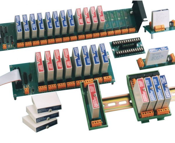
Intermediate signal conversion modules with galvanic isolation. Source:
"What about the exchange protocol over the industrial bus?" — you may ask. Well, there is none. In this implementation, the signal travels from the sensors to signal converters over cable lines, the converters output voltage to discrete or analog input-output boards, and data from the board is read via input/output ports using the operating system. And there are no specialized protocols.
How modern industrial buses and protocols work
What's next? By today, the classic ideology of automated system construction has changed a bit. A multitude of factors have played a role, starting from the necessity of making automation convenient, and ending with the trend towards distributed automated systems with nodes that are remote from each other.
It can be said that there are currently two main concepts for building automation systems: localized and distributed automated systems.
In the case of localized systems, where data collection and management are centralized in one specific location, the concept of a set of input-output modules interconnected by a common fast bus is in demand, including a controller with its own exchange protocol. Typically, the input-output modules include both a signal converter and galvanic isolation (although, of course, this is not always the case). This means that the end user only needs to understand what types of sensors and mechanisms will be present in the automated system, count the required number of input-output modules for different signal types, and connect them into a single common line with the controller. In this case, each manufacturer usually employs their preferred exchange protocol between the input-output modules and the controller, and there can be many variations here.
In the case of distributed systems, everything said regarding localized systems applies, but it is also important that individual components, such as a set of input-output modules plus an information collection and transmission device— a rather simple microcontroller situated somewhere in a booth in the field next to a valve that regulates oil— can interact with similar nodes and the main controller over a long distance with effective exchange speed.
How do developers choose a protocol for their project? All modern exchange protocols provide fairly high performance, thus the choice of a particular manufacturer is often not determined by the speed of communication over the industrial bus. The actual implementation of the protocol is also not that critical because, from the system developer's perspective, it will still be a black box that provides a certain internal exchange structure and is not designed for external intervention. More often than not, attention is paid to practical characteristics: the performance of the computing unit, the convenience of applying the manufacturer's concept to the assigned task, the availability of the required types of input-output modules, the possibility of hot-swapping modules without breaking the bus, etc.
Popular equipment suppliers offer their own implementations of industrial protocols: for example, the well-known company Siemens develops its series of Profinet and Profibus protocols, B&R provides the Powerlink protocol, and Rockwell Automation offers the EtherNet/IP protocol. A domestic solution in this list of examples is the FBUS protocol version from the Russian company Fastwel.
There are also more universal solutions that are not tied to a specific manufacturer, such as EtherCAT and CAN. We will detail these protocols further in the continuation of the article and explore which of them are better suited for specific applications: automotive and aerospace industries, electronics manufacturing, positioning systems, and robotics. Stay tuned!
Source: habr.com
