


The boundary between the optical medium and the coaxial cable is the optical receiver. In this article, we will examine their design and settings.
Contents of the article series
- Part 7: Optical receivers
- Part 8: Optical backbone network
- Part 9: Headend
- Part 10: Troubleshooting in the CATV network
The task of the optical receiver is to transfer the signal from the optical medium to the electrical one. In its simplest form, this can be done using a passive device that impresses with its simplicity:
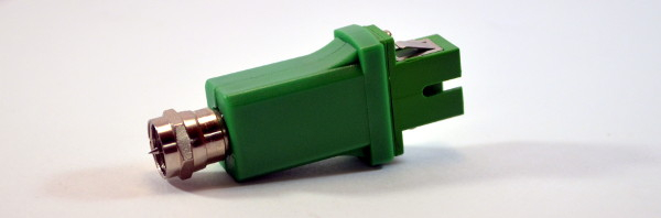
However, this engineering marvel provides rather mediocre signal parameters: with an optical signal level of -1 to -2 dBm, the output parameters barely meet the standards, and increasing the signal significantly raises the noise.
To ensure the quality of the delivered signal in an FTTB architecture, more complex devices are required:

The receivers found in our network include Vector Lambda, Telmor MOB, and the domestic Planar.
All of them differ from their passive counterpart with more complex circuitry, including filters and amplifiers, ensuring a reliable signal reaches the subscriber. Let's take a closer look at them:
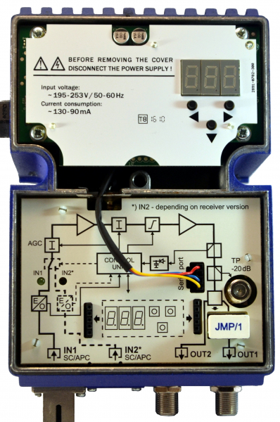
The Telmor optical receiver has a panel inside showing the structural diagram. This diagram is typical for optical receivers.
The required level of optical signal is usually from -10 to +3 dBm, with -1 dBm being the optimal value during design and commissioning: it provides a comfortable margin in case of transmission line degradation, and at the same time, a lower level creates less noise as it passes through the equipment chains.
The built-in AGC (Automatic Gain Control) circuit in the optical receiver is responsible for maintaining the output within specified parameters by regulating the level of the incoming signal. This means that if, for any reason, the optical signal suddenly changes significantly, but stays within the operational range of the AGC (approximately from 0 to -7 dBm), the receiver will reliably output to the coaxial network the signal level that was set during adjustment. For particularly critical cases, devices with two optical inputs are available, each monitored and operable both manually and automatically.
All active optical receivers contain an amplification stage, which also provides the capability to adjust the slope and level of the output signal.
Management of optical receivers
To configure signal parameters and to change and control built-in service functions within the receivers, simple control buttons are usually present. In the MOB, shown in the photo above, this is a separate board that can be optionally installed in the case. Alternatively, a quick-release board is offered, which is installed only during settings adjustment to the ports on the main board. In practice, this is not very convenient, of course.
The control panel allows you to set the values of the input attenuator (increasing which reduces the output signal according to the gain factor), turn on or off (as well as set fixed values for) AGC, set slope parameters, and configure the Ethernet interface.
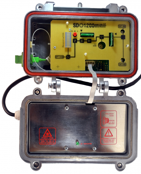
The Chelyabinsk OP Planar has a clear optical signal level indicator, and settings are made simply: with a knob and by changing inserts that alter the characteristics of the amplifier stage. The power supply is located under a hinged cover.
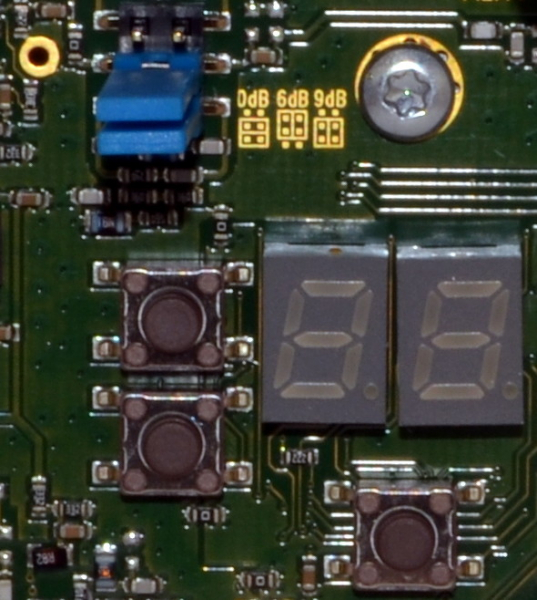
Designed in a 'tech-porn' style, the OP Vector Lambda features a two-digit screen and only three buttons.
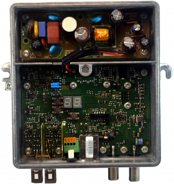
To distinguish positive values from negative ones, this OP displays negative values with all segments, while a positive zero and +1 are shown as half the height of the screen. For values above +1.9, it simply writes 'HI'.
Such control buttons are convenient for on-site adjustments, but to enable remote monitoring and control, almost all receivers have an Ethernet port. The web interface allows for monitoring and changing parameters, and integration with monitoring systems supports polling via SNMP.
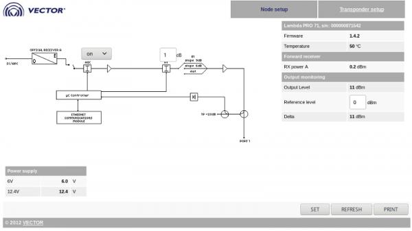
Here we see the same typical structural scheme of the OP, which has the ability to change the parameters of AGC and the attenuator. However, the slope on this OP is set only with jumpers on the board and has three fixed positions.
Next to the diagram, important control parameters are displayed: levels of incoming and outgoing signals, as well as voltage values received from the built-in power supply unit. 99% of failures in such OPs occur after degradation of these voltages, so it is advisable to monitor them to prevent malfunctions.
The term Transponder here refers to the IP interface, and this tab contains settings for the address, mask, and gateway — nothing interesting.
Bonus: Terrestrial TV Reception
This isn't related to the series theme, but I will briefly talk about terrestrial TV reception. Why now? Simply put, when considering the network of an apartment building, the type of signal source in a coaxial distribution network determines whether the network is cable or terrestrial.
In the absence of fiber optic, a terrestrial broadcasting receiver, such as the Terra MA201, can be installed instead of the OP with a KTV signal:
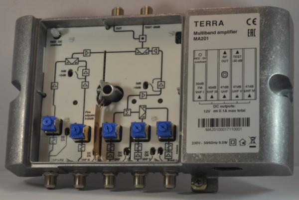
Several antennas (usually three) are connected to the input ports of the receiver, each providing reception for its frequency range.
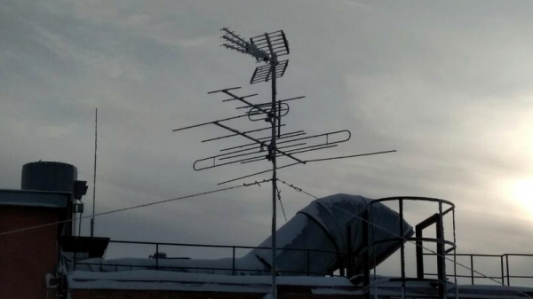
With the transition to digital broadcasting, this necessity is eliminated, as digital multiplexes are broadcast in a single range.
For each antenna, sensitivity can be adjusted to reduce noise, and if necessary, remote powering can be supplied to the built-in amplifier in the antenna. The signal then goes through an amplification cascade and is summed. Adjusting the output level involves turning off stages of the cascade, and tilt adjustment is not provided at all: the desired spectrum shape can be obtained by adjusting the sensitivity of each antenna individually. If there are kilometers of coaxial cable behind such a receiver, then to combat attenuation, amplifiers are installed and tuned, similar to those used in cable networks.
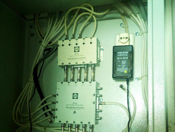
If desired, signal sources can be combined: creating a single network that includes cable, terrestrial, and also satellite signals. This is done using multiswitches — devices that allow for summing and distributing signals from various sources.
Source: habr.com
