


For many years, optical medium has been the foundation of data transmission. It's hard to imagine a tech enthusiast who isn't familiar with these technologies, but some brief explanation is necessary in my series of articles.
Contents of the article series
- Part 9: Headend
- Part 10: Troubleshooting in the CATV network
To give a complete picture, let me briefly explain a couple of basic things (please don’t throw anything at me; this is for those who are completely new to the topic): optical fiber is glass that has been drawn into a thread thinner than a hair. A beam formed by a laser travels through it, which (like any electromagnetic wave) has a specific frequency. For convenience, discussions about optics typically use the inverse of frequency, which is wavelength, measured in nanometers in the optical range. For cable television signals, a wavelength of λ=1550nm is usually employed.
The segments of the main line are connected by welding or connectors. You can read more about this in . I’ll just mention that in CATV networks, angled APC polish is almost always used.
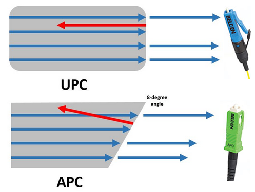
Image from fiber-optic-solutions.com
It introduces slightly more attenuation than straight polish but possesses a very important property: the signal reflected at the connector does not travel along the same axis as the main signal, thereby exerting less influence on it. For digital transmission systems with built-in redundancy and recovery algorithms, this might seem insignificant, but the television signal began its journey as an analog signal (including in fiber optics), where it is very critical: everyone remembers the double images or drifting visuals on older TVs during poor reception. Similar wave phenomena occur both in the air and in cables. Although the digital television signal has improved resistance to interference, it still lacks many advantages of packet data transmission and can also suffer at the physical level, but it can no longer be recovered through retransmission.
To transmit a signal over a significant distance, a high level is required, so amplifiers are essential in the chain. In CATV systems, optical signals are amplified using erbium-doped fiber amplifiers (EDFA). The operation of this device serves as a perfect example of how any sufficiently advanced technology is indistinguishable from magic. In simple terms, as the beam passes through the fiber doped with erbium, conditions are created where each photon of the original emission generates two clones. Such devices are used in all data transmission systems over considerable distances. They are certainly not cheap. Therefore, in cases where signal amplification to a significant degree is not required and strict noise limits are not needed, signal regenerators are used:
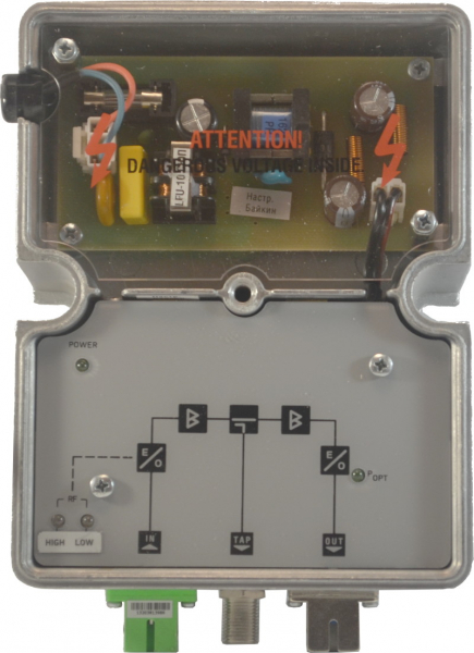
This device, as seen in the structural diagram, performs a double conversion of the signal between optical and electrical media. This design allows for the wavelength of the signal to be changed if necessary.
Manipulations like amplification and regeneration of the signal are necessary not only to compensate for the kilometers of cable loss. The greatest losses occur when dividing the signal between the branches of the network. Division is carried out using passive devices, which can vary in the number of outputs depending on the need, and can divide the signal both symmetrically and asymmetrically.
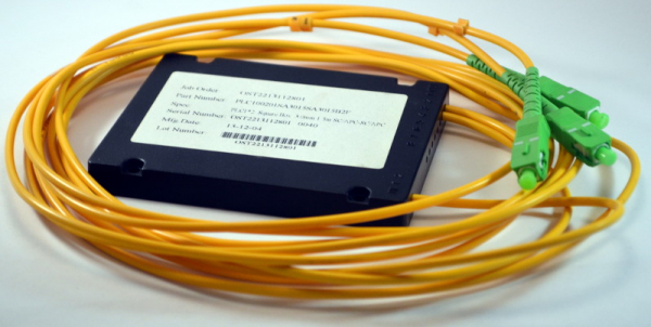
Internally, the splitter consists of either fibers connected to the side surfaces or is etched, like traces on a printed circuit board. For deeper understanding, I recommend articles about and splitters respectively. The more outputs a splitter has, the greater attenuation it introduces into the signal.
If filters are added to the splitter to separate beams with different wavelengths, we can transmit two signals simultaneously in one fiber.
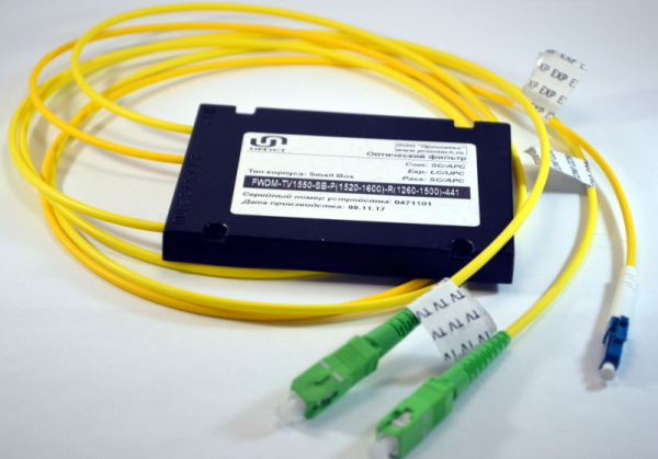
This is the simplest option for multiplexing in optics — FWDM. By connecting cable TV and Internet equipment to the TV and Express inputs respectively, we obtain a mixed signal at the common output COM, which can be transmitted over a single fiber. On the other side, it can be divided again between an optical receiver and a switch, for example. This occurs in a manner similar to how a glass prism creates a rainbow from white light.
To ensure redundancy of the optical signal, in addition to optical receivers with two inputs that I mentioned an electromechanical relay can be used, which can switch from one source to another based on specified signal parameters.
In the event of one fiber degrading, the device will automatically switch to another. The switching time is less than a second, so for the subscriber, it appears at worst as a handful of artifacts on the digital television image, which immediately disappear with the next frame.
Source: habr.com
