

In I outlined a network automation framework. Feedback from some people indicates that even this initial approach to the problem has clarified certain issues. This makes me very happy because our goal in this cycle is not to coat Ansible with Python scripts but to build a system.
This framework establishes the order in which we will address the question.
And the network virtualization, which this issue is dedicated to, does not really fit into the theme of ADSM, where we discuss automation.
But let's look at it from a different angle.
For a long time, one network has been used by many services. In the case of a telecommunications operator, this includes 2G, 3G, LTE, broadband, and B2B, for example. For data centers: connectivity for different clients, the Internet, block storage, object storage.
And all services require isolation from each other. That’s how overlay networks came into being.
And all services don’t want to wait for a person to configure them manually. That’s where orchestrators and SDN emerged.
The first approach to systematic network automation, or rather a part of it, has long been undertaken and implemented in various places: VMWare, OpenStack, Google Compute Cloud, AWS, Facebook.
That’s what we will analyze today.
Content
- Reasons
- Terminology
- Underlay — physical network
- Overlay — virtual network
- Overlay from the ToR
- Overlay from the host
- Using Tungsten Fabric as an example
- Communication within a single physical machine
- Communication between VMs located on different physical machines
- Access to the outside world
- FAQ
- Conclusion
- Useful links
Reasons
And since we are on this topic, it is worth mentioning the prerequisites for network virtualization. In fact, this process didn’t start yesterday.
You have probably heard many times that the network has always been the most inert part of any system. And this is true in every sense. The network is the basis upon which everything relies, and making changes to it is quite difficult — services cannot tolerate if the network goes down. Often, taking one node offline can disrupt a significant portion of applications and impact many clients. Partly for this reason, the network team may resist any changes — because it’s working somehow now (we may not even know how), and now we need to set something new up, and it’s uncertain how it will affect the network.
To avoid waiting for network operators to configure VLANs and to avoid having to set up services on every node in the network, people invented the use of overlays — layered networks — which come in a vast array: GRE, IPinIP, MPLS, MPLS L2/L3VPN, VXLAN, GENEVE, MPLSoverUDP, MPLSoverGRE, etc.
Their appeal lies in two simple things:
- Only the end nodes are configured — transit nodes need not be touched. This significantly speeds up the process and sometimes even allows the network infrastructure department to be excluded from the onboarding of new services.
- The load is hidden deep within the headers — transit nodes don't need to know anything about it, about the addressing of hosts, or the routes of the overlay network. This means less information has to be stored in the tables, allowing for simpler/cheaper devices.
In this not entirely complete issue, I do not plan to cover all possible technologies but rather to describe the framework for how overlay networks function in data centers.
The entire series will describe a data center consisting of rows of identical racks, in which identical server hardware is installed.
On this hardware, virtual machines/containers/serverless are launched to implement services.
Terminology
In the cycle proxy server I will refer to the program that implements the server side of client-server communication.
Physical machines in racks will be called servers do not from now on.
A physical machine is an x86 computer installed in a rack. The most commonly used term hostwill be "machine" oran application running on a physical machine that emulates physical resources where Virtual Machines run. Sometimes in literature and online, the term "hypervisor" is used as a synonym for "host."an operating system running on a physical machine on top of the hypervisor. For us in this cycle, it is not very important whether it is actually a virtual machine or just a container. We will refer to it as " host.
Hypervisor VM
Virtual machine Tenantis a broad term that in this article I will define as a separate service or a specific client.«
Multi-tenancy or multi-tenant architecture refers to the use of the same application by different clients/services. Here, the isolation of clients from each other is achieved through the application architecture rather than through separately launched instances.
ToR — Top of the Rack switch or multi-tenancy — the use of the same application by different clients/services. In this case, client isolation is achieved through the application's architecture rather than through separately launched instances.
ToR — Top of the Rack switch — a rack-mounted switch to which all physical machines are connected.
In addition to ToR topology, various providers practice End of Row (EoR) or Middle of Row (though the latter is rarely used, and I haven't encountered the abbreviation MoR).
Underlay network or the underlay network is the physical network infrastructure: switches, routers, cables.
Overlay network or overlay network — a virtual network of tunnels operating on top of the physical one.
L3 fabric or IP fabric — a wonderful invention of humanity that allows one to avoid repeating STP and learning TRILL during interviews. A concept where the entire network, down to the access level, is entirely L3, without VLANs and, as a result, huge sprawling broadcast domains. We'll unpack the term 'fabric' in the next part.
SDN — Software Defined Network. Hardly needs an introduction. It's an approach to network management where changes to the network are performed not by a person but by a program. It usually means taking the Control Plane out of the end network devices and placing it on a controller.
NFV — Network Function Virtualization — virtualization of network devices, implying that some network functions can be run as virtual machines or containers to accelerate the deployment of new services, organize Service Chaining, and simplify horizontal scalability.
VNF — Virtual Network Function. A specific virtual device: router, switch, firewall, NAT, IPS/IDS, etc.
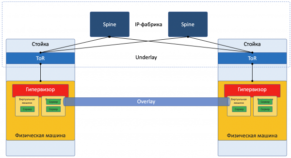
I am currently intentionally simplifying the description to a specific implementation to avoid confusing the reader too much. For a more thoughtful read, I refer you to the section . Additionally, Roma Gorgi, who criticizes this article for inaccuracies, promises to write a separate issue on server and network virtualization technologies that is more in-depth and detail-oriented.
Most networks today can clearly be divided into two parts:
Underlay — a physical network with a stable configuration.
Overlay — an abstraction over Underlay for tenant isolation.
This is true for both the datacenter case (which we will discuss in this article) and for ISPs (which we will not discuss because it was already covered in ). With enterprise networks, of course, the situation is somewhat different.
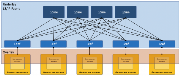
A diagram focusing on the network:
Underlay
Underlay is a physical network: hardware switches and cables. Devices in the underlay know how to reach physical machines.
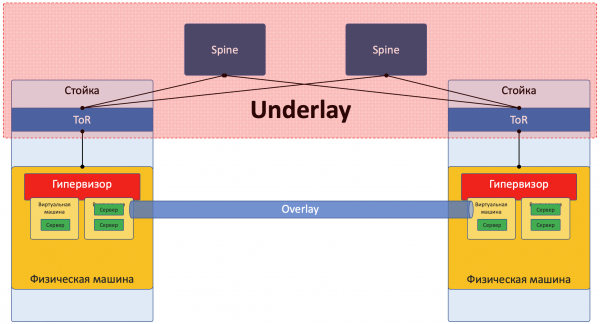
It relies on standard protocols and technologies. Not least because hardware devices still operate on proprietary software that does not allow chip programming or the implementation of their own protocols; therefore, compatibility with other vendors and standardization are required.
However, companies like Google can afford the development of their own switches and the abandonment of commonly accepted protocols. But LAN_DC is not Google.
Underlay changes relatively rarely because its task is to provide basic IP connectivity between physical machines. Underlay knows nothing about the services, clients, or tenants running on top of it; it only needs to deliver packets from one machine to another.
An example of an Underlay might be:
- IPv4+OSPF
- IPv6+ISIS+BGP+L3VPN
- L2+TRILL
- L2+STP
The Underlay network is configured in the classic way: CLI/GUI/NETCONF.
Manually, with scripts, proprietary utilities.
The next article in the series will delve into Underlay in more detail.
Overlay
Overlay is a virtual network of tunnels stretched over Underlay, allowing one client’s VMs to communicate with each other, while ensuring isolation from other clients.
Client data is encapsulated in tunnel headers for transmission over a shared network.
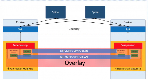
Thus, one client’s VMs (from one service) can communicate with each other through Overlay, even unaware of the actual path the packet takes.
An example of an Overlay might be, as I mentioned earlier:
- GRE tunnel
- VXLAN
- EVPN
- L3VPN
- GENEVE
The Overlay network is usually set up and maintained through a central controller. From it, the configuration, Control Plane, and Data Plane are delivered to devices responsible for routing and encapsulating client traffic. A little we will explore this with examples.
Yes, this is SDN in its purest form.
There are two fundamentally different approaches to organizing an Overlay network:
- Overlay from the ToR
- Overlay from the host
Overlay from the ToR
Overlay can start at the access switch (ToR) located in the rack, as happens, for example, in the case of a VXLAN fabric.
This is a time-tested mechanism used in ISP networks, and all networking vendors support it.
However, in this case, the ToR switch must be able to separate different services accordingly, and the network administrator must collaborate to some extent with virtual machine administrators and make changes (even if automatically) to the device configuration.
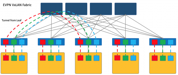
Here I will refer the reader to the article on our old friend .
, there will be a list of resources for preparation for the Azure Dev/Infra/Architecture exam. which describes in detail the approaches to building a DC network with an EVPN VXLAN fabric.
And for a more comprehensive immersion into the realities, you can read Cisco's book .
I note that VXLAN is just a method of encapsulation, and tunnel termination can occur not on the ToR, but on the host, as happens in the case of OpenStack, for example.
However, a VXLAN fabric where the overlay begins on the ToR is one of the established designs of overlay networks.
Overlay from the host
Another approach is to start and terminate tunnels on the end hosts.
In this case, the underlay network remains as simple and static as possible.
And the host itself will handle all necessary encapsulations.
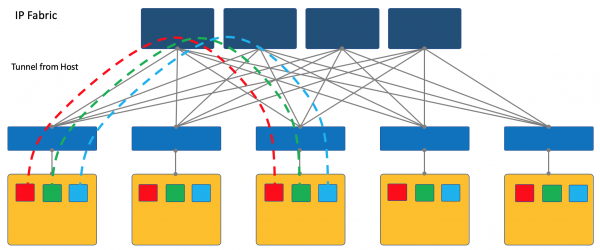
To do this, it will certainly be necessary to run a special application on the hosts, but it's worth it.
Firstly, running a client on a Linux machine is easier or, let's say, even possible—whereas on a switch, you will likely have to resort to proprietary SDN solutions, which undermines the idea of multivendor compatibility.
Secondly, in this case, the ToR switch can be kept as simple as possible, both in terms of the Control Plane and the Data Plane. Indeed, with an SDN controller, it doesn't need to communicate, and storing the networks/ARPs of all connected clients isn't needed either—it is sufficient to know the IP address of the physical machine, which greatly simplifies the switching/routing tables.
In the ADSM series, I choose the overlay approach from the host—further, we will only discuss this, and we will not return to the VXLAN fabric.
It's easiest to consider this with examples. As a test subject, we will use the open-source SDN platform OpenContrail, now known as .
At the end of the article, I will present some thoughts on the analogy with OpenFlow and OpenvSwitch.
Using Tungsten Fabric as an example
On each physical machine, there is vRouter — a virtual router that is aware of the networks connected to it and which clients they belong to — essentially a PE router. For each client, it maintains an isolated routing table (read VRF). The vRouter performs overlay tunneling.
A bit more about vRouter is at the end of the article.
Each VM located on the hypervisor is connected to the vRouter of that machine via .
TAP — Terminal Access Point — a virtual interface in the Linux kernel that allows for network communication.
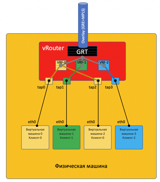
If there are multiple networks behind the vRouter, a virtual interface is created for each of them, assigned an IP address — which will be the default gateway address.
All networks of one client are placed in one VRF (one table), while different ones are in different tables.
I want to note that it's not that simple, and I will send the curious reader to the end of the article..
For vRouters to communicate with each other, and consequently the VMs behind them, they exchange routing information via the SDN controller.
To connect to the outside world, there is an exit point from the matrix — the virtual network gateway VNGW — Virtual Network GateWay (this term is mine).
Now let's look at communication examples — this will clarify things.
Communication within a single physical machine
VM0 wants to send a packet to VM2. For now, let's assume these VMs belong to the same client.
Data Plane
- VM-0 has a default route through its interface eth0. The packet is sent there.
This interface eth0 is actually virtually connected to the virtual router vRouter via the TAP interface tap0. - The vRouter analyzes which interface the packet arrived on, i.e., which client (VRF) it belongs to, and checks the recipient's address against that client's routing table.
- Finding that the recipient is on the same machine but at a different port, the vRouter simply sends the packet there without any additional headers — in this case, the vRouter already has an ARP entry.
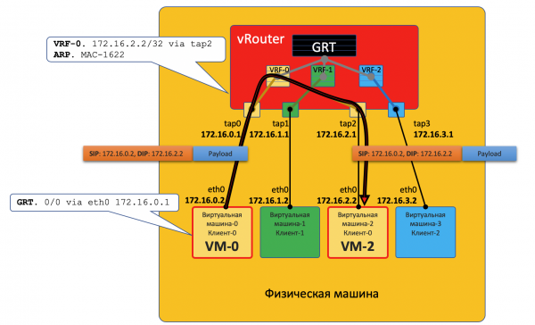
In this scenario, the packet does not enter the physical network — it is routed within the vRouter.
Control Plane
When starting the virtual machine, the hypervisor informs it:
- Its own IP address.
- The default route — through the IP address of the vRouter in this network.
The hypervisor informs the vRouter via a special API:
- That a virtual interface needs to be created.
- What Virtual Network it needs to create (for the VM).
- To which VRF to bind it (VN).
- The static ARP entry for this VM - which interface its IP address is associated with and to which MAC address it is tied.
Once again, the real procedure of interaction is simplified for the sake of understanding the concept.
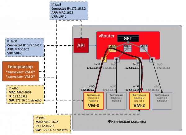
Thus, all VMs of a single client on this machine see the vRouter as directly connected networks and can route between them independently.
However, VM0 and VM1 belong to different clients and therefore reside in different vRouter tables.
Whether they can communicate directly depends on the vRouter settings and network design.
For instance, if VMs of both clients use public addresses, or NAT occurs on the vRouter itself, direct routing on the vRouter can be enabled.
In the opposite case, address space overlap may occur – a NAT server is needed to obtain a public address – this resembles accessing external networks, which will be discussed below.
Communication between VMs located on different physical machines
Data Plane
- The start is exactly the same: VM-0 sends a packet addressed to VM-7 (172.17.3.2) based on its default.
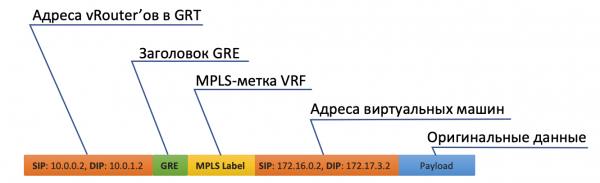
- The vRouter receives it and this time sees that the recipient is on a different machine and is accessible through Tunnel0.
- First, it attaches an MPLS label that identifies the remote interface so that on the other side, the vRouter can determine where to place this packet without additional lookups.
- For Tunnel0, the source is 10.0.0.2, and the destination is 10.0.1.2.
The vRouter adds GRE (or UDP) headers and a new IP to the original packet. - In the routing table, the vRouter has a default route through ToR1 10.0.0.1. It sends it there.

- ToR1, as a participant in the underlay network, knows (for example, via OSPF) how to reach 10.0.1.2 and sends the packet along that route. Note that ECMP is involved here. In the illustration, there are two next hops, and different flows will be distributed among them based on hashes. In a real fabric, there would be more like 4 next hops.
At the same time, it does not need to know what is under the external IP header. So actually, under IP, it may be a sandwich of IPv6 over MPLS over Ethernet over MPLS over GRE over and over again.
- Consequently, on the receiving side, the vRouter strips off GRE and, by the MPLS label, understands to which interface this packet should be forwarded, unpacks it, and sends it to the recipient in its original form.
Control Plane
When the machine is powered up, everything described above occurs.
And plus, the following happens:
- For each client, the vRouter allocates an MPLS label. This is a service label for L3VPN, which clients will use to be separated within the same physical machine.
In fact, the MPLS label is always allocated by the vRouter without exception—after all, it is unknown in advance whether the machine will interact only with other machines behind the same vRouter, and that is most likely not the case.
- The vRouter establishes a connection with the SDN controller using the BGP protocol (or a similar one—in the case of TF, it’s XMPP 0_o).
- Through this session, the vRouter informs the SDN controller of the routes to the connected networks:
- Network address
- Encapsulation method (MPLSoGRE, MPLSoUDP, VXLAN)
- Client MPLS label
- Its IP address as the nexthop
- The SDN controller receives such routes from all connected vRouters and reflects them to others. In other words, it acts as a Route Reflector.
The same happens in the opposite direction.
The overlay can change every minute. This is roughly how it operates in public clouds, where clients regularly start and stop their virtual machines.
The central controller takes on all the complexities of maintaining configuration and controlling switching/routing tables on the vRouter.
In rough terms, the controller connects with all vRouters via BGP (or a similar protocol) and simply passes along routing information. BGP, for example, already has an Address-Family for transmitting the encapsulation method. or .
At the same time, the configuration of the Underlay network does not change in any way, which, by the way, is significantly more complex to automate, and can be broken with a careless move.
Access to the outside world
Somewhere, the simulation must end, and it's necessary to step out of the virtual world into the real one. A gateway for that is needed.
Two approaches are practiced:
- A hardware router is installed.
- Some appliance is launched that implements router functions (yes, yes, after SDN, we also encountered VNF). Let's call it a virtual gateway.
The advantage of the second approach is its cheap horizontal scalability—if there's a lack of power, another virtual machine with a gateway is launched. On any physical machine, without the need to look for available racks, units, power output, buy the hardware itself, transport it, install it, connect it, configure it, and then also replace its faulty components.
The downsides of a virtual gateway are that a unit of physical router is still exponentially more powerful than a multi-core virtual machine, and its software, tailored to its hardware base, operates significantly more stably (none). It’s hard to deny the fact that the hardware-software complex simply works, requiring only configuration, whereas launching and maintaining a virtual gateway is a task for skilled engineers.
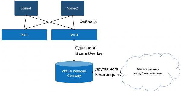
With one foot, the gateway looks into the Overlay virtual network, like a regular Virtual Machine, and can interact with all other VMs. At the same time, it can terminate networks of all clients and respectively perform routing between them.
With the other foot, the gateway looks into the backbone network and knows how to reach the Internet.
Data Plane
So the process looks like this:
- VM-0, having a default vRouter, sends a packet with a destination in the external world (185.147.83.177) to the eth0 interface.
- The vRouter receives this packet and performs a destination address lookup in the routing table—finding the default route through gateway VNGW1 via Tunnel 1.
It also sees that this is a GRE tunnel with SIP 10.0.0.2 and DIP 10.0.255.2, and it needs to first apply the MPLS label for this client, which VNGW1 expects. - The vRouter wraps the initial packet in MPLS, GRE headers, and a new IP, and sends it to the address ToR1 10.0.0.1 by default.
- The underlay network delivers the packet to gateway VNGW1.
- Gateway VNGW1 strips the tunneling GRE and MPLS headers, sees the destination address, consults its routing table, and understands that it is directed towards the Internet—thus through Full View or Default. It performs NAT translation if necessary.
- From VNGW to the border may be a regular IP network, which is unlikely.
It could be a classic MPLS network (IGP+LDP/Rsvp TE), or it could be a reverse fabric with BGP LU or a GRE tunnel from VNGW to the border over an IP network.
In any case, VNGW1 performs the necessary encapsulations and sends the initial packet towards the border.
The traffic in the reverse direction goes through the same steps in the opposite order.
- The border delivers the packet to VNGW1.
- It breaks it down, looks at the destination address, and sees that it is accessible via Tunnel1 (MPLSoGRE or MPLSoUDP).
- Accordingly, it applies the MPLS label, the GRE/UDP header, and a new IP, and sends it to its ToR3 10.0.255.1.
The tunnel destination address is the IP address of the vRouter behind which the target VM is located: 10.0.0.2. - The underlay network delivers the packet to the appropriate vRouter.
- The target vRouter removes GRE/UDP, identifies the interface based on the MPLS label, and sends the raw IP packet to its TAP interface associated with the VM's eth0.
Control Plane
VNGW1 establishes a BGP adjacency with the SDN controller from which it receives all routing information about clients: which IP address (vRouter) is associated with which client, and the MPLS label that identifies it.
Similarly, the SDN controller is informed of the default route with this client's label, indicating itself as the nexthop. Subsequently, this default route reaches the vRouters.
Route aggregation or NAT translation usually occurs at VNGW.
In the opposite direction, it delivers exactly this aggregated route to the session with the borders or Route Reflectors. From them, it receives the default route or Full-View, or something else.
In terms of encapsulation and traffic exchange, VNGW is indistinguishable from vRouter.
If we slightly broaden the scope, other network devices can be added to VNGW and vRouters, such as firewalls, traffic scrubbing or enrichment farms, IPS, and so on.
By sequentially creating VRFs and correctly announcing routes, the traffic can be made to loop as desired, which is referred to as Service Chaining.
Thus, the SDN controller acts as a Route Reflector among VNGW, vRouters, and other network devices.
In fact, the controller also passes down information about ACL and PBR (Policy Based Routing), causing individual traffic flows to follow paths different from what the route commands.
FAQ
Why do you always make a point of GRE/UDP?
Well, actually, this can be said to be specific to Tungsten Fabric — one can completely ignore it.
However, if we take it into account, TF, even when it was OpenContrail, supported both encapsulations: MPLS in GRE and MPLS in UDP.
UDP is advantageous because it's very easy to encode a hash function from the original IP+Proto+Port in its header's Source Port, which allows for load balancing.
In the case of GRE, unfortunately, there are only the external IP and GRE headers, which are identical for all encapsulated traffic, making load balancing difficult — few can look that deeply inside the packet.
Until recently, routers that could handle dynamic tunnels only worked with MPLSoGRE and have only just begun to support MPLSoUDP. Therefore, it's always necessary to make a note of the possibility of using two different encapsulations.
Fairness dictates that we note TF also fully supports L2 connectivity through VXLAN.
You promised to draw parallels with OpenFlow.
They indeed suggest themselves. The vSwitch in OpenStack performs very similar functions using VXLAN, which also has a UDP header.
In the Data Plane, they operate quite similarly, while the Control Plane significantly differs. Tungsten Fabric uses XMPP to deliver routing information to the vRouter, whereas OpenStack employs OpenFlow.
Can you elaborate more on vRouter?
It consists of two parts: vRouter Agent and vRouter Forwarder.
The first runs in the User Space of the host OS and communicates with the SDN controller by exchanging information about routes, VRF, and ACL.
The second implements the Data Plane — typically in Kernel Space, but can also run on SmartNICs — network cards with a CPU and a separate programmable switching chip, which helps alleviate the load on the host machine's CPU and makes the network faster and more predictable.
There is also a scenario where the vRouter is a DPDK application in User Space.
The vRouter Agent transmits the settings to the vRouter Forwarder.
What is a Virtual Network?
I mentioned earlier in the article about VRF, stating that each tenant is associated with their own VRF. And while this was sufficient for a superficial understanding of how the overlay network works, further clarifications are necessary in the next iteration.
Typically, in virtualization mechanisms, the Virtual Network entity (consider it a proper noun) is introduced separately from clients/tenants/virtual machines — quite a standalone entity. This Virtual Network can then be connected through interfaces to one tenant, another, two, or anywhere else. This is how Service Chaining is implemented, where traffic must pass through certain nodes in the required sequence, simply by creating and attaching Virtual Networks in the correct order.
Therefore, there is no direct correspondence between a Virtual Network and a tenant.
Conclusion
This is a rather superficial description of how an overlay virtual network works with a host and an SDN controller. However, no matter which virtualization platform you choose today, it operates in a similar manner, whether it’s VMWare, ACI, OpenStack, CloudStack, Tungsten Fabric, or Juniper Contrail. They will differ in terms of encapsulation types and headers, as well as protocols for delivering information to end network devices, but the principle of a software-defined overlay network operating atop a comparatively simple and static underlay network remains unchanged.
It can be said that, as of today, the domain of private cloud creation has been won by SDN based on overlay networks. However, this doesn’t mean that OpenFlow has no place in the modern world—it is used in OpenStack and in VMWare NSX, and as far as I know, Google employs it for configuring the underlay network.
Below, I've provided links to more detailed materials if you wish to study the issue further.
And what about our Underlay?
Well, not much at all. It has not changed throughout. All it needs to do in the case of an overlay with a host is to update routes and ARPs as vRouter/VNGW appear and disappear and to transport packets between them.
Let’s formulate a list of requirements for the Underlay network.
- It must support a certain routing protocol, in our case—BGP.
- It should have a wide bandwidth, preferably without oversubscription, so that packets aren’t lost due to congestion.
- Supporting ECMP is an integral part of the fabric.
- It must be able to provide QoS, including advanced features like ECN.
- Support for NETCONF is a future consideration.
I have devoted very little time to the operation of the Underlay network here. This is because I will focus on it in the following series, while we will only touch on Overlay in passing.
Clearly, I am severely limiting all of us by using a data center network built on a Clos fabric with pure IP routing and an overlay from the host as an example.
However, I am confident that any network with a design can be described in formal terms and automated. My aim here is simply to understand the approaches to automation, not to confuse everyone in general by solving the problem in broad terms.
Within the framework of ADSM, Roman Gorgy and I plan to publish a separate issue about the virtualization of computing resources and its interaction with network virtualization. Stay tuned.
Useful links
- .
- . 6 hours on Yandex.Cloud, which includes a discussion about the virtual network on TF.
- .
- . This covers the entire DC network, including Underlay, Overlay, approaches to multi-homing, and management.
Thanks
- — former host of the linkmeup podcast, now an expert in cloud platforms. Thanks for the comments and edits. We look forward to his upcoming in-depth article on virtualization.
- — my colleague and an expert in developing virtual networks. Thanks for the comments and edits.
- — my colleague and an expert in Tungsten Fabric. Thanks for the comments and edits.
- — the illustrator of linkmeup. Thanks for the design.
- Alexander Limonov. For the meme "automato".
Source: habr.com
