

Today's lesson will be about VLAN settings, so we will try to do everything we discussed in previous lessons. Now we will cover 3 topics: creating a VLAN, assigning VLAN ports, and viewing the VLAN database.
Let's open the Cisco Packet Tracer program window with the logical topology of our network that I drew.
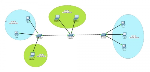
The first switch SW0 is connected to 2 computers PC0 and PC1, which are combined into a VLAN10 network with the IP address range of 192.168.10.0/24. Accordingly, the IP addresses of these computers will be 192.168.10.1 and 192.168.10.2. Generally, people identify the VLAN number by the third octet of the IP address, which in our case is 10. However, this is not a mandatory condition for network designation; you can assign any VLAN identifier, though this practice is common in large companies as it simplifies network configuration.
Next is switch SW1, which is connected to VLAN20 with the IP address of 192.168.20.0/24, with two laptops Laptop1 and Laptop2.
VLAN10 is located on the 1st floor of the company office and represents the network of the sales department's management. This same switch SW0 is connected to the marketing laptop Laptop0, which is part of VLAN20. This network extends to the 2nd floor, where other employees are located, and it connects with the sales department, which may be located in another building or on the 3rd floor of this same office. There are also 3 more computers – PC2, PC3, and PC4, that are part of the VLAN10 network.
The VLAN10 network, like VLAN20, must ensure uninterrupted communication among all employees, regardless of whether they are on different floors or in different buildings. This is the network concept we will review today.
Let's proceed with its configuration starting with computer PC0. By clicking on the icon, we'll enter the network settings of the computer and enter the IP address 192.168.10.1 and the subnet mask 255.255.255.0. I won’t input the default gateway address, as it is needed to exit one local network to another, and in our case, we won’t deal with layer 3 OSI settings; we're only interested in layer 2, and we do not intend to consider routing traffic to another network.
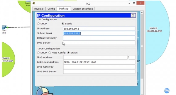
We are going to configure the intranet and only the hosts that are part of it. Then we will move to the PC2 computer and do the same thing as we did for the first PC. Now let's check if I can ping PC1 from the PC0 computer. As you can see, the ping is successful, and the computer with the IP address 192.168.10.2 reliably returns packets. Thus, we have successfully established a connection between PC0 and PC1 through the switch.
To understand why we succeeded, let's go into the switch settings and take a look at the VLAN table.
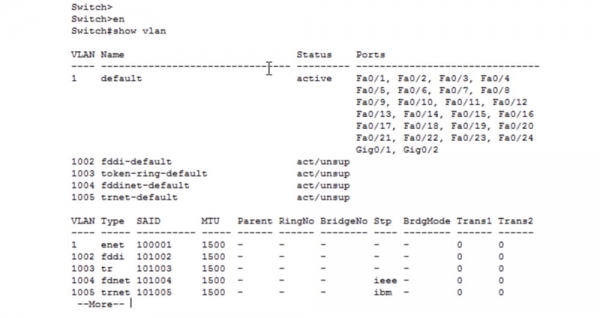
Technically, this switch has 5 VLANs: VLAN1 by default, as well as 1002, 1003, 1004, and 1005. Looking at the last 4 networks, we can see that they are unsupported. These are virtual networks from an old technology – fddi, fddinet, trnet. Currently, they are not in use, but according to technical requirements, they are still included in new devices. Thus, our switch actually has only one virtual network by default – VLAN1, so all ports of any Cisco switch are set to this network 'out of the box'. This includes 24 Fast Ethernet ports and 2 Gigabit Ethernet ports. This significantly simplifies compatibility for new switches because, by default, they are all part of the same VLAN1.
We need to reassign the ports that are by default configured to work with VLAN1 to work with VLAN10. Packet Tracer shows that in our case, these are ports Fa0 and Fa0/2.
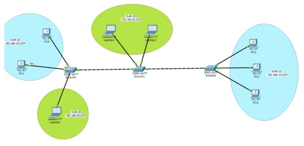
Let's return to switch SW0 and configure these two ports. To do this, I will use the command configure terminal to enter global configuration mode, and I will enter the command to configure this interface – int fastEthernet 0/1. I need to set this port to access mode because this is an access port, and I will use the command switchport mode access.
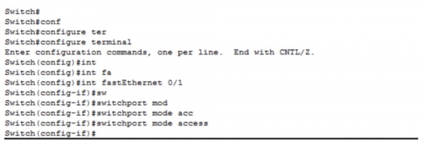
This port is configured as a static access port, but if I connect another switch to it, then thanks to the use of the DTP protocol, it will switch to dynamic trunk mode. By default, this port belongs to VLAN1, so I need to use the command switchport access vlan 10. In this case, the system will prompt us that VLAN10 does not exist and needs to be created. As you may recall, in the VLAN database we have only one network – VLAN1, and there is no network VLAN10 there. But we requested the switch to grant access to VLAN10, so we received an error message.
Therefore, we need to create VLAN10 and assign this access port to it. After that, if we check the VLAN database, we can see the newly created VLAN0010, which is in an active state and to which port Fa0/1 belongs.
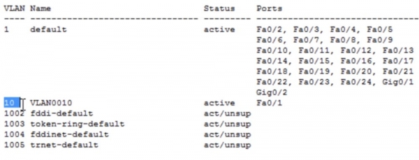
We made no changes to the computer; we simply configured the switch port to which it is connected. Now let's try to ping the IP address 192.168.10.2, which we successfully did a few minutes ago. We had no success because the port to which PC0 is connected now belongs to the VLAN10 network, while the port associated with PC1 still belongs to VLAN1, and there is no connection between these two networks. To establish communication between these computers, both ports must be configured to work with VLAN10. I will again enter global configuration mode and perform similar actions for switchport f0/2.
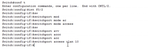
Let's take another look at the VLAN table. Now we see that the VLAN10 network is configured on ports Fa0/1 and Fa0/2. As we can see, the ping is now successful because both switch ports SW0, to which the devices are connected, belong to the same network. Let's try to change the network name to indicate its purpose. If we want to make any changes to the VLAN, we need to go into the configuration for that network.
To do this, I type the command vlan 10, and you can see that the command prompt changed from Switch (config) # to Switch (config-vlan) #. If I type the question mark, the system will show us only 3 possible commands: exit, name, and no. I can assign a name to the network using the name command, revert commands to their default state by typing no, or save the changes by using the exit command. Therefore, I enter the commands name SALES and exit.
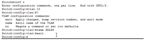
If you look at the VLAN database, you can confirm that our commands have been executed and the former VLAN10 is now named SALES - the sales department. So, we connected 2 computers from our office to the newly created sales department network. Now we need to create a network for the marketing department. To connect the Laptop0 to this network, you need to access its network settings and enter the IP address 192.168.20.1 and subnet mask 255.255.255.0; we do not need a default gateway. Then, return to the switch settings, enter port configuration with the command int fa0/3, and input the command switchport mode access. The next command will be switchport access vlan 20.
We are getting a message again that such a VLAN does not exist and needs to be created. We can take another route – I will exit the switch port settings (config-if), go into Switch (config), and enter the command vlan 20, thereby creating the VLAN20 network. This means we can first create the VLAN20 network, assign it the name MARKETING, save the changes with the command exit, and then configure the port for it.
If you enter the VLAN database command sh vlan, you can see the MARKETING network we created along with its corresponding port Fa0/3. I will not be able to ping the computers from this laptop for two reasons: we have different VLANs and our devices belong to different subnets. Since they belong to different VLANs, the switch will discard packets from the laptop directed to another network because it does not have a port belonging to VLAN20.
As I mentioned, the company is expanding; the small office on the first floor is not enough, so it is placing the marketing department on the 2nd floor of the building, setting up computers for 2 employees there, and wants to ensure communication with the marketing department on the first floor. To do this, we first need to create a trunk between the two switches – from port Fa0/4 of the first switch to port Fa0/1 of the second switch. For this, I enter the SW0 settings and input the commands int f0/4 and switchport mode trunk.
There is an encapsulation command switchport trunk enc; however, it is not applied in new switches because they use encapsulation technology based on protocol 802.1q by default. However, older models of Cisco switches used the proprietary ISL protocol, which is no longer used now since all switches understand the .1Q protocol. Therefore, you no longer need to use the command switchport trunk enc.
If you enter the VLAN database right now, you can see that port Fa0/4 has disappeared. This is because the table only lists access ports that relate to a specific VLAN. To view the trunk ports of the switch, you need to use the command sh int trunk.
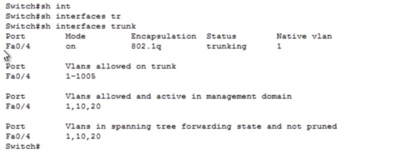
In the command line window, we can see that port Fa0/4 is enabled, encapsulating using the 802.1q protocol and belongs to native VLAN 1. As we know, if this trunk port receives untagged traffic, it automatically directs it to the native VLAN 1 network. In the next lesson, we will discuss configuring the native VLAN; for now, just remember what the trunk settings look like for this device.
Now I am moving to the second switch SW1, entering configuration mode for int f0/1, and repeating the port configuration sequence similar to the previous case. The two ports Fa0/2 and Fa0/3, which are connected to the laptops of the marketing department staff, need to be configured to access mode and assigned to network VLAN20.
In the previous case, we configured each switch port individually, but now I want to show you how to speed up this process using a command line template. You can enter a command to configure a range of interfaces int range f0/2-3, which will change the command prompt to Switch (config-if-range)#, and you can enter the same parameter or apply the same command to the specified range of ports, for example, simultaneously for 20 ports.
In the previous example, we repeatedly used the same commands switchport mode access and switchport access vlan 10 for several switch ports. These commands can be entered once if you use a port range. Now I will enter the commands switchport mode access and switchport access vlan 20 for the selected range of ports.
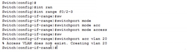
Since network VLAN20 does not exist yet, the system will create it automatically. I type exit to save the changes made and request to show me the VLAN table. As you can see, ports Fa0/2 and Fa0/3 are now part of the newly created VLAN20.
I will now configure the IP addresses for the laptops on the second floor of our office: Laptop1 will be assigned the address 192.168.20.2 with a subnet mask of 255.255.255.0, and Laptop2 will receive the IP address 192.168.20.3. Let's check the network connectivity by pinging the first laptop from the second one. As you can see, the ping is successful because both devices are part of the same VLAN and are connected to the same switch.
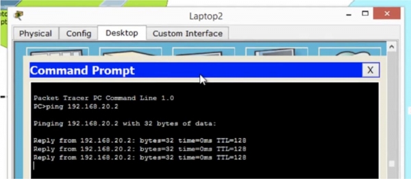
However, the laptops in the marketing department on the first and second floors are connected to different switches, even though they are in the same VLAN network. Let's check how communication is established between them; I will ping the laptop on the first floor with the IP address 192.168.20.1 from Laptop2. As you can see, everything works perfectly despite the fact that the laptops are connected to different switches. Connectivity is achieved because both switches are interconnected via a trunk.
Can I establish a connection between Laptop2 and the PC PC0? No, I cannot because they belong to different VLANs. Now let's set up the network for the computers PC2, PC3, and PC4, for which we will first create a trunk between the second switch Fa0/4 and the third switch Fa0/1.
I enter the settings of SW1 and type the command config t, then I call int f0/4, followed by entering the commands switchport mode trunk and exit. Similarly, I configure the third switch SW2. We have created a trunk, and you can see that after the settings took effect, the colors of the ports changed from orange to green. Now it's necessary to configure ports Fa0/2, Fa0/3, and Fa0/4, which are connected to the sales department computers belonging to VLAN10. For this, I enter the settings of switch SW2, select the range of ports f0/2-4, and apply the commands switchport mode access and switchport access vlan 10. Since VLAN10 is not present on these ports, it is created automatically by the system. If you look at the VLAN database of this switch, you can see that now ports Fa0/2, Fa0/3, and Fa0/4 belong to VLAN10.
After that, it is necessary to configure the network for each of these 3 computers by entering IP addresses and subnet masks. PC2 gets the address 192.168.10.3, PC3 – the address 192.168.10.4, and PC4 – the IP address 192.168.10.5.
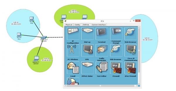
To answer the question of whether our network is working, let's ping the computer PC0 on the first floor from the computer PC4 located on the 3rd floor or in another building. The pinging attempt failed, so let's try to figure out why we couldn't do that.
When we tried to ping Laptop0 from Laptop2, everything worked perfectly, even though the laptops were connected to different switches. So why, now that our sales department computers are also connected to different switches linked by a trunk, is the ping failing? To understand the cause of the problem, we need to recall how a switch operates.
When we send a packet from computer PC4 to switch SW2, it sees that the packet arrives at port Fa0/4. The switch checks its database and discovers that port Fa0/4 belongs to VLAN10. After this, the switch tags the frame with the network number, meaning it attaches the VLAN10 header to the traffic packet and sends it via the trunk to the second switch SW1. This switch 'reads' the header and sees that the packet is intended for VLAN10, looks into its VLAN database, and, finding no VLAN10 there, drops the packet. Thus, devices PC2, 3, and 4 can communicate with each other without issues, but attempts to connect with computers PC0 and PC1 fail because switch SW1 knows nothing about VLAN10.
We can easily fix this problem by going into the settings of SW1, creating VLAN10 using the command vlan 10, and naming it MARKETING. Let's try pinging again – you will see that the first three packets are dropped, while the fourth goes through successfully. This is due to the switch first checking the IP addresses and determining the MAC address, which took some time, causing the first three packets to be dropped due to timeout. Now the connection is established because the switch has updated its MAC address table and directs packets straight to the required address.
All I did to resolve the issue was access the settings of the intermediate switch and create VLAN10 there. Thus, even if the network is not directly connected to the switch, it still needs to be aware of all the networks involved in network connections. However, if your network has a hundred switches, you physically cannot access the settings of each and manually configure VLAN identifiers. This is why we use the VTP protocol, which we will cover in the next video tutorial.
Today, we covered everything we planned: how to create VLANs, how to assign VLAN ports, and how to view the VLAN database. To create networks, we enter the global configuration mode of the switch and use the command vlan , and we can also assign a name to the created network using the command name .

We can also create a VLAN in another way by entering interface mode and using the command switchport access vlan . If there is no network with that number, it will be automatically created by the system. Don't forget to use the exit command after making changes to the initial settings; otherwise, they will not be saved in the VLAN database. You can then assign ports to specific VLAN networks using the appropriate commands.

The command switchport mode access changes the interface to static access-port mode, after which the corresponding VLAN number is assigned to the port using the command switchport access vlan . To view the VLAN database, the command show vlan should be entered in user EXEC mode. To see the list of trunk ports, use the command show int trunk.


Thank you for staying with us. Do you enjoy our articles? Would you like to see more interesting materials? Support us by placing an order or recommending us to your friends. 30% discount for Habr users on a unique entry-level server designed by us for you: (options available with RAID1 and RAID10, up to 24 cores and up to 40GB DDR4).
Dell R730xd for half the price? Only with us in the Netherlands! Dell R420 — 2x E5-2430 2.2GHz 6C 128GB DDR3 2x960GB SSD 1Gbps 100TB — from $99! Read about how
Source: habr.com
