

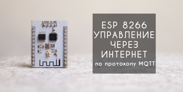
Hello everyone! This article will provide a detailed explanation and demonstration of how to set up remote control of the ESP8266 module using an Android application via the MQTT protocol in just 20 minutes of free time.
The idea of remote control and monitoring has always fascinated those passionate about electronics and programming. The ability to receive or send necessary data at any time, regardless of location, offers vast possibilities. In my previous articles ( and ) I attempted to explore several accessible and relatively simple options for implementing remote control of microcontrollers over the internet. However, time and the world never stand still – progress continues its relentless march forward. In this short time, the ESP8266 module has gained wide popularity thanks to its low cost and built-in Wi-Fi, becoming one of the key components of the “Smart Home.”
Currently, MQTT is the leading and most popular protocol for data transmission between individual devices within “Smart Home” systems. It has several advantages over other protocols:
— low traffic consumption;
— the connection between client and server is always open;
— it does not overload the internet channel;
— no delays in data transmission;
— a convenient subscription system for topics;
All of this allows for real-time monitoring and control. However, MQTT requires its own server, which acts as a mediator between clients on the network. There are two options: either create your own server or use third-party services.
The mentioned management system consists of two main parts: the MQTT server (which is usually one) and clients, which can be quite numerous. In our case, the clients will be the Android application and the ESP8266 module itself.
The system works as follows. Clients connect to the server, and immediately after connecting, each subscribes to their relevant topics. All communication between clients passes transitively through the server, which redirects data to other clients based on their subscriptions.
MQTT server.
In our case, we will use a highly convenient service that has a free tariff plan (Cute Cat), which will fully cover the requirements for implementing a small smart home system.
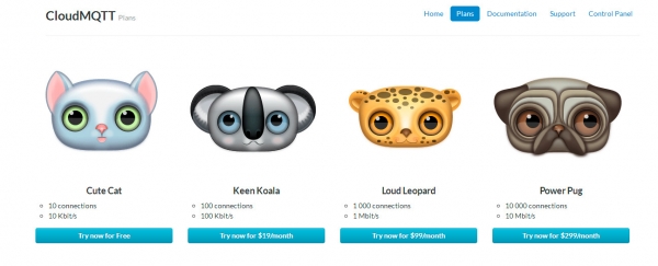
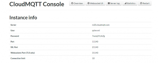
We will register on the website and obtain the necessary data for accessing the server. When configuring clients, you need to use the usual port (without SSL and TLS).
The application on Android.
Our application will act as a remote control for the microcontroller and will also receive and display all information from the esp8266.
The application is called and is a ready-made mqtt client with a small number of very convenient widgets. You can find more details about working with the application in the video.
Esp8266.
The module is programmed in the Arduino programming environment, but I want to note that the module has firmware issues in the latest versions of Arduino, so I recommend using version 1.6.4.
As an example, an LED (pin 5) and a DS18B20 temperature sensor (pin 2) are connected to the esp8266.
Since it is necessary to receive data to control the LED, the esp should subscribe to the corresponding topic "test/led" after connection, otherwise all sent data will bypass our microcontroller.
To send temperature data, subscription is not needed, but when transmitting temperature values, you must specify the topic to which this data will go.
Below is a sketch with detailed comments.
Sketch Esp8266_mqtt.ino// Светодиод подлкючен к 5 пину
// Датчик температуры ds18b20 к 2 пину
#include <ESP8266WiFi.h>
#include <PubSubClient.h>
#include <OneWire.h>
#include <DallasTemperature.h>
#define ONE_WIRE_BUS 2
OneWire oneWire(ONE_WIRE_BUS);
DallasTemperature sensors(&oneWire);
const char *ssid = "AIRPORT"; // Wi-Fi access point name
const char *pass = "PASSWORD"; // Access point password
const char *mqtt_server = "server"; // MQTT server name
const int mqtt_port = 11140; // Port for connecting to the MQTT server
const char *mqtt_user = "Login"; // Server login
const char *mqtt_pass = "Pass"; // Server password
#define BUFFER_SIZE 100
bool LedState = false;
int tm=300;
float temp=0;
// Функция получения данных от сервера
void callback(const MQTT::Publish& pub)
{
Serial.print(pub.topic()); // output the topic name to the serial port
Serial.print(" => ");
Serial.print(pub.payload_string()); // output the received data value to the serial port
String payload = pub.payload_string();
if(String(pub.topic()) == "test/led") // check if the data came from the needed topic
{
int stled = payload.toInt(); // convert the received data to integer type
digitalWrite(5,stled); // turn the LED on or off depending on the received data values
}
}
WiFiClient wclient;
PubSubClient client(wclient, mqtt_server, mqtt_port);
void setup() {
sensors.begin();
Serial.begin(115200);
delay(10);
Serial.println();
Serial.println();
pinMode(5, OUTPUT);
}
void loop() {
// подключаемся к wi-fi
if (WiFi.status() != WL_CONNECTED) {
Serial.print("Connecting to ");
Serial.print(ssid);
Serial.println("...");
WiFi.begin(ssid, pass);
if (WiFi.waitForConnectResult() != WL_CONNECTED)
return;
Serial.println("WiFi connected");
}
// подключаемся к MQTT серверу
if (WiFi.status() == WL_CONNECTED) {
if (!client.connected()) {
Serial.println("Connecting to MQTT server");
if (client.connect(MQTT::Connect("arduinoClient2")
.set_auth(mqtt_user, mqtt_pass))) {
Serial.println("Connected to MQTT server");
client.set_callback(callback);
client.subscribe("test/led"); // subscribing to the topic with data for the LED
} else {
Serial.println("Could not connect to MQTT server");
}
}
if (client.connected()){
client.loop();
TempSend();
}
}
} // end of the main loop
// Функция отправки показаний с термодатчика
void TempSend(){
if (tm==0)
{
sensors.requestTemperatures(); // obtaining temperature value from the sensor
float temp = sensors.getTempCByIndex(0);
client.publish("test/temp",String(temp)); // sending temperature value to the topic for the temperature sensor
Serial.println(temp);
tm = 300; // pause between sending temperature values for about 3 seconds
}
tm--;
delay(10);
}
As a result, we have a convenient tool for remote control and data monitoring, which is quite easy to master and will be accessible even to beginners.
A video demonstrating the operation of the control system
Detailed video instructions for setting up the system
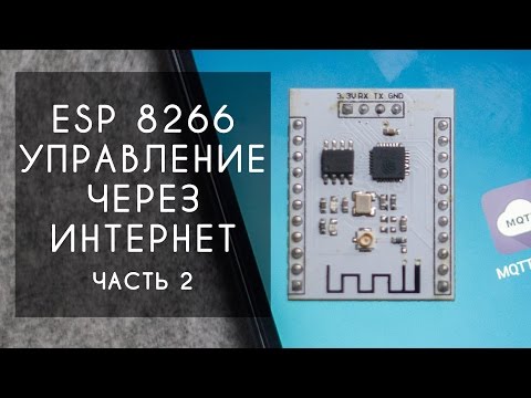
One of the options for controlling the esp8266 via the MQTT protocol
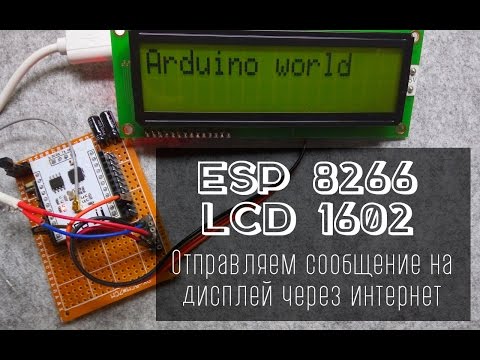
Controlling an LED strip over the internet

If you have any questions about this material, I recommend watching the second part of the video, where the material is presented more visually.
The archive contains the sketch and all necessary libraries for flashing the microcontroller with the example sketch.
Please note that the library ESP8266WiFi.h is not included in this archive, it is installed through the Boards manager in the Arduino environment.
MQTT server —
Link to the IoT MQTT Dashboard application —
Thank you all for your attention.
Source: habr.com
