

Hello, Habr!
After the New Year's holidays, we relaunched the disaster recovery cloud based on two sites. Today, we'll explain how it works and show what happens to client virtual machines in the event of individual cluster component failures and the collapse of an entire site (spoiler - they are just fine).
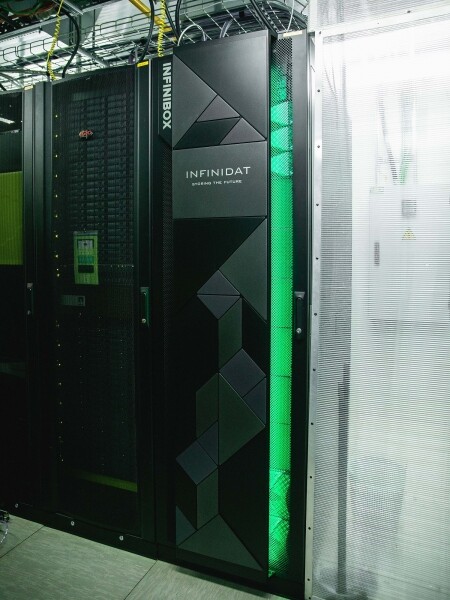
The storage system of the disaster recovery cloud at the OST site.
What's Inside
At the heart of the cluster are Cisco UCS servers with VMware ESXi hypervisor, two INFINIDAT InfiniBox F2240 storage systems, Cisco Nexus network equipment, as well as Brocade SAN switches. The cluster is spread across two sites – OST and NORD, meaning that each data center has the same set of equipment. This is what makes it disaster resilient.
Within a single site, the main elements are also duplicated (hosts, SAN switches, networking).
The two sites are connected by dedicated fiber optic links, which are also redundant.
A few words about the storage systems. The first version of the disaster recovery cloud was built on NetApp. Here, we chose INFINIDAT, and here's why:
- Active-Active replication option. This allows the virtual machine to remain operational even in the event of a complete failure of one storage system. I'll talk about replication in more detail later.
- Three disk controllers to enhance system fault tolerance. Usually, there are two.
- Ready-made solution. We received a pre-assembled rack that just needed to be connected to the network and configured.
- Attentive technical support. INFINIDAT engineers constantly analyze logs and storage system events, install new firmware versions, and assist with configuration.
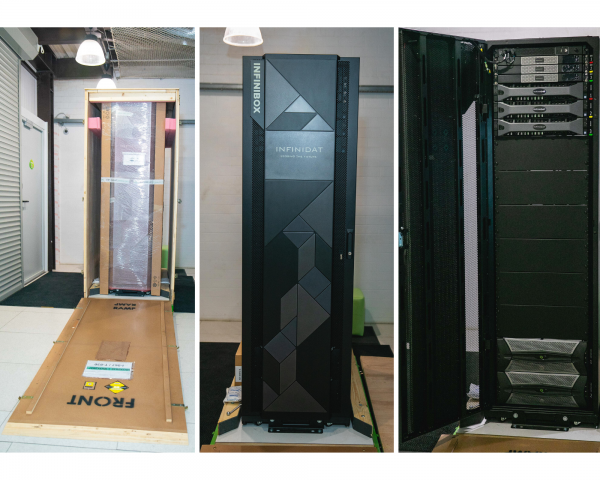
Here are some photos from the unpacking:

How It Works
The cloud is already fault-tolerant in itself. It protects the client from individual hardware and software failures. The disaster recovery aspect helps protect against mass failures within a single site: for instance, storage system (or SDS cluster) failures, widespread errors in the storage network, and more. And most importantly: such a cloud saves when an entire site becomes unavailable due to fire, blackout, hostile takeover, or alien invasions.
In all these cases, client virtual machines continue to operate, and here's why.
The cluster scheme is designed so that any ESXi host with client virtual machines can access either of the two storage systems. If the storage system at the OST site fails, the virtual machines will continue to operate: the hosts on which they run will access data from the storage system at NORD.
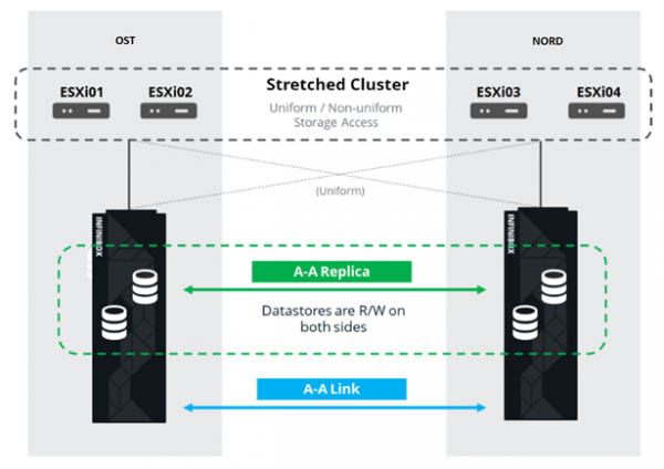
This is what the connection scheme in the cluster looks like.
This is made possible because there is an Inter-Switch Link configured between the SAN fabrics of the two sites: the SAN switch Fabric A OST is connected to the SAN switch Fabric A NORD, and similarly for the SAN switches Fabric B.
To ensure that all these intricate connections of SAN fabrics make sense, an Active-Active replication is configured between the two storage systems: information is written almost simultaneously to the local and remote storage, RPO=0. This means that one storage system holds the original data, while the other holds its replica. Data is replicated at the volume level of the storage systems, and the virtual machine data (its disks, configuration file, swap file, etc.) is stored on them.
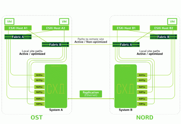
The ESXi host sees the primary volume and its replica as a single storage device. There are 24 paths from the ESXi host to each storage device:
12 paths connect it to the local storage (optimal paths), while the remaining 12 connect to the remote storage (non-optimal paths). In normal situations, ESXi accesses data on the local storage using the 'optimal' paths. If this storage fails, ESXi loses the optimal paths and switches to the 'non-optimal' ones. This is what it looks like in the diagram.
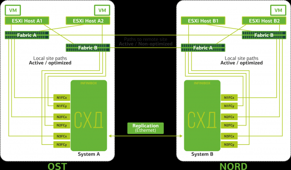
Diagram of a disaster-resistant cluster.
All client networks are routed to both sites through a common network fabric. At each site, a Provider Edge (PE) operates, where client networks are terminated. The PEs are unified into a common cluster. If a PE fails at one site, all traffic is redirected to the second site. As a result, virtual machines from the site that loses the PE remain accessible over the network to the client.
Now let's take a look at what happens to client virtual machines during various failures. We'll start with the mildest scenarios and finish with the most serious one — the failure of an entire site. In these examples, the primary site will be OST, and the backup site, with data replicas, will be NORD.
What happens to the client's virtual machine if…
The Replication Link fails. Replication between the storage systems of the two sites is interrupted.
ESXi will only work with local disk devices (through optimal paths).
The virtual machines continue to operate.
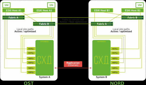
There is an ISL (Inter-Switch Link) interruption. This is an unlikely scenario. Unless a crazy excavator digs up several optical lines that run through independent routes and are brought to sites through different inputs. However, in this case, ESXi hosts will lose half of the paths and can only access their local storage arrays. The replicas will be created, but the hosts will not be able to access them.
The virtual machines are functioning normally.
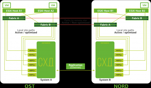
The SAN switch fails at one of the sites. ESXi hosts lose part of the paths to the storage arrays. In this case, hosts at the site where the switch failed will only operate through their single HBA.
The virtual machines continue to operate normally during this.
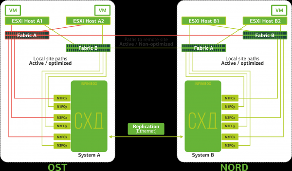
All SAN switches fail at one of the sites. Let's assume such a disaster occurred at the OST site. In this case, ESXi hosts at this site will lose all paths to their disk devices. The standard VMware vSphere HA mechanism comes into play: it will restart all virtual machines at the OST site in NORD within a maximum of 140 seconds.
The virtual machines running on hosts at the NORD site are functioning normally.
An ESXi host fails at one site. In this case, the vSphere HA mechanism kicks in again: the virtual machines from the failed host are restarted on other hosts – at the same site or a remote one. The restart time for a virtual machine is up to 1 minute.
If all ESXi hosts at the OST site fail, there's no other option: the VMs are restarted on another host. The restart time remains the same.
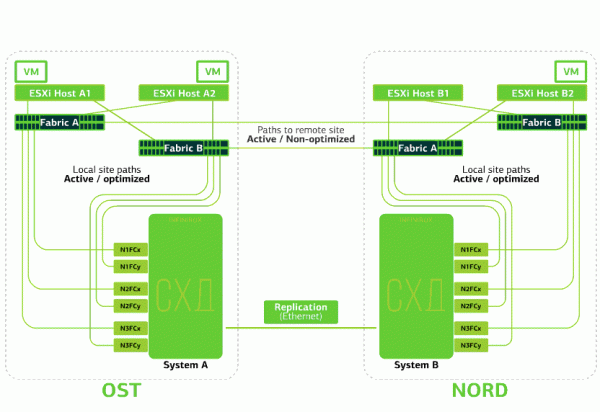
A storage array fails at one site. Let's say the storage array at the OST site has failed. Then, ESXi hosts at the OST site switch to working with storage array replicas in NORD. Once the failed storage array is restored, forced replication will occur, and the ESXi hosts at OST will again access the local storage array.
The virtual machines operate normally during all of this.
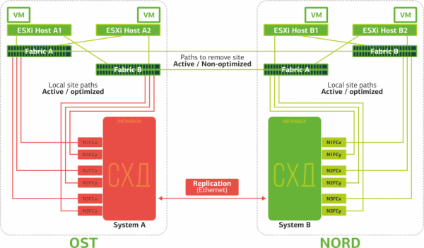
One of the sites fails. In this case, all virtual machines will be restarted at the backup site through the vSphere HA mechanism. The restart time for the VMs is 140 seconds. Additionally, all network settings of the virtual machine will remain intact, and it will remain accessible to the client over the network.
To ensure a smooth restart of machines at the backup site, each site is filled only halfway. The second half serves as a reserve in case all virtual machines need to move from the second, affected site.
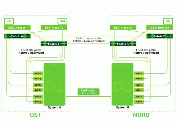
This is what a disaster-resistant cloud based on two data centers protects against.
This comfort does not come cheap, as, in addition to the main resources, a reserve on the second site is required. Therefore, business-critical services are hosted in such a cloud, where prolonged downtime incurs significant financial and reputational losses, or if the information system is subject to disaster resistance requirements from regulators or internal company regulations.
Sources:
Source: habr.com
