

Last time we discussed the features of the new NB-IoT standard from the perspective of radio access network architecture. Today, let's explore the changes that have occurred in the Core Network with NB-IoT. So, let's get started.

Significant changes have taken place in the Core Network. First of all, a new element has been introduced, along with a series of mechanisms defined by the standard as 'CIoT EPS Optimization', or the optimization of the backbone network for cellular IoT.
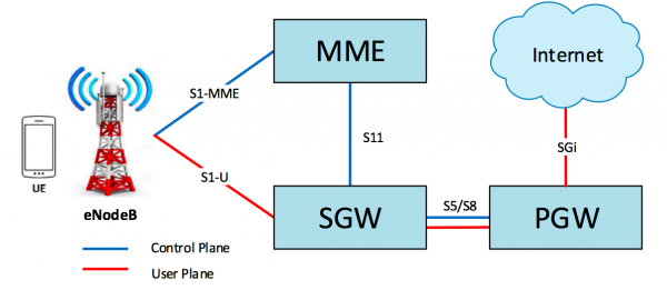
As known, mobile networks have two main communication channels known as the Control Plane (CP) and the User Plane (UP). The Control Plane is intended for the exchange of signaling messages between different network elements and serves to manage the mobility (Mobility management) of devices (UE) and to establish/maintain data session (Session Management). The User Plane is, in fact, the channel for transmitting user traffic. In classical LTE, the distribution of CP and UP across interfaces looks as follows:
The optimization mechanisms for CP and UP in NB-IoT are implemented on the MME, SGW, and PGW nodes, which are conditionally grouped into a single element called the C-SGN (Cellular IoT Serving Gateway Node). The standard also anticipates the introduction of a new network element — SCEF (Service Capability Exposure Function). The interface between MME and SCEF is called T6a and is implemented based on the DIAMETER protocol. Although DIAMETER is a signaling protocol, it is adapted in NB-IoT for transmitting small volumes of non-IP data.
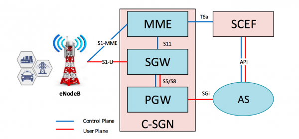
Based on its name, SCEF is a node for exposing service capabilities. In other words, SCEF hides the complexity of the operator's network and relieves application developers from the need to identify and authenticate mobile devices (UE), enabling application servers (Application Server, AS) to retrieve data and manage devices through a unified API interface.
The identifier for UE is no longer the phone number (MSISDN) or IP address, as it was in classic 2G/3G/LTE networks, but rather the so-called 'external ID', which is defined by the standard in a familiar format for application developers: '@'. This is a separate large topic that deserves its own materials, so we won't go into detail about it right now.
Now let's look at the most significant innovations. "CIoT EPS Optimization" is the optimization of traffic transmission and subscriber session management mechanisms. Here are the main ones:
- DoNAS
- NIDD
- Power-saving mechanisms PSM and eDRX
- HLCOM
DoNAS (Data over NAS):
This is a mechanism designed to optimize the transmission of small volumes of data.
In classic LTE, when a subscriber device registers on the network, it establishes a PDN connection (hereafter PDN) through eNodeB to MME-SGW-PGW. The UE-eNodeB-MME connection forms what is known as the “Signaling Radio Bearer” (SRB). When there is a need to transmit/receive data, the UE establishes another connection with the eNodeB — the “Data Radio Bearer” (DRB) — to send user traffic to the SGW and then to the PGW (interfaces S1-U and S5, respectively). After the exchange is complete and in the absence of traffic for a certain period (usually 5-20 seconds), these connections are terminated, and the device enters a waiting mode or “Idle Mode.” When new data needs to be exchanged, the SRB and DRB are re-established.
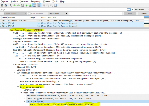
In NB-IoT, user traffic can be transmitted via the signaling channel (SRB) in NAS protocol messages (). Establishment of DRB is no longer required. This significantly reduces signaling load, saves radio resources in the network, and most importantly, extends the device's battery life.
At the eNodeB — MME segment, user data begins to be transmitted over the S1-MME interface, which was not present in classic LTE technology, and a NAS protocol is utilized, which introduces a “User data container.”
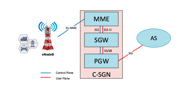
To provide the transmission of “User Plane” from MME to SGW, a new interface S11-U appears, intended for transmitting small volumes of user data. The S11-U protocol is based on GTP-U v1, which is used to transmit User Plane on other interfaces of the 3GPP architecture.
NIDD (non-IP data delivery):
As part of further optimization of small data transmission mechanisms, in addition to the existing PDN types such as IPv4, IPv6, and IPv4v6, another type has emerged — non-IP. In this case, the UE is not assigned an IP address, and data is transmitted without using the IP protocol. There are several reasons for this:
- IoT devices, such as sensors, can transmit very small amounts of data, 20 bytes or even less. Considering that the minimum size of an IP header is 20 bytes, encapsulation in IP can sometimes be quite an expensive endeavor;
- There is no need to implement an IP stack in the chip, which leads to cost reduction (a topic for discussion in the comments).
Basically, an IP address is needed for IoT devices to transmit data over the internet. In the NB-IoT concept, SCEF acts as a single connection point for AS, and data exchange between devices and application servers occurs via API. In the absence of SCEF, non-IP data can be sent to AS through a Point-to-Point (PtP) tunnel from PGW, and the encapsulation in IP will be handled there.
All this fits within the NB-IoT paradigm — maximum simplification and cost reduction of devices.
Power-saving mechanisms PSM and eDRX:
One of the key advantages of LPWAN networks is energy efficiency. It is claimed that a device can operate autonomously on a single battery for up to 10 years. Let's delve into how such figures are achieved.
When does a device consume the least energy? Correct, when it is turned off. And if the device cannot be completely powered down, let's turn off the radio module for the time when it is not needed. However, this must be agreed upon with the network in advance.
PSM (Power Saving Mode):
The Power Saving Mode (PSM) allows the device to turn off the radio module for extended periods while remaining registered with the network, and not having to re-establish the PDN each time it needs to transmit data.
To let the network know that the device is still available, it periodically initiates an update procedure — Tracking Area Update (TAU). The frequency of this procedure is set by the network using the T3412 timer, the value of which is transmitted to the device during the Attach procedure or the subsequent TAU. In classic LTE, the default value for this timer is 54 minutes, and the maximum is 186 minutes. However, to ensure high energy efficiency, needing to access the radio air every 186 minutes is too expensive. To solve this problem, the PSM mechanism was developed.
The device activates PSM mode by in the messages "Attach Request" or "Tracking Area Request" transmitting the values of the two timers T3324 and T3412-Extended. The first determines the time for which the device will be accessible after transitioning to "Idle Mode." The second is the time after which TAU must be performed, and now its value can reach 35,712,000 seconds or 413 days. Depending on the settings, the MME can accept the timer values received from the device or change them by transmitting new values in the messages "Attach Accept" or "Tracking Area Update Accept." Now the device can keep the radio module off for 413 days while remaining registered on the network. As a result, we achieve enormous resource savings for the network and energy efficiency for the devices!
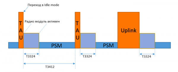
However, in this mode, the device is only unavailable for incoming communications. If it needs to send anything to the application server, the device can exit PSM at any time and send data, remaining active afterward for the timer T3324 to receive informational messages from the AS (if any).
eDRX (extended discontinuous reception):
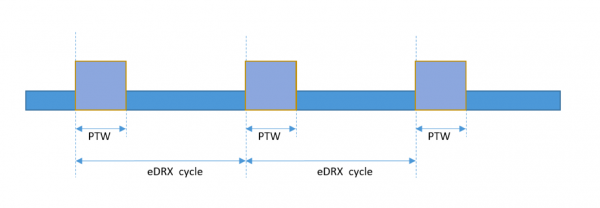
eDRX, the extended discontinuous reception mode. To send data to a device in "Idle mode," the network performs a paging procedure. Upon receiving the paging, the device initiates the establishment of SRB for further communication with the network. However, to not miss the addressed Paging message, the device must constantly monitor the radio channel, which is also quite energy-consuming.
eDRX is a mode where the device receives messages from the network not continuously, but periodically. During the Attach or TAU procedures, the device coordinates with the network the time intervals during which it will "listen" to the air. Accordingly, the Paging procedure will also take place during these same intervals. In eDRX mode, the device's operation is divided into cycles (eDRX cycle). At the beginning of each cycle, there is a so-called "paging window" (Paging Time Window, PTW) — this is the time when the device listens to the radio channel. After PTW ends, the device turns off the radio module until the end of the cycle.
HLCOM (high latency communication):
If necessary to transmit data, the device can exit any of these two power-saving modes without waiting for the end of the PSM or eDRX cycle. However, data can only be transmitted to the device when it is active.
HLCOM functionality or communication with high latencies is the buffering of Downlink packets at the SGW for the time the device is in power-saving mode and unavailable for communication. Buffered packets will be delivered as soon as the device exits PSM, performs a TAU, or transmits Uplink traffic, or when the PTW occurs.
This certainly requires awareness on the part of IoT product developers, as communication with the device is not real-time and requires a specific approach to the construction of business logic for application operation.
In conclusion, we can say that the introduction of new technology is always exciting, and now we are dealing with a standard that has not yet been fully tested even by global giants like Vodafone and Telefonica – making it all the more thrilling. Our presentation of the material does not claim absolute completeness, but we hope it provides a sufficient understanding of the technology. We would appreciate your feedback.
Author: Alexey Lapshin, Expert in Convergent Solutions and Multimedia Services
Source: habr.com
