

Let's once again take a deep dive into the low-level concerns of security for x86-compatible computer platform firmware. This time, the central ingredient of our study is Intel Boot Guard (not to be confused with Intel BIOS Guard!) – a hardware-supported technology for trusted BIOS booting that can be permanently enabled or disabled by the computer system vendor during the manufacturing stage. The method of our inquiry is familiar to us: we will finely slice the reverse engineering of the implementation of this technology, describe its architecture, filling it with undocumented details, season it with attack vectors, and mix it all together. We'll add some heat by discussing how a long-cloned manufacturing error from several vendors allows a potential attacker to exploit this technology to create an undetectable (even by a programmer) hidden rootkit in the system.
By the way, the basis of this article is the reports "Guarding Against Rootkits: Intel BootGuard" from the conference and the 29th meeting of (both presentations ).
Firmware of a computer platform with Intel 64 architecture
To begin, let’s answer the question: what constitutes the firmware of a modern computer platform with Intel 64 architecture? Of course, the UEFI BIOS. However, this answer will not be entirely accurate. Let’s take a look at the diagram depicting the desktop (laptop) variant of this architecture.
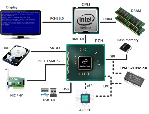
The foundation consists of:
- A CPU (Central Processing Unit), which, in addition to the main cores, integrates a graphics core (not in all models) and an embedded memory controller (IMC);
- A Platform Controller Hub (PCH), containing various controllers for interfacing with peripheral devices and managing subsystems. Among these is the well-known Intel Management Engine (ME), which also has its own firmware (Intel ME firmware).
Laptops, in addition to the above, include an embedded controller (ACPI EC, Advanced Control and Power Interface Embedded Controller), responsible for the functionality of the power subsystem, touchpad, keyboard, Fn keys (screen brightness, sound volume, keyboard backlighting, etc.), and more. It also has its own firmware.
Thus, the combination of the aforementioned firmware constitutes the system firmware, which is stored in the shared SPI flash memory. To prevent users from becoming confused about where each person's data is located, the contents of this memory are divided into the following regions (as shown in the figure):
- UEFI BIOS;
- ACPI EC firmware (a separate region was introduced with the Skylake microarchitecture in 2015, but in the wild, we have not seen examples of its use yet, so the firmware of the embedded controller still falls under UEFI BIOS);
- Intel ME firmware;
- Configuration (MAC address, etc.) of the embedded GbE (Gigabit Ethernet) network adapter;
- Flash Descriptors – the main region of the flash memory that contains pointers to the other regions, as well as access permissions for them.
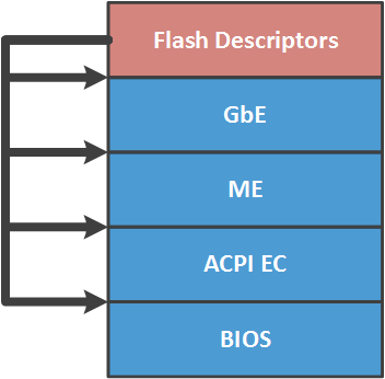
Access control to the regions (according to the specified permissions) is managed by the SPI bus master – an SPI controller built into the chipset, through which access to this memory is executed. If the permissions are set to the recommended values (for security reasons) by Intel, then each user of the SPI flash memory has full access (read/write) only to their region. The others are either read-only or not accessible. It is a known fact: in many systems, the CPU has full access to UEFI BIOS and GbE, read-only access to flash descriptors, and no access at all to the Intel ME region. Why in many, and not all? What is recommended is not mandatory. We will elaborate further in the article.
Mechanisms to protect platform firmware from modification
It is evident that the platform firmware should be protected from potential compromise that would allow a malicious actor to embed themselves within it (surviving OS updates/reinstallations), to execute their code in the most privileged modes, etc. Access restrictions to the SPI flash memory regions alone, of course, are not sufficient. Therefore, various mechanisms specific to each execution environment are used to protect the firmware from modifications.
Thus, the Intel ME firmware is signed to ensure integrity and authenticity, and it is verified by the ME controller each time it is loaded into ME UMA memory. We have already discussed this verification process in one of our , dedicated to the Intel ME subsystem.
The ACPI EC firmware is typically only checked for integrity. However, since this binary is included in the UEFI BIOS, it is almost always subject to the same protection mechanisms as the UEFI BIOS itself. Let’s discuss these.
These mechanisms can be divided into two categories.
Write protection of the UEFI BIOS region
- Physical protection of the SPI flash memory content by a write-protect jumper;
- Protection of the UEFI BIOS region projection in the CPU address space using PRx registers in the chipset;
- Blocking write attempts to the UEFI BIOS region by generating and handling the corresponding SMI interrupt by setting the BIOS_WE/BLE and SMM_BWP bits in the chipset registers;
- A more advanced variant of such protection is Intel BIOS Guard (PFAT).
In addition to these mechanisms, vendors may develop and implement their own security measures (for example, signing capsules with UEFI BIOS updates).
It is important to note that not all of the above-mentioned protection mechanisms may be applied on a specific system (depending on the vendor); some may not be applied at all, or may be implemented in a vulnerable manner. More information about these mechanisms and their implementation can be read in . For those interested, we recommend reviewing the entire series of articles on UEFI BIOS security from .
Verification of UEFI BIOS authenticity
When we talk about trusted boot technologies, the first thing that comes to mind is Secure Boot. However, architecturally it is designed to verify the authenticity of external components (drivers, boot loaders, etc.) in relation to the UEFI BIOS, rather than the firmware itself.
Therefore, Intel implemented a hardware non-disabling Secure Boot (Verified Boot) in SoCs with Bay Trail microarchitecture (2012), which has nothing to do with the aforementioned Secure Boot technology. Later (in 2013), this mechanism was improved and released as Intel Boot Guard for desktops with Haswell microarchitecture.
Before describing Intel Boot Guard, let's discuss the execution environments in the Intel 64 architecture, which, coincidentally, are the roots of trust for this trusted boot technology.
Intel CPU
Cap advises that the processor is the primary execution environment in the Intel 64 architecture. Why is it considered the root of trust? It turns out that it has the following elements:
- Microcode ROM — non-volatile, non-rewritable memory for storing microcode. It is believed that microcode is the implementation of the processor's instruction set in simpler instructions. Bugs also occur in microcode. . Therefore, in the BIOS, one can find binaries with microcode updates (which are applied during boot since ROM cannot be rewritten). The contents of these binaries are encrypted, which significantly complicates analysis (hence, the specific content of the microcode is known only to those who develop it), and signed for integrity and authenticity checks;
- AES key for decrypting the contents of microcode updates;
- the hash of the RSA public key used to verify the signature of microcode updates;
- the hash of the RSA public key used to verify the signature of code modules developed by Intel (Authenticated Code Module, ACM) that the CPU can execute before the BIOS begins execution (hello microcode) or during its operation, triggered by certain events.
Intel ME
This subsystem has been dedicated to in our blog for as long as . Let us remind you that this executable environment is based on a microcontroller embedded in the chipset and is the most hidden and privileged in the system.
Despite its secrecy, Intel ME is also a root of trust, as it has:
- ME ROM — non-volatile, non-rewritable memory (no update method is provided), containing boot code as well as a SHA256 hash of the RSA public key used to verify the signature of the Intel ME firmware;
- AES key for storing secret information;
- access to the integrated chipset set of fuses (FPFs, Field Programmable Fuses) for permanent storage of certain information, including that specified by the system vendor.
Intel Boot Guard 1.x
A small disclaimer. The version numbers of the Intel Boot Guard technology that we use in this article are conditional and may not correspond to the numbering used in Intel's internal documentation. Moreover, the information provided here regarding the implementation of this technology was obtained through reverse engineering and may contain inaccuracies compared to the specification on Intel Boot Guard, which is unlikely to ever be published.
Intel Boot Guard (BG) is a hardware-assisted UEFI BIOS authenticity verification technology. According to its brief description in the book [Platform Embedded Security Technology Revealed, Chapter Boot with Integrity, or Not Boot], it operates as a trusted boot chain. The first link in this chain is the boot code (microcode) inside the CPU, which is activated by a RESET event (not to be confused with the RESET vector in the BIOS!). The CPU locates a code module (Intel BG startup ACM) developed and signed by Intel in the SPI flash memory, loads it into its cache, verifies it (it has already been noted that the CPU possesses the public key hash to check the ACM signature), and initiates execution.
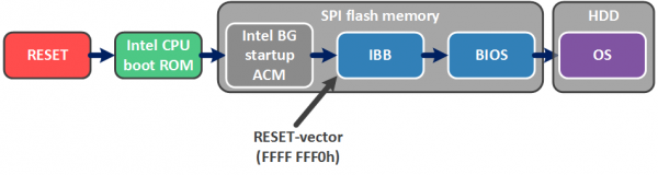
This code module is responsible for verifying a small initial section of the UEFI BIOS — the Initial Boot Block (IBB), which in turn contains functionality for verifying the main part of the UEFI BIOS. Thus, Intel BG ensures the authenticity of the BIOS before loading the operating system (which can operate under the supervision of Secure Boot technology).
The Intel BG technology provides two operational modes (and one does not interfere with the other, meaning both modes can be enabled on the system or both may be disabled).
Measured Boot
In Measured Boot (MB) mode, each boot component (starting from the CPU boot ROM) 'measures' the next one using the capabilities of the TPM (Trusted Platform Module). For those unfamiliar, let us explain.
The TPM contains PCRs (Platform Configuration Registers), where the result of the hashing operation is recorded according to the formula:

That is, the current PCR value depends on the previous one, and the registers are only reset during a system RESET.
Therefore, in MB mode, at a certain point in time, the PCRs reflect a unique (within the capabilities of the hashing operation) identifier of the code or data that has been 'measured'. The PCR values can be used in the encryption of certain data (TPM_Seal). Afterwards, their decryption (TPM_Unseal) will only be possible if the PCR values remain unchanged as a result of the boot (i.e., no 'measured' component has been modified).
Verified Boot
The mode of Verified Boot (VB) is the most alarming for those who enjoy modifying the UEFI BIOS, as each boot component cryptographically checks the integrity and authenticity of the next one. In the event of a verification error, one of the following occurs:
- Timeout shutdown from 1 minute to 30 minutes (to give the user time to understand why their computer isn't booting and, if possible, try to restore the BIOS);
- Immediate shutdown (so the user doesn't have time to understand anything or, even more, do anything);
- Continuing to work with an unflappable attitude (the case when safety is not a priority, as there are more urgent matters).
The choice of action depends on the configured Intel BG setup (specifically, the so-called enforcement policy), which is permanently recorded by the computer platform vendor in a specially designated storage - the chipset fuses (FPFs). We will discuss this point in more detail later.
In addition to the configuration, the vendor generates two RSA 2048 keys and creates two data structures (as shown in the illustration):
- The vendor root key manifest (KEYM, OEM Root Key Manifest), which includes the SVN (Security Version Number) of this manifest, the SHA256 hash of the public key from the next manifest, the RSA public key (i.e., the public part of the vendor root key) for signature verification of this manifest, and the signature itself;
- The IBB manifest (IBBM, Initial Boot Block Manifest), which includes the SVN of this manifest, the SHA256 hash of the IBB, the public key for signature verification of this manifest, and the signature itself.
The SHA256 hash of the OEM Root Key public key is permanently recorded in the chipset fuses (FPFs), just like the Intel BG configuration. If the Intel BG configuration allows for this technology, then from this moment, only the holder of the private part of the OEM Root Key, i.e., the vendor, can update the BIOS (i.e., have the ability to recalculate these manifests) on this system.
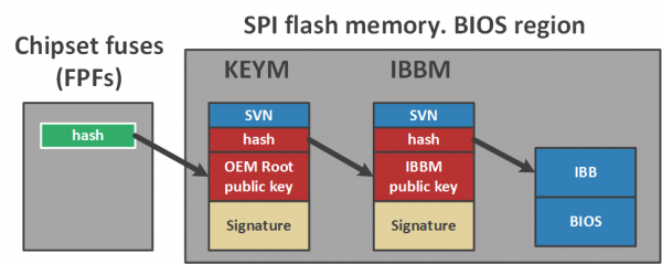
Looking at the picture, one might immediately question the need for such a lengthy verification chain - it could have been simplified to just one manifest. Why complicate things?
In fact, Intel provides the vendor with the opportunity to use different IBB keys for different product lines and one as the root key in this way. If the private part of the IBB key (which is used to sign the second manifest) is leaked, the incident will only affect one product line and only until the vendor generates a new pair and includes the recalculated manifests in the next BIOS update.
However, if the root key (which signs the first manifest) is compromised, it cannot be replaced, as there are no revocation procedures since the hash of the public part of this key is programmed into the FPFs once and for all.
Intel Boot Guard Configuration
Now let's take a closer look at the Intel BG configuration and the process of its creation. If we look at the corresponding tab in the GUI of the Flash Image Tool from the Intel System Tool Kit (STK), we can see that the Intel BG configuration includes the hash of the vendor's root key public part, a couple of unclear values, and the so-called Intel BG profile.
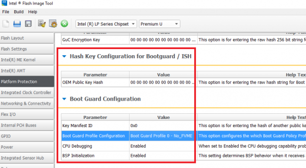
The structure of this profile:
typedef struct BG_PROFILE
{
	unsigned long Force_Boot_Guard_ACM : 1;
	unsigned long Verified_Boot : 1;
	unsigned long Measured_Boot : 1;
	unsigned long Protect_BIOS_Environment : 1;
	unsigned long Enforcement_Policy : 2; // 00b – do nothing
                                              // 01b – shutdown with timeout
                                              // 11b – immediate shutdown
	unsigned long : 26;
};
In general, the Intel BG configuration is a very flexible entity. For example, consider the Force_Boot_Guard_ACM flag. When it is disabled, if the BG startup ACM module is not found in the SPI flash memory, there will be no trusted boot. It will be untrusted.
As mentioned above, the enforcement policy for the VB mode can be set so that in case of a verification error, again, untrusted boot will occur.
Leaving such things to vendors' discretion...
The GUI utility provides the following 'canned' profiles:
Number
Mode
Description
0
No_FVME
Intel BG technology is disabled
1
VE
VB mode is enabled, shutdown after timeout
2
VME
Both modes (VB and MB) are enabled, shutdown after timeout
3
VM
Both modes are enabled, without system shutdown
4
FVE
VB mode is enabled, immediate shutdown
5
FVME
Both modes are enabled, immediate shutdown
As already mentioned, the Intel BG configuration must be permanently written by the system vendor into the chipset fuses (FPFs) – a small (reportedly only 256 bytes) hardware information storage inside the chipset, which can be programmed outside of Intel's manufacturing facilities (hence, specifically Field Programmable Fuses).
It is well-suited for storing configuration because:
- it has a one-time-programmable area for storing data (this is exactly where the Intel BG configuration is written);
- only Intel ME can read and program it.
To configure Intel BG technology on a specific system, the vendor performs the following steps during manufacturing:
- Using the Flash Image Tool (from Intel STK), they create a firmware image with the specified Intel BG configuration as variables within the Intel ME region (the so-called temporary mirror for FPFs);
- Using the Flash Programming Tool (from Intel STK), they write this image to the system's SPI flash memory and close the so-called manufacturing mode (at this point, a corresponding command is sent to Intel ME).
As a result of these operations, Intel ME will commit the specified values from the FPF mirror in the ME region to the FPFs, set the permissions in SPI flash descriptors to the values recommended by Intel (described earlier in the article), and perform a system RESET.
Analysis of Intel Boot Guard Implementation
To analyze the implementation of this technology with a specific example, we checked the following systems for traces of Intel BG technology:
System
Note
Gigabyte GA-H170-D3H
Skylake, supported
Gigabyte GA-Q170-D3H
Skylake, supported
Gigabyte GA-B150-HD3
Skylake, supported
MSI H170A Gaming Pro
Skylake, not supported
Lenovo ThinkPad 460
Skylake, supported, technology enabled
Lenovo Yoga 2 Pro
Haswell, not supported
Lenovo U330p
Haswell, not supported
By 'support', we mean the presence of the Intel BG startup ACM module, the aforementioned manifests, and the corresponding code in the BIOS, i.e., implementation for analysis.
As an example, let’s take the SPI flash memory image downloaded from the vendor's official site for the Gigabyte GA-H170-D3H (version F4).
Intel CPU boot ROM
First, let's talk about the actions of the processor if Intel BG technology is enabled.
Decrypted microcode samples could not be found, so how the actions described below are implemented (in microcode or hardware) remains an open question. Nevertheless, it is a fact that modern Intel processors are capable of performing these actions.
After exiting the RESET state, the processor (whose flash memory contents are already mapped into its address space) finds the FIT (Firmware Interface Table) table. It is easy to find; a pointer to it is recorded at address FFFF FFC0h.
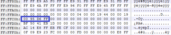
In the example considered, the value FFD6 9500h is located at this address. Upon accessing this address, the processor sees the FIT table, whose contents are divided into records. The first record is the header of the following structure:
typedef struct FIT_HEADER
{
	char Tag[8];     // ‘_FIT_’
	unsigned long NumEntries; // including FIT header entry
	unsigned short Version;    // 1.0
	unsigned char EntryType;  // 0
	unsigned char Checksum;
}; 
For unknown reasons, the checksum is not always calculated in these tables (the field is left null).
The remaining entries point to various binaries that need to be parsed/executed before the BIOS runs, i.e., before transitioning to the legacy RESET vector (FFFF FFF0h). The structure of each such entry is as follows:
typedef struct FIT_ENTRY
{
	unsigned long  BaseAddress;
	unsigned long  : 32;
	unsigned long  Size;
	unsigned short Version;     // 1.0
	unsigned char  EntryType;
	unsigned char  Checksum;
}; 
The EntryType field indicates the type of block that this entry refers to. We know of several types:
enum FIT_ENTRY_TYPES
{
	FIT_HEADER = 0,
	MICROCODE_UPDATE,
	BG_ACM,
	BIOS_INIT = 7,
	TPM_POLICY,
	BIOS_POLICY,
	TXT_POLICY,
	BG_KEYM,
	BG_IBBM
};
It is now clear that one of the entries points to the location of the Intel BG startup ACM binary. The header structure of this binary is typical for the code modules developed by Intel (ACMs, microcode updates, Intel ME code sections, …).
typedef struct BG_ACM_HEADER
{
	unsigned short ModuleType;     // 2
	unsigned short ModuleSubType;  // 3
	unsigned long  HeaderLength;   // in dwords
	unsigned long  : 32;
	unsigned long  : 32;
	unsigned long  ModuleVendor;   // 8086h
	unsigned long  Date;           // in BCD format
	unsigned long  TotalSize;      // in dwords
	unsigned long  unknown1[6];
	unsigned long  EntryPoint;
	unsigned long  unknown2[16];
	unsigned long  RsaKeySize;     // in dwords
	unsigned long  ScratchSize;    // in dwords
	unsigned char  RsaPubMod[256];
	unsigned long  RsaPubExp;
	unsigned char  RsaSig[256];
}; 
The processor loads this binary into its cache, verifies it, and executes it.
Intel BG startup ACM
As a result of analyzing the operation of this ACM, it became clear that it does the following:
- receives the Intel BG configuration from Intel ME, recorded in the chipset fuses (FPFs);
- finds and verifies the KEYM and IBBM manifests.
To find these manifests, the ACM also uses the FIT table, which allocates two types of entries to indicate the structure data (see FIT_ENTRY_TYPES above).
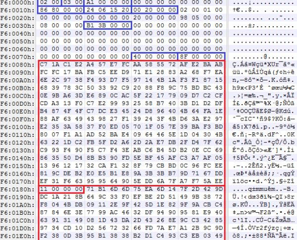
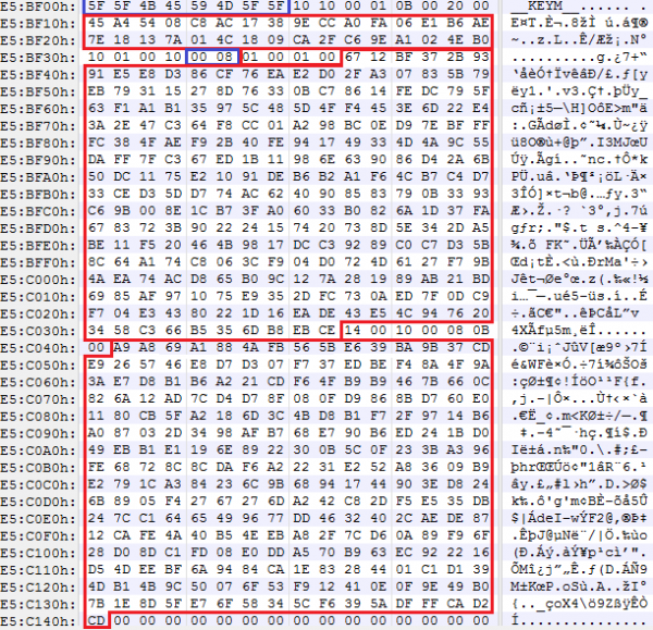
Let's take a closer look at the manifests. In the structure of the first manifest, we see several unclear constants, a hash of the public key from the second manifest, and the OEM Root Key public key with a signature in the form of an embedded structure:
typedef struct KEY_MANIFEST
{
	char           Tag[8];          // '__KEYM__'
	unsigned char  : 8;             // 10h
	unsigned char  : 8;             // 10h
	unsigned char  : 8;             // 0
	unsigned char  : 8;             // 1
	unsigned short : 16;            // 0Bh
	unsigned short : 16;            // 20h == hash size?
	unsigned char  IbbmKeyHash[32]; // SHA256 of an IBBM public key
	BG_RSA_ENTRY   OemRootKey;
};

typedef struct BG_RSA_ENTRY
{
	unsigned char  : 8;             // 10h
	unsigned short : 16;            // 1
	unsigned char  : 8;             // 10h
	unsigned short RsaPubKeySize;   // 800h
	unsigned long  RsaPubExp;
	unsigned char  RsaPubKey[256];
	unsigned short : 16;            // 14
	unsigned char  : 8;             // 10h
	unsigned short RsaSigSize;      // 800h
	unsigned short : 16;            // 0Bh
	unsigned char  RsaSig[256];
}; 
For the verification of the OEM Root Key public key, it is important to note that the SHA256 hash from the fuses, which has already been obtained from Intel ME, is used.
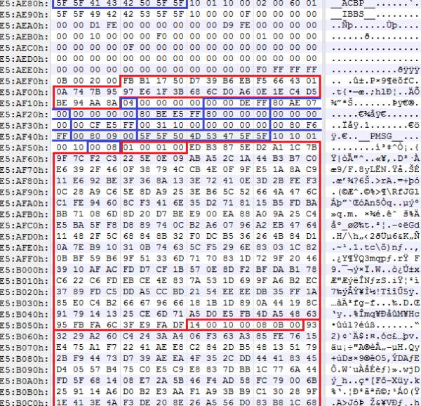
Now let's move on to the second manifest. It consists of three structures:
typedef struct IBB_MANIFEST
{
	ACBP Acbp;         // Boot policies
	IBBS Ibbs;         // IBB description
	IBB_DESCRIPTORS[];
	PMSG Pmsg;         // IBBM signature
};
In the first one, there are some constants:
typedef struct ACBP
{
	char           Tag[8];          // '__ACBP__'
	unsigned char  : 8;             // 10h
	unsigned char  : 8;             // 1
	unsigned char  : 8;             // 10h
	unsigned char  : 8;             // 0
	unsigned short : 16;            // x & F0h = 0
	unsigned short : 16;            // 0 < x <= 400h
};
The second structure contains the SHA256 hash of the IBB and the number of descriptors that describe the contents of the IBB (i.e., the basis for the hash):
typedef struct IBBS
{
	char           Tag[8];            // '__IBBS__'
	unsigned char  : 8;               // 10h
	unsigned char  : 8;               // 0
	unsigned char  : 8;               // 0
	unsigned char  : 8;               // x <= 0Fh
	unsigned long  : 32;              // x & FFFFFFF8h = 0
	unsigned long  Unknown[20];
	unsigned short : 16;              // 0Bh
	unsigned short : 16;              // 20h == hash size ?
	unsigned char  IbbHash[32];       // SHA256 of an IBB
	unsigned char  NumIbbDescriptors;
};
The IBB descriptors follow this structure, one after the other. Their contents have the following format:
typedef struct IBB_DESCRIPTOR
{
	unsigned long  : 32;
	unsigned long  BaseAddress;
	unsigned long  Size;
};
It's straightforward: each descriptor contains the address/size of a piece of the IBB. Thus, the concatenation of the blocks pointed to by these descriptors (in the order of their arrangement) forms the IBB. Generally, the IBB is the aggregate of all modules from the SEC and PEI phases.
The second manifest concludes with a structure containing the public key of the IBB (verified by the SHA256 hash from the first manifest) and the signature of this manifest:
typedef struct PMSG
{
	char           Tag[8];            // '__PMSG__'
	unsigned char  : 8;               // 10h
	BG_RSA_ENTRY   IbbKey;
}; 
Before the execution of the UEFI BIOS begins, the processor will launch the ACM, which will verify the authenticity of the contents of the SEC and PEI code phase sections. Then, the processor exits the ACM, follows the RESET vector, and starts executing the BIOS.
The verified PEI section must contain a module that will check the remainder of the BIOS (DXE code). This module is developed either by the IBV (Independent BIOS Vendor) or by the system vendor itself. Since the systems we have available that support Intel BG are only Lenovo and Gigabyte systems, we will examine the code extracted from these systems.
UEFI BIOS module LenovoVerifiedBootPei
In the case of Lenovo, it turned out to be the LenovoVerifiedBootPei module {B9F2AC77-54C7-4075-B42E-C36325A9468D}, developed by Lenovo.
Its function is to search (by GUID) for the hash table for DXE and verify DXE.
if (EFI_PEI_SERVICES->GetBootMode() != BOOT_ON_S3_RESUME)
{
	if (!FindHashTable())
		return EFI_NOT_FOUND;
	if (!VerifyDxe())
		return EFI_SECURITY_VIOLATION;
}
The hash table {389CC6F2-1EA8-467B-AB8A-78E769AE2A15} has the following format:
typedef struct HASH_TABLE
{
	char          Tag[8];            // ‘$HASHTBL’
	unsigned long NumDxeDescriptors;
	DXE_DESCRIPTORS[];
};
typedef struct DXE_DESCRIPTOR
{
unsigned char BlockHash[32]; // SHA256
unsigned long Offset;
unsigned long Size;
};UEFI BIOS module BootGuardPei
In the case of Gigabyte, it turned out to be the BootGuardPei module {B41956E1-7CA2-42DB-9562-168389F0F066}, developed by AMI, and is hence present in any AMI BIOS that supports Intel BG.
Its algorithm is somewhat different, but ultimately boils down to the same:
int bootMode = EFI_PEI_SERVICES->GetBootMode();

if (bootMode != BOOT_ON_S3_RESUME &&
    bootMode != BOOT_ON_FLASH_UPDATE &&
    bootMode != BOOT_IN_RECOVERY_MODE)
{
	HOB* h = CreateHob();
	if (!FindHashTable())
		return EFI_NOT_FOUND;
	WriteHob(&h, VerifyDxe());
	return h;
}
The hash table {389CC6F2-1EA8-467B-AB8A-78E769AE2A15} that it searches for has the following format:
typedef HASH_TABLE DXE_DESCRIPTORS[];

typedef struct DXE_DESCRIPTOR
{
	unsigned char BlockHash[32];     // SHA256
	unsigned long BaseAddress;
	unsigned long Size;
};
Intel Boot Guard 2.x
Let's briefly discuss another implementation of Intel Boot Guard found in a newer system based on Intel SoC with the Apollo Lake microarchitecture — ASRock J4205-IT.
Although this version will only be applied in SoCs (new systems with Kaby Lake microarchitecture processors continue to use Intel Boot Guard 1.x), it is of significant interest in studying the new architecture variant for Intel SoC platforms, in which there have been notable changes, such as:
- the BIOS regions and Intel ME (or rather Intel TXE, according to the terminology for Intel SoC) are now a single IFWI region;
- Although Intel BG was enabled on the platform, structures such as FIT, KEYM, and IBBM were not found in flash memory;
- In addition to the TXE and ISH cores (x86), a third core (again ARC, by the way) was added to the chipset – PMC (Power Management Controller), associated with ensuring the functionality of the power subsystem and performance monitoring.
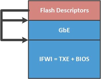
The contents of the new IFWI region consist of the following modules:
Offset
Name
Description
0000 2000h
SMIP
some platform configuration, signed by the vendor
0000 6000h
RBEP
code section of Intel TXE firmware, x86, signed by Intel
0001 0000h
PMCP
code section of Intel PMC firmware, ARC, signed by Intel
0002 0000h
FTPR
code section of Intel TXE firmware, x86, signed by Intel
0007 B000h
UCOD
microcode updates for CPU, signed by Intel
0008 0000h
IBBP
UEFI BIOS, SEC/PEI phases, x86, signed by the vendor
0021 8000h
ISHC
code section of Intel ISH firmware, x86, signed by the vendor
0025 8000h
NFTP
code section of Intel TXE firmware, x86, signed by Intel
0036 1000h
IUNP
unknown
0038 1000h
OBBP
UEFI BIOS, DXE phase, x86, unsigned
During the analysis of the TXE firmware, it became clear that after RESET, TXE keeps the processor in this state until it prepares the basic content of the CPU's address space (FIT, ACM, RESET vector …). TXE places this data in its SRAM, temporarily allows the CPU access to it, and then 'releases' it from RESET.
Guarding against rootkits
Now let's move on to the 'hot' topic. Once, we discovered that in many systems, SPI flash descriptors contained permissions for accessing regions of SPI flash memory such that all users of this memory could read and write any region. i.e., not at all.
After checking with the MEinfo utility (from Intel STK), we saw that manufacturing mode on these systems was not closed, hence the chipset fuses (FPFs) were left in an undefined state. Yes, Intel BG is neither enabled nor disabled in such cases.
We are talking about the following systems (regarding Intel BG and what will be presented further in the article, we will refer to systems with a Haswell microarchitecture and later):
- all Gigabyte products;
- all MSI products;
- 21 models of Lenovo laptops and 4 models of Lenovo servers.
Naturally, we reported our findings to these vendors, as well as to Intel.
A reasonable response was only received from Lenovo, which acknowledged the problem and .
Gigabyte seemingly acknowledged the information about the vulnerability but did not comment further.
Communication with MSI it completely stalled on our request to send their open PGP key (to send them a security advisory in encrypted form). They claimed to be a hardware manufacturer and do not produce PGP keys.
But back to the point. Since the fuses are left in an unspecified state, a user (or attacker) can program them independently (the hardest part is ). The following actions are required to do this.
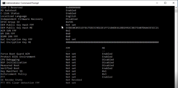
1. Boot into Windows (in fact, the actions described below can also be done from Linux if you develop an analog of Intel STK for the needed OS). Using the MEinfo utility, make sure that the fuses on this system are not programmed.
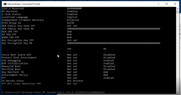
2. Read the contents of the flash memory using the Flash Programming Tool.
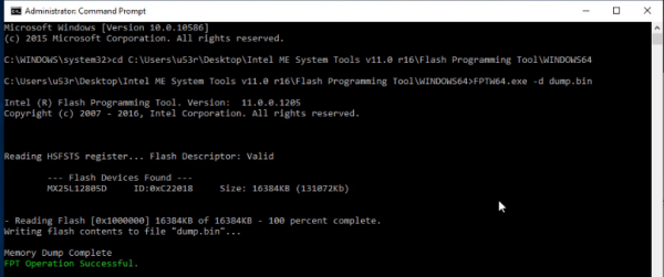
3. Open the read image using any tool for editing UEFI BIOS, make the necessary changes (for example, implant a rootkit), create/edit the existing KEYM and IBBM structures in the ME region.
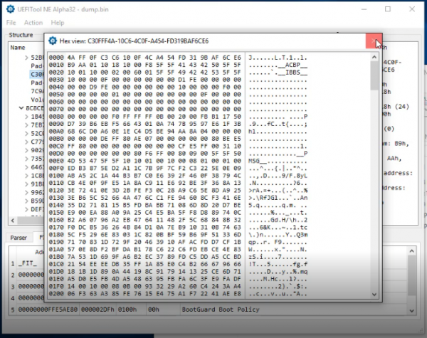
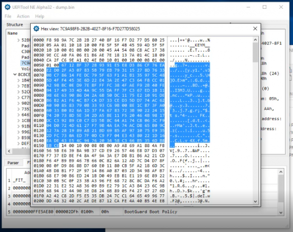
The public part of the RSA key is highlighted in the picture, the hash of which will be programmed into the chipset's fuses along with the rest of the Intel BG configuration.
4. Using the Flash Image Tool, build a new firmware image (setting the Intel BG configuration).
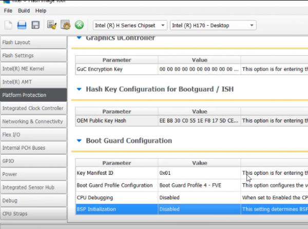
5. Write the new image to the flash memory using the Flash Programming Tool, and use MEinfo to ensure that the ME region now contains the Intel BG configuration.
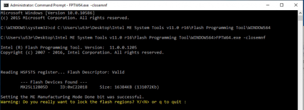
6. Using the Flash Programming Tool, close the manufacturing mode.
7. The system will reboot, after which MEinfo can confirm that the FPFs are now programmed.
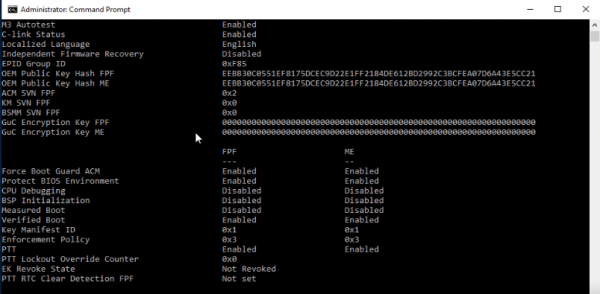
These actions will permanently enable Intel BG on this system. The action cannot be undone, which means:
- the owner of the private part of the root key (i.e., the one who enabled Intel BG) will be the only one able to update the UEFI BIOS on this system;
- if the original firmware is returned to this system, for example, using a programmer, it will not even power on (the result of enforcement policy in the case of a verification error);
- to get rid of such a UEFI BIOS, you need to replace the chipset with one that has unprogrammed FPFs with a 'clean' one (i.e., re-solder the chipset if you have access to an infrared soldering station costing as much as a car, or simply replace the motherboard).
To understand what kind of havoc such a rootkit can wreak, one must assess what it means to execute code in the UEFI BIOS environment. For instance, in the most privileged mode of the processor – SMM. Such a rootkit can possess the following properties:
- it can run concurrently with the OS (configured to trigger via SMI interruption generated by a timer);
- it has all the advantages of operating in SMM mode (full access to RAM and hardware resources, stealth from the OS);
- the rootkit's code can be encrypted and decrypted upon launch in SMM mode. Any data accessible only in SMM can be used as the key for encryption. For example, a hash of a set of addresses in SMRAM. To obtain this key, one would need to access SMM. This can be accomplished in two ways: finding an RCE in the SMM code to exploit, or adding one's own SMM module to the BIOS, which is impossible as Boot Guard has been enabled.
Thus, this vulnerability allows an attacker to:
- create a hidden, undeletable rootkit of unknown purpose in the system;
- execute their code on one of the chipset cores inside the Intel SoC, specifically on the Intel ISH (take a closer look at the image).
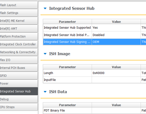
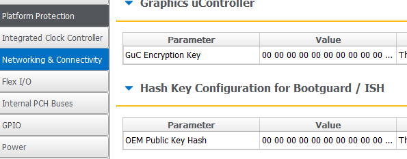
Although the capabilities of the Intel ISH subsystem are not yet fully understood, it appears to be an interesting attack vector for Intel ME.
Conclusions
- The research provided a technical description of how Intel Boot Guard technology works. It sheds light on some of the secrets shrouding Intel's security model of security through obscurity.
- An attack scenario is presented, allowing for the creation of an undeletable rootkit in the system.
- We have observed that modern Intel processors can execute a significant amount of proprietary code even before BIOS initialization.
- Platforms based on Intel 64 architecture are becoming less suitable for running free software: hardware verification, an increasing number of proprietary technologies and subsystems (three cores in the SoC chipset: x86 ME, x86 ISH, and ARC PMC).
Mitigations
Vendors who intentionally leave the manufacturing mode open should definitely close it. So far, they are just turning a blind eye, and the new Kaby Lake systems illustrate this.
Users can disable Intel BG on their systems (which are affected by the described vulnerability) by running the Flash Programming Tool with the -closemnf parameter. First, it is essential to verify (using MEinfo) that the Intel BG configuration in the ME region allows for the disabling of this technology after programming in FPFs.
Source: habr.com
