

In 2019, an unusual storage device, the QUANTUM FIREBALL Plus KA with a capacity of 9.1GB, was delivered to our lab. According to the owner, the failure occurred back in 2004 due to a faulty power supply that also affected the hard drive and other PC components. Subsequent attempts to repair the drive and recover the data at various service centers failed. Some promised low prices without resolving the issue, while others quoted high costs that led the client to decline data recovery. Eventually, the drive went through numerous service centers. At times, it was lost, but because the owner had proactively recorded information from various stickers on the device, he managed to ensure that specifically his hard drive was returned from several service centers. These journeys were not without consequence; the original controller board bore multiple soldering marks, and there was a noticeable lack of SMD components (which, as it turns out, is the least of this drive's problems).
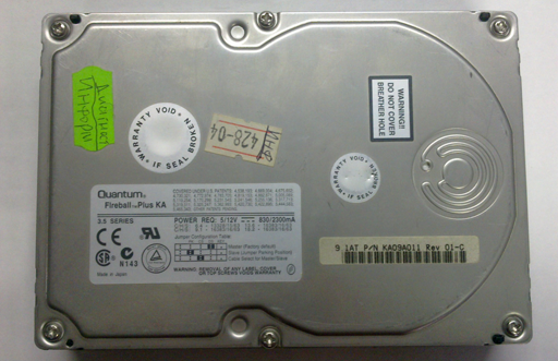
Fig. 1 HDD Quantum Fireball Plus KA 9.1GB
First, it was necessary to search for a donor archive of such an ancient twin of this drive with a functioning controller board. Once this quest was completed, it became possible to conduct extensive diagnostic procedures. After checking the motor windings for short circuits and confirming there were none, we install the donor's board onto the patient drive. Power is supplied, and we hear the normal sound of the spindle spinning up, the calibration test passes with the loading of the firmware, and within a few seconds, the drive reports readiness to respond to commands from the interface.

Fig. 2 The DRD DSC indicators signify readiness to accept commands.
All copies of the firmware modules are reserved. We perform integrity checks on the firmware modules. There are no issues reading the modules, but analysis of the reports reveals some peculiarities.
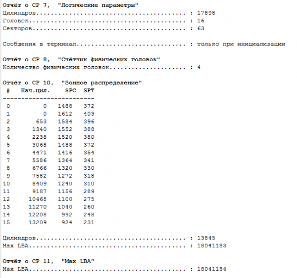
Fig. 3. Zone table.
We focus on the zone distribution table and notice that the number of cylinders is 13845.
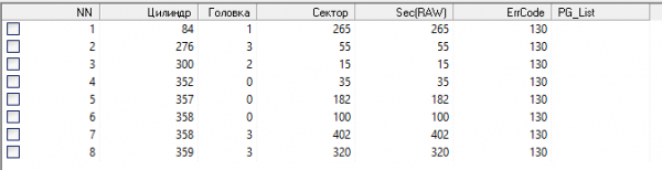
Fig. 4 P-list (primary list – list of defects identified during the production cycle).
We note the very small number of defects and their localization. We review the log module for concealing factory defects (60h) and find that it is empty and contains no entries. Based on this, we can assume that in one of the previous service centers, there might have been some manipulation with the service area of the drive, and either accidentally or intentionally a foreign module was recorded, or the defect list in the original was cleared. To verify this assumption, we create a task in Data Extractor with the options 'create sector-by-sector copy' and 'create virtual translator' enabled.
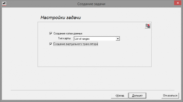
Fig. 5 Task parameters.
After creating the task, we review the entries in the partition table in sector zero (LBA 0).
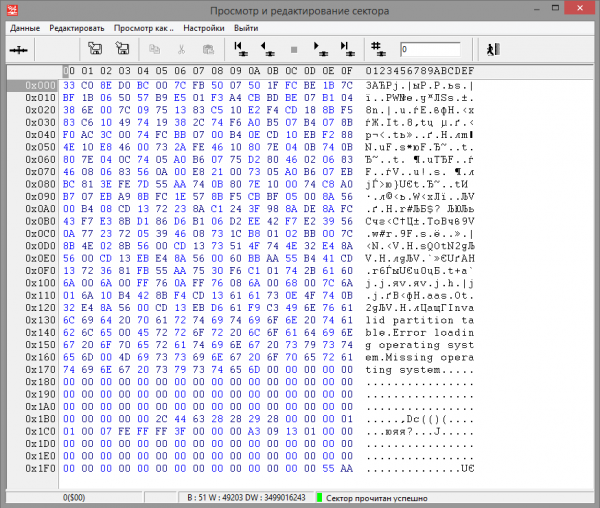
Fig. 6 Master boot record and partition table.
At offset 0x1BE, there is a single entry (16 bytes). The file system type on the partition is NTFS, with an offset to the start of 0x3F (63) sectors, and the partition size is 0x011309A3 (18,024,867) sectors.
In the sector editor, we open LBA 63.
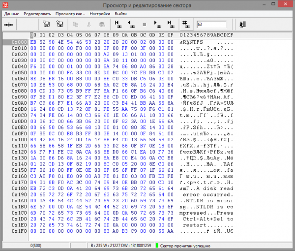
Fig. 7 NTFS boot sector.
From the information in the NTFS boot sector of the partition, we can say the following: the sector size accepted in the volume is 512 bytes (at offset 0x0B the word 0x0200 (512) is recorded), the number of sectors in a cluster is 8 (at offset 0x0D the byte 0x08 is recorded), the cluster size is 512x8=4096 bytes, the first MFT entry is located at an offset of 6,291,519 sectors from the beginning of the disk (at offset 0x30 the quadruple word 0x00 00 00 00 00 0C 00 00 (786,432) is the number of the first MFT cluster. The sector number is calculated by the formula: Cluster number * number of sectors in a cluster + offset to the beginning of the partition 786,432* 8+63= 6,291,519).
We move to sector 6,291,519.
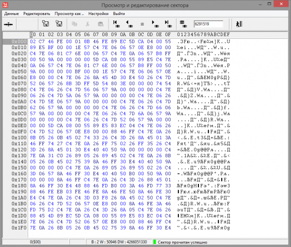
Fig. 8
However, the data contained in this sector does not resemble an MFT entry at all. While this indicates a possible incorrect translation due to an invalid defect list, it does not prove this fact. For further verification, we will read the disk by 10,000 sectors in both directions relative to sector 6,291,519, and then we will conduct a regular expression search on the read data.
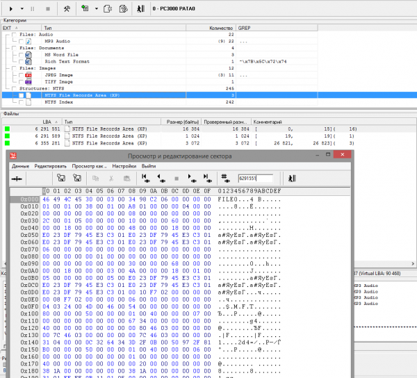
Fig. 9 First MFT entry.
In sector 6,291,551 we find the first MFT entry. Its position differs from the calculated one by 32 sectors, followed by a continuous group of 16 entries (from 0 to 15). We will note the position of sector 6,291,519 shifted forward by 32 sectors in the offsets table.
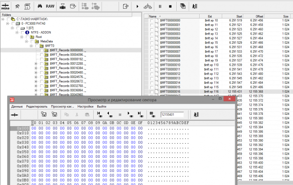
Fig. 10
The position of entry No. 16 should be at offset 12,551,431, but we find zeros instead of the MFT entry. We will conduct a similar search in the vicinity.
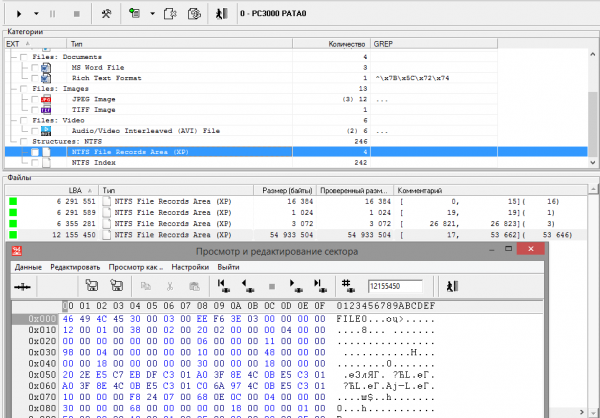
Fig. 11 MFT entry 0x00000011 (17)
A large MFT fragment is identified, starting with entry number 17 spanning 53,646 entries) with an offset of 17 sectors. For position 12,155,431, we will place a shift of +17 sectors in the offset table.
Having determined the position of the MFT fragments in space, we can conclude that this does not resemble a random failure and the recording of MFT fragments with incorrect offsets. The version with an incorrect translator can be considered confirmed.
For further localization of offset points, we will set the maximum possible offset. To do this, we will determine how far the end marker of the NTFS partition has shifted (the copy of the boot sector). In Figure 7, at offset 0x28, the DWORD is the partition size value 0x00 00 00 00 01 13 09 A2 (18,024,866) sectors. Adding the offset of the partition from the start of the disk to its length gives us the offset of the end NTFS marker 18,024,866 + 63 = 18,024,929. As expected, the required copy of the boot sector was not found there. It was discovered in the vicinity with an increasing shift of +12 sectors relative to the last MFT fragment.
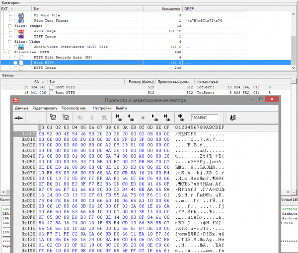
Fig. 12 Copy of the NTFS boot sector
We ignore another copy of the boot sector at offset 18,041,006, as it has no relation to our partition. Based on previous efforts, it has been established that within the partition there are fragments of 'popped up' entries in translation of 61 sectors, which have spread the data.
We perform a complete read of the drive, resulting in 34 unread sectors. Unfortunately, it is not reliably guaranteed that all of them are defects removed from the P-list, but in further analysis, it is advisable to take their position into account, as in some cases it will be possible to reliably determine the offset points with sector precision rather than file precision.
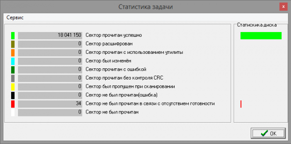
Fig. 13 Disk read statistics.
Our next task will be to establish the approximate shift locations (with precision down to the file in which they occurred). To do this, we will scan all MFT records and create chains of file (and file fragment) locations.
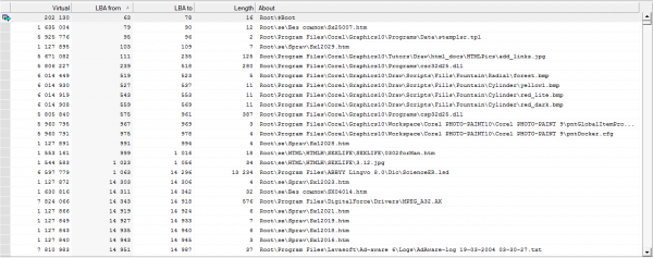
Fig. 14 Chains of file locations or their fragments.
Next, moving from file to file, we look for the point at which other data appears instead of the expected file header, while the necessary header is found with some positive offset. As we refine the shift points, we fill in the table. The result will be over 99% of files intact.
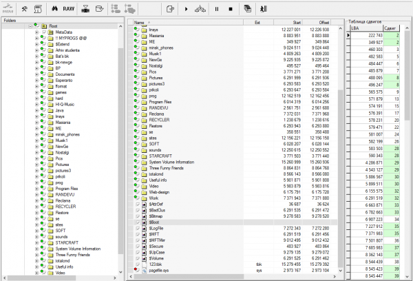
Fig. 15 List of user files (consent was obtained from the client to publish this screenshot)
To establish point shifts in certain files, additional work can be done, and knowing the file structure may help find data fragments not relevant to it. However, for this task, this was not economically feasible.
P.S. I would also like to address colleagues who have handled this disk before. Please be careful when working with device firmware and back up operational data before making any changes, as well as avoid exacerbating the problem if you are unable to come to an agreement with the client about performing the work.
Source: habr.com
