


We established a telephone connection with the guys at SRI… Kleinrock said in an interview:
We typed the L and asked over the phone, "Do you see the L?"
"Yes, we see the L," was the response.
We typed the O and asked, "Do you see the O?"
"Yes, we see the O."
Then we typed the G, and the system crashed…Yet a revolution had begun…
The beginning of the internet.
Hello everyone!
My name is Alexander, I am a network engineer at Linxdatacenter. In today’s article, I will talk about Internet Exchange Points (IXP): what preceded their emergence, the tasks they address, and how they are built. I will also demonstrate how IXP works using the EVE-NG platform and the BIRD software router, so you can understand how it works 'under the hood.'
A Bit of History
If you look , you can notice that the rapid growth of Internet Exchange Points began in 1993. This is related to the fact that most of the traffic of the existing telecommunications operators passed through the backbone network of the USA. For instance, when the traffic was sent from an operator in France to an operator in Germany, it first went to the USA from France and then from the USA to Germany. The backbone network acted as a transit between France and Germany. Even traffic within a single country often did not go directly but rather through the core networks of American operators.
This situation affected not only the cost of delivering transit traffic but also the quality of connections and delays. The number of Internet users was increasing, new operators emerged, and the volume of traffic was rising, causing the Internet to mature. Operators around the world began to understand that a more rational approach to inter-operator interaction was needed. "Why should I, operator A, pay for transit through another country just to deliver traffic to operator B, who is located on the next street?" This is the kind of question telecommunications operators were asking themselves at that time. Thus, in various parts of the world, points of traffic exchange began to appear at operator concentration points:
- 1994 – LINX in London,
- 1995 – DE-CIX in Frankfurt,
- 1995 – MSK-IX in Moscow, etc.
The Internet and our days.
Conceptually, the architecture of the modern internet consists of numerous autonomous systems (autonomous system, AS) and various connections between them, both physical and logical, which determine the path of traffic from one AS to another.
Typically, AS are represented by telecommunications operators, internet service providers, CDNs, data centers, and enterprise segment companies. AS organize logical connections (peering) between themselves, usually through the BGP protocol.
The way autonomous systems organize these connections is determined by several factors:
- geographical,
- economic,
- political,
- agreements and common interests among AS owners,
- etc.
Of course, this scheme has a certain structure and hierarchy. Operators are divided into tier-1, tier-2, and tier-3, and while the clients for a local internet provider (tier-3) are typically regular users, for tier-1 operators, the clients are other operators. Tier-3 operators aggregate the traffic of their subscribers, tier-2 telecom operators aggregate the traffic of tier-3 operators, while tier-1 handles all internet traffic.
This can be represented schematically as follows:
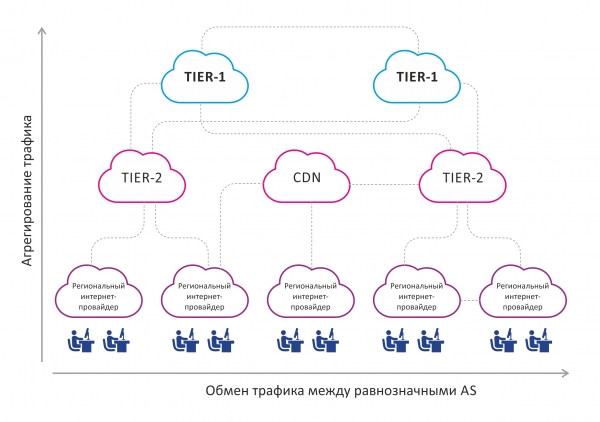
In the image, it can be seen that traffic is aggregated from the bottom up, i.e., from end users to tier-1 operators. There is also a horizontal traffic exchange between AS that are approximately equal in status.
An integral part and at the same time a drawback of this scheme is a certain disorderliness of connections between autonomous systems that are closer to the end user within the geographical area. Let's look at the image below:
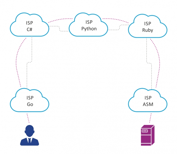
Let's assume that in a large city, there are 5 telecom operators, with peering organized between them for various reasons, as shown above.
If a user named Petya, connected to the internet provider Go, wants to access a server connected to the provider ASM, the traffic between them will have to pass through 5 autonomous systems. This increases the latency, as the number of network devices through which the traffic will pass increases, as does the volume of transit traffic on the autonomous systems between Go and ASM.
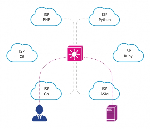
How can we reduce the number of transit AS that traffic has to go through? The answer is a peering point.
The emergence of new IXPs today is driven by the same needs as those in the early 90s to 2000s, but on a smaller scale, in response to the increasing number of telecommunications operators, users, and traffic, as well as the growing volume of content generated by CDN networks and data centers.
What is a traffic exchange point?
A traffic exchange point is a location with specialized network infrastructure where participants interested in mutual traffic exchange establish direct peering relationships. The main participants at traffic exchange points include telecommunications operators, internet service providers, content providers, and data centers. At traffic exchange points, participants connect directly to each other. This addresses the following tasks:
- reduce latency,
- minimize transit traffic,
- optimize routing between AS.
Considering that IXPs are present in many major cities around the world, this has a beneficial effect on the Internet network as a whole.
If we address the situation described above with Petya using IXPs, it would look something like this:
How is a traffic exchange point structured?
Typically, an IXP is a separate AS with its own block of public IPv4/IPv6 addresses.
The IXP network is often represented as a continuous L2 domain. Sometimes, it is simply a VLAN in which all IXP clients are housed. When it comes to larger, geographically distributed IXPs, technologies such as MPLS, VXLAN, etc., may be used to organize the L2 domain.
Elements of an IXP
- Structured Cabling System (SCS). Nothing unusual here: racks, optical cross-connects, patch panels.
- Switches — the foundation of an IXP. The switch port is the entry point into the IXP network. Switches also perform some security functions by filtering out junk traffic that should not be present on the IXP network. Generally, switches are chosen based on functional requirements—reliability, supported port speed, security features, support for sFlow, etc.
- Route server (RS) an integral and necessary part of any modern traffic exchange point. Its operation principle closely resembles that of a route reflector in iBGP or a designated router in OSPF, addressing the same issues. As the number of participants in the traffic exchange point grows, so does the number of BGP sessions that each participant must maintain, resembling a classic full-mesh topology in iBGP. The RS solves this problem by establishing a BGP session with each interested participant of the IXP, which then becomes a client of the RS. Upon receiving a BGP update from one of its clients, the RS redistributes this update to all its other clients, except for the one from which the update was received. In this way, the RS eliminates the need to establish a full-mesh among all IXP participants and elegantly addresses the scalability problem. It is important to note that the route server transparently transmits routes from one AS to another without making changes to the transmitted BGP attributes, such as not adding its own AS number to the AS-path. Additionally, the RS performs basic route filtering: for example, it does not accept martian networks and prefixes of the IXP itself.
As a solution, a software router with open source – BIRD (bird internet routing daemon) is often used as a route server. It is good because it is free, quickly deployable on most Linux distributions, has a flexible policy configuration mechanism for routing/filtering, and is not demanding on computational resources. Also, hardware/virtual routers from Cisco, Juniper, etc., can be selected as RS.
- Security. Since the IXP network is a concentration of a large number of AS, the security policy that all participants must follow should be well defined. Generally, all the same mechanisms used to establish BGP peering between two separate BGP peers outside the IXP are applied here, along with some additional security measures.
For example, a good practice is to allow traffic only from a specific MAC address of the IXP participant, which is agreed upon in advance. Blocking traffic with ethertype fields that differ from 0x0800 (IPv4), 0x08dd (IPv6), 0x0806 (ARP); this is done to filter traffic that has no place in BGP peering. Mechanisms such as GTSM, RPKI, etc., may also be applied.
Undoubtedly, the above components are the main elements of any IXP, regardless of its scale. Of course, larger IXPs may employ additional technologies and solutions.
Sometimes, IXPs also provide their participants with additional services:
- hosting TLD DNS servers at the IXP,
- setting up hardware NTP servers, allowing participants to synchronize time accurately,
- providing DDoS attack protection, etc.
Operating principle
Let's discuss how a traffic exchange point operates using a basic IXP example, modeled using EVE-NG, and then review the basic configuration of the BIRD software router. To simplify the diagram, we will skip important aspects such as redundancy and fault tolerance.
The network topology is illustrated in the figure below.
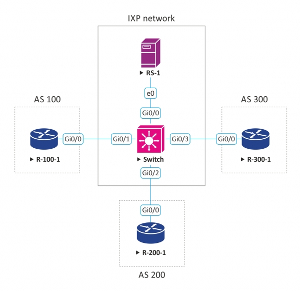
Assuming we are administrating a small traffic exchange point and providing the following peering options:
- public peering,
- private peering,
- peering through a route server.
Our AS number is 555, and we own a block of IPv4 addresses – 50.50.50.0/24, from which we issue IP addresses to those wishing to connect to our network.
50.50.50.254 is the IP address configured on the route server’s interface; with this IP, clients will establish a BGP session when peering through RS.
For peering through RS, we have also developed a simple routing policy based on BGP community, which allows IXP participants to regulate whom and which routes to send:
BGP community
Description
LOCAL_AS:PEER_AS
Send prefixes only to PEER_AS
LOCAL_AS:IXP_AS
Send prefixes to all IXP participants
Our IXP has three clients wishing to connect and exchange traffic; let’s assume they are Internet service providers. All of them wish to set up peering through the route server. Below is a diagram with the connection parameters for the clients:
Client
Client AS number
Prefixes announced by the client
IP address issued to the client for connecting to the IXP
ISP #1
AS 100
1.1.0.0/16
50.50.50.10/24
ISP #2
AS 200
2.2.0.0/16
50.50.50.20/24
ISP #3
AS 300
3.3.0.0/16
50.50.50.30/24
Basic BGP setup on the client router:
router bgp 100
 no bgp enforce-first-as
 bgp log-neighbor-changes
 neighbor 50.50.50.254 remote-as 555
address-family ipv4
  network 1.1.0.0 mask 255.255.0.0
  neighbor 50.50.50.254 activate
  neighbor 50.50.50.254 send-community both
  neighbor 50.50.50.254 soft-reconfiguration inbound
  neighbor 50.50.50.254 route-map ixp-out out
 exit-address-family

ip prefix-list as100-prefixes seq 5 permit 1.1.0.0/16
route-map bgp-out permit 10
 match ip address prefix-list as100-prefixes
 set community 555:555
It is worth noting the setting of no bgp enforce-first-as. By default, BGP requires that the AS number of the BGP peer that sent the update must be present in the AS-path of the received BGP update. However, since the route server does not modify the AS-path, its number will be absent, and the update will be discarded. This setting is applied so that the router begins to ignore this rule.
We also see that the client has set the BGP community 555:555 for this prefix, which according to our policy means that the client wants to announce this prefix to all other participants.
For the routers of other clients, the configuration will be similar, except for their unique parameters.
Example of BIRD configuration:
define ixp_as = 555;
define ixp_prefixes = [ 50.50.50.0/24+ ];

template bgp RS_CLIENT {
  local as ixp_as;
  rs client;
}
Next, a filter is described that does not accept martian prefixes, as well as the IXP prefixes themselves:
function catch_martians_and_ixp()
prefix set martians;
prefix set ixp_prefixes;
{
  martians = [
  0.0.0.0/8+,
  10.0.0.0/8+,
  100.64.0.0/10+,
  127.0.0.0/8+,
  169.254.0.0/16+,
  172.16.0.0/12+,
  192.0.0.0/24+,
  192.0.2.0/24+,
  192.168.0.0/16+,
  198.18.0.0/15+,
  198.51.100.0/24+,
  203.0.113.0/24+,
  224.0.0.0/4+,
  240.0.0.0/4+ ];

  if net ~ martians || net ~ ixp_prefixes then return false;

  return true;
}
This function implements the routing policy that we described earlier.
function bgp_ixp_policy(int peer_as)
{
  if (ixp_as, ixp_as) ~ bgp_community then return true;
  if (ixp_as, peer_as) ~ bgp_community then return true;

  return false;
}

filter reject_martians_and_ixp
{
  if catch_martians_and_ixp() then reject;
  if ( net ~ [0.0.0.0/0{25,32} ] ) then {
    reject;
  }
  accept;


}
We set up peering, applying the corresponding filters and policies.
protocol as_100 from RS_CLIENT {
  neighbor 50.50.50.10 as 100;
  ipv4 {
    export where bgp_ixp_policy(100);
    import filter reject_martians_and_ixp;
  }
}

protocol as_200 from RS_CLIENT {
  neighbor 50.50.50.20 as 200;
  ipv4 {
    export where bgp_ixp_policy(200);
    import filter reject_martians_and_ixp;
  }
}

protocol as_300 from RS_CLIENT {
  neighbor 50.50.50.30 as 300;
  ipv4 {
    export where bgp_ixp_policy(300);
    import filter reject_martians_and_ixp;
  }
}
It is worth noting that on the route server, it is good practice to aggregate routes from different peers into different RIBs. BIRD allows you to do this. In our example, for simplicity, all updates received from all clients are aggregated into one common RIB.
So, let's check what we have achieved.
On the route server, we see that a BGP session is established with all three clients:

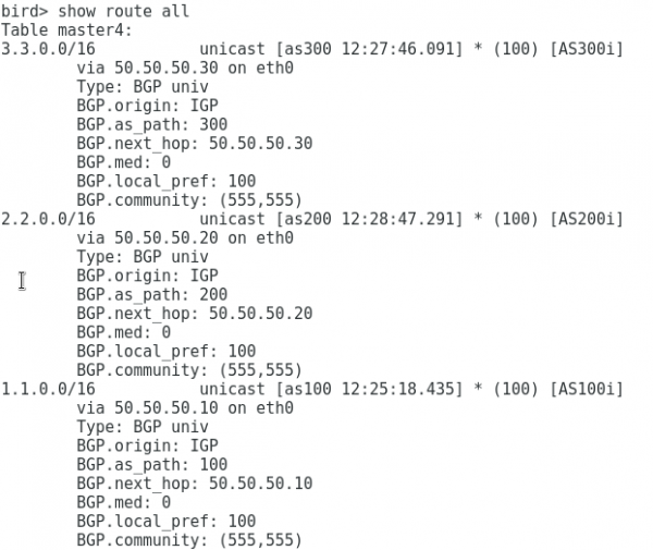
We can see that we are receiving prefixes from all clients:
On the router as 100, we observe that with only one BGP session with the route server, we receive prefixes from both as 200 and as 300, while the BGP attributes remain unchanged, as if the peering between clients were done directly:
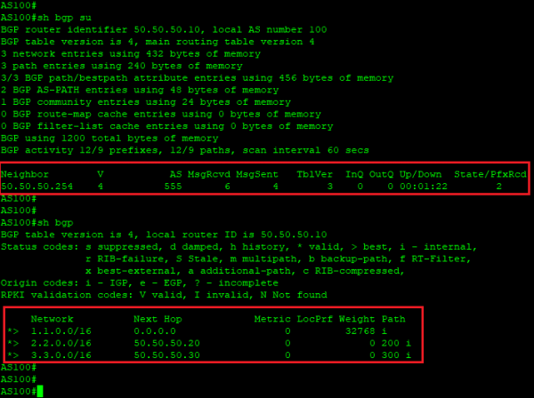
Thus, we see that having a route server significantly simplifies the organization of peering at the IXP.
I hope this demonstration helped you better understand how traffic exchange points work and how the route server operates at the IXP.
Linxdatacenter IX
At Linxdatacenter, we have built our own IXP based on a fault-tolerant infrastructure consisting of 2 switches and 2 route servers. Our IXP is currently in testing mode, and we invite everyone to connect to Linxdatacenter IX and participate in the testing. Upon connection, you will be provided with a port with a capacity of 1 Gbit/s, the ability to peer through our route servers, as well as access to the personal account of the IX portal, available at .
Write in the comments or personal messages to gain access to the testing.
Output
Traffic exchange points arose in the dawn of the internet as a tool to solve the problem of suboptimal traffic flow between telecommunications operators. Now, with the emergence of new global services and the increase in CDN traffic, traffic exchange points continue to optimize the operation of the global network. The increase in the number of IXPs around the world benefits both the end-users of the services and the telecommunications operators, content providers, etc. For IXP participants, benefits include reducing costs for organizing external peerings, decreasing the amount of traffic for which payment must be made to upstream operators, optimizing routing, and the possibility of having a direct connection with content providers.
Useful links
- View the map of traffic exchange points:
- View detailed statistics on BGP peering, including presence at IXP:
Source: habr.com
