

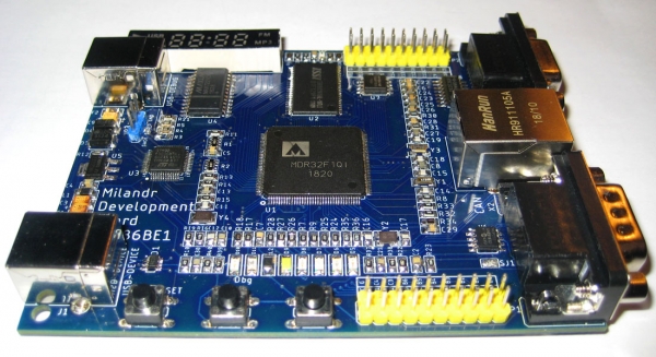
Several years ago, I became acquainted with Russian microcontrollers from Milandr. It was 2013, when engineers were passionately discussing the first results of the federal program for the development of the electronic component base and radio electronics for 2008-2015. At that time, the K1986VE9x controller (Cortex-M3 core) had already been released and the K1986VE1T controller (Cortex-M1 core) was just emerging. It was available in a plastic package LQFP-144 and was documented as K1986VE1QI (aviation), while the chip itself was marked as MDR32F1QI. The manufacturer's website carries the suffix 'aviation' since it features interfaces specific to aerospace applications (ARINC 429, MIL_STD_1553).
Surprisingly, by the time these controllers became available, Milandr had prepared debugging kits and peripheral programming libraries, 'but without any guarantees or obligations regarding the correctness of the library.' The library is similar to the Standard Peripheral Library from STMicroelectronics. In general, all ARM controllers based on the Cortex-M core have much in common. This is why familiarization with the new Russian controllers was rapid. For those who purchased the branded debugging kits, technical support was provided during usage.
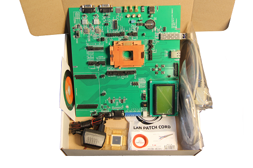
Debugging kit for the microcontroller 1986VE1T, © Milandr
However, over time, the 'growing pains' of the new chips and libraries began to show. Test firmware examples ran without visible issues, but substantial modifications led to crashes and errors. The first 'warning sign' in my experience was unexplained failures in the operation of the CAN controller. After a year, a problem was found with the early revision of the K1986VE1T (aviation) controller's module . In general, all revisions of these microcontrollers up to 2016 had limited usability. A lot of time and nerves were spent identifying these problems, confirmation of which can now be found in .
A frustrating aspect was that I had to work and troubleshoot errors not on debug boards, but on prototype boards of devices that were planned for mass production. Apart from the JTAG connector, there was usually nothing else. Connecting a logic analyzer was difficult and inconvenient, and there were usually no LEDs or screens. For this reason, the idea of creating my own debug board popped into my head.
On one hand, there were branded debug kits on the market, as well as excellent boards from LDM-Systems in Zelenograd. On the other hand, the prices for these products are staggering, and the basic functionality without expansion boards does not meet expectations. A board with a soldered controller and pin connector is not of interest to me. More interesting boards are expensive.
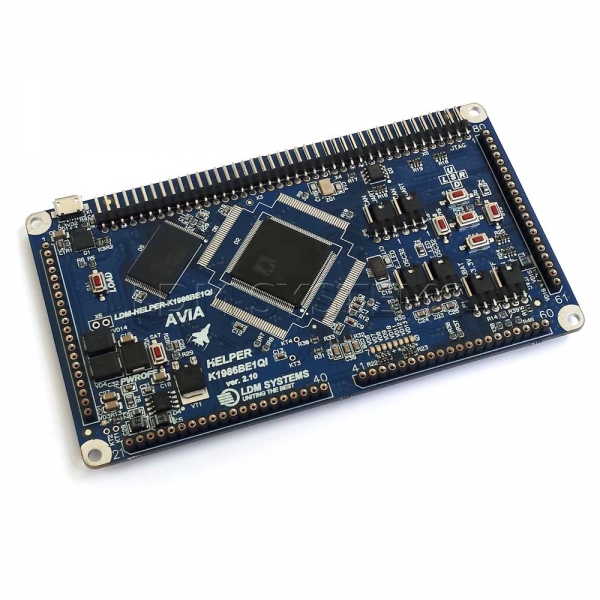
Debug board MILANDR LDM-HELPER-K1986BE1QI-FULL, © LDM Systems
The pricing policy and marketing of the company 'Milandr' are peculiar. For instance, it is possible to obtain free samples of some microchips, but this is only available to legal entities and involves a bureaucratic quest. In general, microchips in metal-ceramic packages are considered 'golden' in both literal and figurative senses. For example, the 1986BE1T controller costs between 14,000 and 24,000 rubles in Moscow. The static memory chip 1645RU6U costs from 15,000 rubles. This pricing is consistent across all products. As a result, even specialized research institutes with government contracts save money and shy away from such prices. Microchips in plastic cases for civilian use are significantly cheaper, but they are not available from popular suppliers. Moreover, the quality of microchips in plastic packaging, in my opinion, is worse than 'golden' ones. For instance, I could not get the K1986BE1QI controller to run at 128MHz without increasing the flash latency parameter. At the same time, the temperature of this controller rose to 40-50°C. In contrast, the 1986BE1T ('golden') controller booted at 128MHz without additional settings and remained cool. It is indeed good.
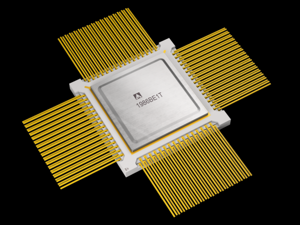
'Golden' microcontroller 1986BE1T, (c) Milandr
I was lucky that the microcontroller in a plastic case is still available for retail purchase from LDM Systems, and all the circuit boards are accessible. The downside is that the website shows a photo of the controller marked as revision 4 from 2014, which means it has defects. I thought long about whether to buy it or not. Years went by...
The thought of creating a debugging board never disappeared. Gradually, I formulated all the requirements and considered how to fit everything onto one board to make it compact and affordable. At the same time, I was ordering the missing components from Chinese suppliers. I was in no hurry—I was doing everything for myself. Chinese suppliers are known for their incompetence—I had to order the same part from different places to get everything I needed. Moreover, some memory chips turned out to be used—clearly desoldered from broken devices. This came back to haunt me later.
Buying the Milandr K1986VE1QI microcontroller (aviation) is not an easy task. In the same store ‘Chip and Dip’ in the ‘Items for Order’ section, I found only K1986BE92QI for 740 rubles, but it wasn't suitable for me. The only option was to buy an outdated revision from LDM-Systems for 2000 rubles. Since I couldn't find a replacement anywhere else, I decided to buy what was available. To my pleasant surprise, I was sold a brand new controller from December 2018, revision 6+ (1820). However, the website still displays the old photo, and at the time of writing, the controller is out of stock...
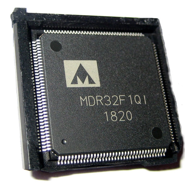
The K1986VE1QI (aviation) microcontroller in a technological package, (c) Photo by the author
Main technical specifications of my debugging board MDB1986 the following:
- built-in debugger-programmer compatible with J-Link and CMSIS-DAP;
- static memory 4Mbit (256k x 16, 10 ns);
- flash memory chip 64Mbit, Winbond 25Q64FVSIG;
- RS-232 interface transceiver with RTS and CTS lines;
- interfaces and connectors for Ethernet, USB, CAN;
- 7-segment display controller MAX7221;
- pin connector for MKIO (MIL_STD_1553) and ARINC429;
- phototransistor Everlight PT17-21C;
- five colored LEDs, a reset button, and two user buttons;
- powered via USB port at 5 volts;
- PCB dimensions 100 x 80 mm
I liked the STM-Discovery series boards for their built-in programmer-debugger – ST-Link. The proprietary ST-Link works only with controllers from STMicroelectronics, but a couple of years ago, it became possible to update the firmware in ST-Link and get the SEGGER J-Link OB (on-board) Debugger. Legally, there is a restriction on using such a debugger only with STMicroelectronics boards, but in practice, the potential is not limited. Thus, having a J-Link OB allows you to have a built-in programmer-debugger on the development board. I would like to note that the LDM-Systems products use the CP2102 (Usb2Uart) converter, which can only be used for programming.
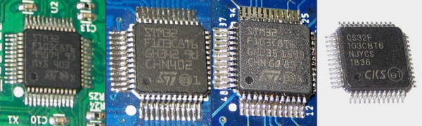
STM32F103C8T6 microcontrollers, both genuine and otherwise, (c) Author's photo
So, I needed to purchase an original STM32F103C8T6, as proprietary firmware would not work correctly with a clone. I was skeptical about this assertion and decided to try out the CS32F103C8T6 controller from the Chinese company CKS. I have no complaints about the controller itself, but the proprietary ST-Link firmware did not work on it. J-Link worked partially – the USB device was recognized, but the programmer did not perform its functions and constantly reminded me that it was ‘defective.’
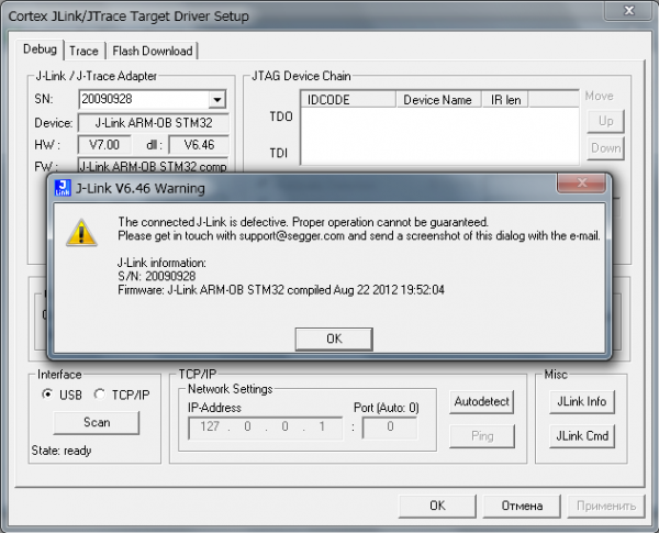
Error when working with the debugger on a non-original controller
I did not stop there and first wrote firmware for blinking an LED, and then implemented the IDCODE request via the JTAG protocol. The ST-Link programmer, which I had on the Discovery board, and the ST-Link Utility program successfully flashed the CS32F103C8T6. In the end, I confirmed that my board works. To my delight, the target controller K1986BE1QI (aviation) boldly issued its IDCODE via the TDO line.
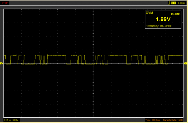
Oscilloscope trace of the TDO signal line with an encoded IDCODE response, (c) Author's photo
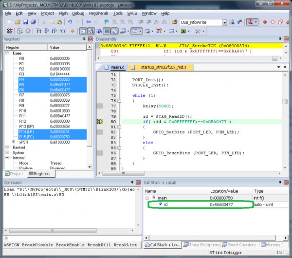
So the SWD port was useful for debugging the debugger itself and checking the IDCODE
There was still the option with the debugger . Assembling a project from source code from ARM is not a simple task; I took a project from , and then I also tried DAP42. Unfortunately, Keil uVision kept freezing and did not want to work with them. In the end, I replaced the debugger chip with the original STM32F103C8T6 and did not come back to this issue.
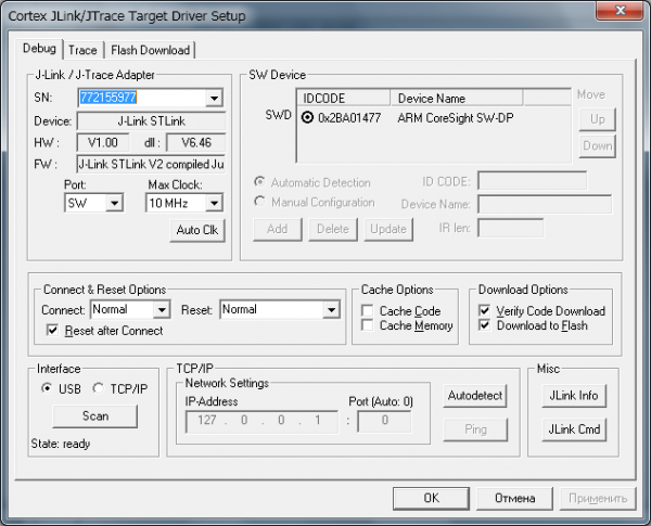
Successful operation of the built-in J-Link STLink V2 debugger
When all the key components of the upcoming debug board were available, I dived into Eagle CAD and found that they were not in the component library. There was no choice—I had to draw them myself. I also created the footprints for the memory, the HanRun connector for Ethernet, and added frames for resistors and capacitors. The project file and component library can be found .
Schematic diagram of the MDB1986 debug board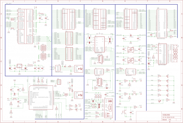
The board is powered by a constant voltage source of 5 volts from a USB port. There are two USB Type-B ports on the board: one for the programmer and the other for the K1986BE1QI controller. The board can operate from either of these sources or both simultaneously. Simple load regulation and power line protection are implemented using Schottky diodes, shown in the schematic as D2 and D3 (SS24). Additionally, you can see self-resetting fuses F1 and F2 rated at 500mA in the schematic. The signal lines of the USB port are protected by the USBLC6-2SC6 diode assembly.
The schematic of the ST-Link debugger/programmer is well-known and can be found in the documentation for STM32-Discovery boards and other sources. For the initial firmware of the ST-Link/J-Link-OB/DAP clone (of your choice), I connected the SWDIO (PA13), SWCLK (PA14), and GND lines. Many use UART for programming and have to fiddle with the BOOT jumpers. However, I find SWD more convenient, plus this protocol allows for debugging.
Almost all components of the board are powered by 3.3 volts, which come from the AMS1117-3.3 voltage regulator. To suppress electromagnetic interference and current spikes, LC filters made from capacitors and BLM31PG series inductors are used.
It is worth mentioning the driver for the 7-segment display MAX7221. According to the specification, the recommended operating voltage is between 4 to 5.5 volts, and the high signal level (logic high) is at least 3.5V (0.7 x VCC) when powered at 5V. For the K1986BE1QI controller (aviation), the logic high output corresponds to a voltage between 2.8 and 3.3V. Clearly, there is a mismatch in signal levels that could disrupt normal operation. I decided to power the MAX7221 from 4V and reduce the signal levels to 2.8V (0.7 x 4 = 2.8). To achieve this, a diode D4 (RS1A or FR103) is placed in series with the power supply of the driver. The total voltage drop is 0.9V (Schottky diode 0.3V and regular diode 0.6V), and it all works.
Most of the ports of the K1986VE1QI microcontroller (aviation) are compatible with signals up to 5V. Therefore, there is no problem using the CAN transceiver MCP2551, which also operates at 5V. The circuit indicates the MAX3232 chip as the RS-232 transceiver, but I actually used the SN65C3232D from Texas Instruments, as it operates at 3.3V and provides speeds up to 1Mbit/s.
The board houses 4 quartz crystal oscillators – one for the debugger (8MHz) and three for the K1986VE1QI microcontroller (aviation) with nominal values of 32.768kHz, 16MHz, and 25MHz. These components are necessary since the parameters of the built-in RC generator vary greatly between 6 and 10 MHz. The 25MHz frequency is required for the built-in Ethernet controller to function. The Milandr website (possibly by mistake) states that the Ethernet is absent in the plastic casing. However, we will rely on the specification and facts.
An important incentive for creating my debugger board was the opportunity to work with an external bus controller (EBC), which is essentially a parallel port. The K1986VE1QI microcontroller (aviation) allows for connecting and working with external memory chips and peripheral devices, such as ADCs, FPGAs, etc. The capabilities of the external system bus are quite extensive – it can work with 8-bit, 16-bit, and 32-bit static RAM, ROM, and NAND Flash. To read/write 32-bit data, the controller can automatically perform 2 corresponding operations for 16-bit chips, and for 8-bit chips, it can execute 4 operations. Clearly, a 32-bit input/output operation will be executed fastest with a 32-bit data bus. A downside is the need for the program to handle 32-bit data, which requires laying out 32 traces on the board.
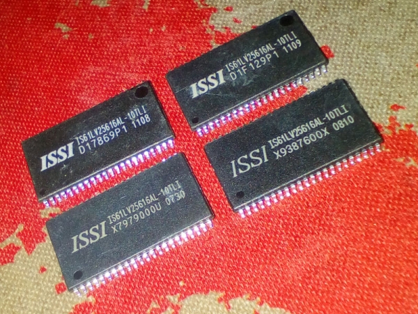
Static RAM chips, used (guess which one has a defect)
A balanced solution is using 16-bit memory chips. I have on hand chips from Integrated Silicon Solutions Inc. (ISSI IS61LV25616AL, 16 x 256k, 10 ns, 3.3V). Of course, Milandr has its own static memory chips. , but they are too expensive and inaccessible. As an alternative, there are compatible Samsung K6R4016V1D chips. I previously mentioned that the chips were used and the one I initially installed caused failures and erratic values in the 15th data line. It took several days to find hardware errors, and it was all the more satisfying when I replaced the damaged chip with a working one. Nevertheless, the speed of working with external memory leaves much to be desired.
External bus and StandAlone modeThe K1986ВЕ1QI (aviation) microcontroller has a unique StandAlone mode designed for direct external access to Ethernet controllers and MKIO (MIL_STD_1553) via the external bus, while the core is in reset state, i.e., not in use. This mode is convenient for processors and FPGAs that lack Ethernet and/or MKIO.
The connection scheme is as follows:
- MCU data bus (D0-D15) => SRAM (I/O0-I/O15),
- MCU address bus (A1-A18) => SRAM (A0-A17),
- MCU control (nWR, nRD, PortC2) => SRAM (WE, OE, CE),
- SRAM (UB, LB) is connected or pulled to ground through a resistor.
The CE line is pulled to power through a resistor, the byte selection outputs of the MCU (BE0-BE3) are not used. Under the spoiler, I provide the initialization code for the ports and the external bus controller.
Initialization of ports and the EBC (external bus controller)
void SRAM_Init (void)
{
	EBC_InitTypeDef          EBC_InitStruct = { 0 };
	EBC_MemRegionInitTypeDef EBC_MemRegionInitStruct = { 0 };
	PORT_InitTypeDef         initStruct = { 0 };

	RST_CLK_PCLKcmd (RST_CLK_PCLK_EBC, ENABLE);

	PORT_StructInit (&initStruct);
	//--------------------------------------------//
	// DATA PA0..PA15 (D0..D15)                   //
	//--------------------------------------------//
	initStruct.PORT_MODE      = PORT_MODE_DIGITAL;
	initStruct.PORT_PD_SHM    = PORT_PD_SHM_ON;
	initStruct.PORT_SPEED     = PORT_SPEED_FAST;
	initStruct.PORT_FUNC      = PORT_FUNC_MAIN;
	initStruct.PORT_Pin       = PORT_Pin_All;
	PORT_Init (MDR_PORTA, &initStruct);
	//--------------------------------------------//
	// Address PF3-PF15 (A0..A12), A0 - not used. //
	//--------------------------------------------//
	initStruct.PORT_FUNC      = PORT_FUNC_ALTER;
	initStruct.PORT_Pin       = PORT_Pin_4  | PORT_Pin_5  |
	                            PORT_Pin_6  | PORT_Pin_7  |
	                            PORT_Pin_8  | PORT_Pin_9  |
								PORT_Pin_10 | PORT_Pin_11 |
	                            PORT_Pin_12 | PORT_Pin_13 |
								PORT_Pin_14 | PORT_Pin_15;
	PORT_Init (MDR_PORTF, &initStruct);
	//--------------------------------------------//
	// Address PD3..PD0 (A13..A16)                //
	//--------------------------------------------//
	initStruct.PORT_FUNC      = PORT_FUNC_OVERRID;
	initStruct.PORT_Pin       = PORT_Pin_0 | PORT_Pin_1 |
	                            PORT_Pin_2 | PORT_Pin_3;
	PORT_Init (MDR_PORTD, &initStruct);
	//--------------------------------------------//
	// Address PE3, PE4 (A17, A18)                //
	//--------------------------------------------//
	initStruct.PORT_FUNC      = PORT_FUNC_ALTER;
	initStruct.PORT_Pin       = PORT_Pin_3 | PORT_Pin_4;
	PORT_Init (MDR_PORTE, &initStruct);
	//--------------------------------------------//
	// Control PC0,PC1 (nWE,nOE)                  //
	//--------------------------------------------//
	initStruct.PORT_FUNC      = PORT_FUNC_MAIN;
	initStruct.PORT_Pin       = PORT_Pin_0 | PORT_Pin_1;
	PORT_Init (MDR_PORTC, &initStruct);
	//--------------------------------------------//
	// Control PC2 (nCE)                          //
	//--------------------------------------------//
	initStruct.PORT_PD        = PORT_PD_DRIVER;
	initStruct.PORT_OE        = PORT_OE_OUT;
	initStruct.PORT_FUNC      = PORT_FUNC_PORT;
	initStruct.PORT_Pin       = MDB_SRAM_CE;
	PORT_Init (MDR_PORTC, &initStruct);

	//--------------------------------------------//
	// Initialize EBC controller                   //
	//--------------------------------------------//
	EBC_DeInit();
	EBC_StructInit(&EBC_InitStruct);
	EBC_InitStruct.EBC_Mode             = EBC_MODE_RAM;
	EBC_InitStruct.EBC_WaitState        = EBC_WAIT_STATE_3HCLK;
	EBC_InitStruct.EBC_DataAlignment    = EBC_EBC_DATA_ALIGNMENT_16;
	EBC_Init(&EBC_InitStruct);

	EBC_MemRegionStructInit(&EBC_MemRegionInitStruct);
	EBC_MemRegionInitStruct.WS_Active   = 2;
	EBC_MemRegionInitStruct.WS_Setup    = EBC_WS_SETUP_CYCLE_1HCLK;
	EBC_MemRegionInitStruct.WS_Hold     = EBC_WS_HOLD_CYCLE_1HCLK;
	EBC_MemRegionInitStruct.Enable_Tune = ENABLE;
	EBC_MemRegionInit (&EBC_MemRegionInitStruct, EBC_MEM_REGION_60000000);
	EBC_MemRegionCMD(EBC_MEM_REGION_60000000, ENABLE);

	// Turn ON RAM (nCE)
	PORT_ResetBits (MDR_PORTC, MDB_SRAM_CE);
}
The microcontroller in an LQFP-144 package and memory in a TSOP-44 package have many related pins and occupy a lot of space on the printed circuit board. With my experience in solving optimization tasks in the field of economics, it was clear to me that these chips needed to be placed on the board first. I had come across praise for different sources. . I downloaded the trial version and was able to export my project from Eagle CAD only after removing almost all components. Unfortunately, even 10 components, the TopoR program did not help me place on the board. Initially, all components were placed in the corner, and then arranged along the edge. This option did not satisfy me, and I spent a long time routing the board manually in the familiar Eagle CAD environment.
An important element of the printed circuit board is silkscreen. The debugging board should have not only labels for the electronic components, but all connectors should also be labeled. On the back of the board, I placed reminder tables with the functions of the controller ports (main, alternative, overridden, actual). I ordered the manufacturing of the printed circuit boards in China from the well-known company PCBWay. I won't praise them too much because the quality is good. They could make it better, with tighter tolerances, but .
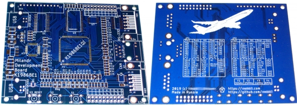
The manufactured printed circuit boards MDB1986, (c) Author's photo
I had to solder the components 'on the fly' with a 40-watt soldering iron and POS-61 solder, because I rarely solder, 1-2 times a year, and the solder paste dried up. I also had to replace the Chinese controller CS32F103 with the original STM32F103, and then also replace the memory. Overall, I am fully satisfied with the result now, although I have not yet checked the operation of RS-232 and CAN.
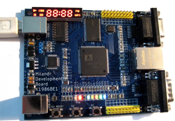
The debugging board MDB1986 in operation — lights up and heats, (c) Author's photo
On the Milandra website, you can find enough the 1986BE9 series (Cortex-M3 core), but I don't see anything for the K1986BE1QI (aviation) microcontroller. Reviewing the published materials, guidelines, and laboratory works for universities, I'm pleased that training is being conducted across the country to work with Russian controllers. Most educational materials prepare for working with input-output ports, timers, ADCs, DACs, SPI, UART. Different IDE development environments are used (Keil, IAR, CodeMaster). Some program using the CMSIS registers, while others use the MDR Library. It is necessary to mention the resource , which contains many articles from practicing programmers. And, of course, we must not forget about the .
Milandr's HouseMicroelectronics in Russia is developing, and in this process, the company 'Milandr' plays a significant role. New interesting microcontrollers are emerging, such as the 1986BE81T and 'Electrosila' with SpaceWire and MKIO interfaces (similar to those in the 1986BE1 and possibly with the same issues), etc. However, it is almost impossible for ordinary students, teachers, and civil engineers to purchase such chips. This means that the engineering community will not be able to quickly identify errors and problems with this microchip. I think we first need to release chips in a plastic package, distribute them among all interested parties, and only after testing (Latin approbatio - approval, recognition) by specialists can we prepare a revision in a ceramic package with protections against all dreadful factors. I hope that in the near future we will all be pleased with the new projects showcased at exhibitions.
Anyone can replicate, modify, and use the debugging board I developed in the educational process. Primarily, I made the board for myself, but it turned out so well that .
K1986BE1QI (aviation) is a very interesting controller with unique interfaces that can be used in universities for training students. I believe that after correcting the identified errors in the controller and passing certification tests, the controller will literally take off!
Source: habr.com
