

Readers are invited to familiarize themselves with the principles of building a resilient infrastructure for a small enterprise within a single data center, which will be detailed in a short series of articles.
Introduction
Under data center (Data Center) can be understood as:
- a dedicated rack in its own "server room" on the enterprise's premises, meeting minimum requirements for power supply and cooling systems, and having an Internet connection via two independent providers;
- a rented rack with the enterprise's own equipment, located in a genuine data center – known as colocation, which complies with Tier III or IV standards and guarantees reliable power supply, cooling, and a failover Internet connection;
- fully rented equipment in a Tier III or IV data center.
Which placement option to choose – in each case, it is entirely individual and usually depends on several key factors:
- the purpose of having an IT infrastructure at all;
- what the enterprise specifically expects from the IT infrastructure (reliability, scalability, manageability, etc.);
- the amount of initial investment in the IT infrastructure, as well as the type of expenses for it – capital (which means purchasing its own equipment) or operational (typically renting equipment);
- the planning horizon of the enterprise itself.
There is much to say about the factors influencing the enterprise's decision on creating and using its IT infrastructure, but our goal is to practically demonstrate how to build this very infrastructure such that it is resilient and also allows for cost savings – reducing expenses on commercial software acquisition or even avoiding them altogether.
Long experience shows that saving on hardware is unwise, as a penny pincher pays twice as much, if not more. However, good hardware is merely a recommendation, and ultimately what to purchase and at what cost depends on the company's capabilities and the 'thriftiness' of its management. The term 'thriftiness' should be understood in a positive light, as investing in hardware at the initial stage is preferable to facing serious issues with its ongoing support and scalability later on. Poor planning and excessive frugality can lead to far greater expenses in the future than anticipated when launching a project.
So, the initial data for the project is as follows:
- there is a company that has decided to create its own web portal and bring its activities online;
- the company has decided to rent a rack to host its equipment in a reputable data center, certified to the Tier III standard;
- the company has decided not to skimp on hardware, and thus purchased the following equipment with extended warranties and support:
Equipment List
- two physical Dell PowerEdge R640 servers with the following specifications:
- two Intel Xeon Gold 5120 processors
- 512 GB of RAM
- two SAS disks in RAID1 for the OS installation
- built-in 4-port 1G network interface card
- two 2-port 10G network interface cards
- one 2-port 16G FC HBA.
- A dual-controller Dell MD3820f storage system, connected via 16G FC directly to the Dell hosts;
- two layer 2 switches — Cisco WS-C2960RX-48FPS-L, combined into a stack;
- two layer 3 switches — Cisco WS-C3850-24T-E, combined into a stack;
- Rack, UPS, PDU, console servers — provided by the data center.
As we can see, the existing hardware has good prospects for horizontal and vertical scaling, should the company be able to compete with other similar firms online and begin generating profit that can be reinvested in expanding resources for further competition and profit growth.
What additional equipment can we add if the company decides to increase the performance of our computing cluster:
- we have ample spare ports on the 2960X switches, meaning we can add more hardware servers;
- purchase two FC switches to connect them to the storage system and additional servers;
- existing servers can be upgraded – add memory, replace processors with more powerful ones, connect to a 10G network using existing network adapters;
- additional disk shelves with the necessary disk types – SAS, SATA or SSD, depending on the planned load, can be added to the storage system;
- after adding FC switches, another storage system can be purchased to increase disk capacity, and if a special Remote Replication option is added, data replication between storage systems can be set up both within a single data center and between data centers (but this is beyond the scope of this article);
- there are also Layer 3 switches – Cisco 3850, which can be utilized as a fault-tolerant core of the network for high-speed routing between internal networks. This will be very helpful as the internal infrastructure grows. Additionally, the 3850 has 10G ports that can be utilized later when upgrading network equipment to 10G speeds.
Since virtualization is now indispensable, we will of course be on trend, especially since it is an excellent way to reduce expenses for purchasing expensive servers for individual infrastructure components (web servers, databases, etc.), which are not always optimally used in case of low load, as will be the case at the beginning of the project's launch.
Moreover, virtualization has many other advantages that will be very useful to us: VM fault tolerance in case of hardware server failure, Live migration between hardware nodes of the cluster for maintenance, manual or automatic load balancing among cluster nodes, etc.
For hardware purchased by the enterprise, the deployment of a highly available VMware vSphere cluster is warranted, but since any VMware software is known for its 'astronomical' pricing, we will use completely free software for virtualization management – , on the basis of which a well-known, but already commercial product is created — .
Software oVirt is necessary to integrate all elements of the infrastructure into a cohesive whole, enabling convenient operation of highly available virtual machines—such as databases, web applications, proxy servers, load balancers, servers for log collection and analytics, etc.—which comprise the web portal of our enterprise.
In summary of this introduction, we will look forward to the following articles, which will practically demonstrate how to deploy the entire hardware and software infrastructure of the enterprise:
List of Articles
- Part 1. Preparation for deploying the oVirt 4.3 cluster.
- Part 2. Installation and configuration of the oVirt 4.3 cluster.
- Part 3. Configuration of the VyOS cluster, organization of fault-tolerant external routing.
- Part 4. Configuration of the Cisco 3850 stack, organization of internal network routing.
Part 1. Preparation for deploying the oVirt 4.3 cluster
Basic host configuration
Installing and configuring the OS is the simplest stage. There are countless articles on how to correctly install and configure the OS, so there's no point in trying to provide anything exclusive on this matter.
So, we have two Dell PowerEdge R640 hosts that need the OS installed and preliminary configurations performed for them to be used as hypervisors for running virtual machines in the oVirt 4.3 cluster.
Since we plan to use the free non-commercial software oVirt, the OS chosen for host deployment is CentOS 7.7, although other operating systems can also be installed on the hosts for oVirt:
- a special build based on RHEL, known as ;
- OS Oracle Linux, announced in the summer of 2019 Before installing the OS, it is recommended to:
configure the iDRAC network interface on both hosts;
- update the BIOS and iDRAC firmware to the latest versions;
- preferably configure the server's System Profile in Performance mode;
- set up RAID from local disks (RAID1 is recommended) for OS installation on the server.
- Then we install the OS on the disk created earlier through iDRAC—the installation process is standard, with no particular issues. Access to the server console to start the OS installation can also be obtained through iDRAC, although there’s nothing preventing you from connecting a monitor, keyboard, and mouse directly to the server and installing the OS from a USB flash drive.
After the OS installation, we perform its initial configurations:
After installing the OS, we perform its initial configurations:
systemctl enable network.service
systemctl start network.service
systemctl status network.service
systemctl stop NetworkManager
systemctl disable NetworkManager
systemctl status NetworkManageryum install -y ntp
systemctl enable ntpd.service
systemctl start ntpd.servicecat /etc/sysconfig/selinux
SELINUX=disabled
SELINUXTYPE=targetedcat /etc/security/limits.conf
* soft nofile 65536
* hard nofile 65536cat /etc/sysctl.conf
vm.max_map_count = 262144
vm.swappiness = 1Installing the basic software package
To initially configure the OS, you need to set up any network interface on the server to gain Internet access for OS updates and necessary software package installations. This can be done either during the OS installation or after it.
yum -y install epel-release
yum update
yum -y install bind-utils yum-utils net-tools git htop iotop nmon pciutils sysfsutils sysstat mc nc rsync wget traceroute gzip unzip telnet
All the aforementioned settings and software packages are a matter of personal preference, and this set is purely advisory.
Since our host will act as a hypervisor, we will enable the required performance profile:
systemctl enable tuned
systemctl start tuned
systemctl status tuned
tuned-adm profile
tuned-adm profile virtual-host You can read more about the performance profile here: "«.
After installing the OS, we proceed to the next part – configuring the network interfaces on the hosts and the stack of Cisco 2960X switches.
Configuring the stack of Cisco 2960X switches
Our project will use the following VLAN numbers — or broadcast domains, isolated from each other, to separate different types of traffic:
VLAN 10 – Internet
VLAN 17 – Management (iDRAC, SAN, switches management)
VLAN 32 – VM production network
VLAN 33 – interconnection network (to external contractors)
VLAN 34 – VM test network
VLAN 35 – VM developer network
VLAN 40 – Monitoring network
Before starting the work, we will provide a diagram at the L2 level that we should ultimately achieve:
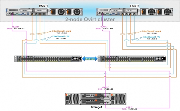
For network interaction between oVirt hosts and virtual machines, as well as for managing our SAN, it is necessary to configure the stack of Cisco 2960X switches.
Dell hosts have built-in 4-port network cards; therefore, it is advisable to organize their connection to the Cisco 2960X using a fault-tolerant network connection by grouping physical network ports into a logical interface, using the LACP (802.3ad) protocol:
- the first two ports on the host are configured in bonding mode and connected to the 2960X switch – this logical interface will be configured bridge with an address for managing the host, monitoring, and communicating with other hosts in the oVirt cluster; it will also be used for Live migration of virtual machines;
- the second two ports on the host are also configured in bonding mode and connected to the 2960X – on this logical interface, using oVirt, bridges will later be created (in the appropriate VLANs) to which virtual machines will connect.
- both network ports, within one logical interface, will be active, meaning traffic can be transmitted through them simultaneously in load balancing mode.
- network settings on the cluster nodes must be absolutely IDENTICAL, except for the IP addresses.
Basic switch stack configuration 2960X and its ports
Our switches must be pre-configured as follows:
- rack-mounted;
- connected via two special cables of the required length, for example, CAB-STK-E-1M;
- connected to power supply;
- connected to the administrator's workstation through the console port for initial configuration.
Necessary guidance for this is available on the of the manufacturer.
After completing the above actions, we configure the switches.
What each command means will not be detailed in this article; if necessary, all the information can be found independently.
Our goal is to configure the switch stack as quickly as possible and connect hosts and management interfaces to the storage system.
1) Connect to the main switch, enter privileged mode, then enter configuration mode and perform the basic settings.
Basic switch configuration:
 enable
 configure terminal

 hostname 2960X

 no service pad
 service timestamps debug datetime msec
 service timestamps log datetime localtime show-timezone msec
 no service password-encryption
 service sequence-numbers

 switch 1 priority 15
 switch 2 priority 14
 stack-mac persistent timer 0

 clock timezone MSK 3
  vtp mode transparent
  ip subnet-zero

 vlan 17
  name Management

 vlan 32
  name PROD

 vlan 33
  name Interconnect

 vlan 34
  name Test

 vlan 35
  name Dev

 vlan 40
  name Monitoring

 spanning-tree mode rapid-pvst
 spanning-tree etherchannel guard misconfig
 spanning-tree portfast bpduguard default
 spanning-tree extend system-id
 spanning-tree vlan 1-40 root primary
 spanning-tree loopguard default
 vlan internal allocation policy ascending
 port-channel load-balance src-dst-ip

 errdisable recovery cause loopback
 errdisable recovery cause bpduguard
 errdisable recovery interval 60

line con 0
 session-timeout 60
 exec-timeout 60 0
 logging synchronous
line vty 5 15
 session-timeout 60
 exec-timeout 60 0
 logging synchronous

 ip http server
 ip http secure-server
 no vstack

interface Vlan1
 no ip address
 shutdown

 exit
We save the config with the command "wr mem" and restart the switch stack using the command "reload" on the primary switch switch 1.
2) We configure the switch ports to access mode in VLAN 17 for connecting management interfaces of storage systems and iDRAC servers.
Management port configuration:
interface GigabitEthernet1/0/5
 description iDRAC - host1
 switchport access vlan 17
 switchport mode access
 spanning-tree portfast edge

interface GigabitEthernet1/0/6
 description Storage1 - Cntr0/Eth0
 switchport access vlan 17
 switchport mode access
 spanning-tree portfast edge

interface GigabitEthernet2/0/5
 description iDRAC - host2
 switchport access vlan 17
 switchport mode access
 spanning-tree portfast edge

interface GigabitEthernet2/0/6
 description Storage1 – Cntr1/Eth0
 switchport access vlan 17
 switchport mode access
 spanning-tree portfast edge
 exit
3) After restarting the stack, we check that it operates correctly:
Checking stack functionality:
2960X#show switch stack-ring speed

Stack Ring Speed        : 20G
Stack Ring Configuration: Full
Stack Ring Protocol     : FlexStack

2960X#show switch stack-ports
  Switch #    Port 1       Port 2
  --------    ------       ------
    1           Ok           Ok
    2           Ok           Ok

2960X#show switch neighbors
  Switch #    Port 1       Port 2
  --------    ------       ------
      1         2             2
      2         1             1

2960X#show switch detail
Switch/Stack Mac Address : 0cd0.f8e4.XXXX
Mac persistency wait time: Indefinite
                                           H/W   Current
Switch#  Role   Mac Address     Priority Version  State
----------------------------------------------------------
*1       Master 0cd0.f8e4.XXXX    15     4       Ready
 2       Member 0029.c251.XXXX     14     4       Ready

         Stack Port Status             Neighbors
Switch#  Port 1     Port 2           Port 1   Port 2
--------------------------------------------------------
  1        Ok         Ok                2        2
  2        Ok         Ok                1        1
4) Configuring SSH access to the 2960X stack
For remote management of the stack via SSH, we will use IP 172.20.1.10, configured on the SVI (switch virtual interface) VLAN17.
While it is advisable to use a dedicated port on the switch for management purposes, this is a matter of personal preference and capability.
Configuring SSH access to the switch stack:
ip default-gateway 172.20.1.2

interface vlan 17
 ip address 172.20.1.10 255.255.255.0

hostname 2960X
 ip domain-name hw.home-lab.ru
 no ip domain-lookup

clock set 12:47:04 06 Dec 2019

crypto key generate rsa

ip ssh version 2
ip ssh time-out 90

line vty 0 4
 session-timeout 60
 exec-timeout 60 0
 privilege level 15
 logging synchronous
 transport input ssh

line vty 5 15
 session-timeout 60
 exec-timeout 60 0
 privilege level 15
 logging synchronous
 transport input ssh

aaa new-model
aaa authentication login default local
username cisco privilege 15 secret my_ssh_password
Setting up the password for privileged mode access:
enable secret *myenablepassword*
service password-encryption
Configuring NTP:
ntp server 85.21.78.8 prefer
ntp server 89.221.207.113
ntp server 185.22.60.71
ntp server 192.36.143.130
ntp server 185.209.85.222

show ntp status
show ntp associations
show clock detail
5) Configuring EtherChannel logical interfaces and physical ports connected to hosts. For simplicity, all existing VLANs will be allowed on all logical interfaces, but it is generally recommended to configure only what is necessary:
Configuring EtherChannel interfaces:
interface Port-channel1
 description EtherChannel with Host1-management
 switchport trunk allowed vlan 10,17,30-40
 switchport mode trunk
 spanning-tree portfast edge trunk

interface Port-channel2
 description EtherChannel with Host2-management
 switchport trunk allowed vlan 10,17,30-40
 switchport mode trunk
 spanning-tree portfast edge trunk

interface Port-channel3
 description EtherChannel with Host1-VM
 switchport trunk allowed vlan 10,17,30-40
 switchport mode trunk
 spanning-tree portfast edge trunk

interface Port-channel4
 description EtherChannel with Host2-VM
 switchport trunk allowed vlan 10,17,30-40
 switchport mode trunk
 spanning-tree portfast edge trunk

interface GigabitEthernet1/0/1
 description Host1-management
 switchport trunk allowed vlan 10,17,30-40
 switchport mode trunk
 channel-protocol lacp
 channel-group 1 mode active

interface GigabitEthernet1/0/2
 description Host2-management
 switchport trunk allowed vlan 10,17,30-40
 switchport mode trunk
 channel-protocol lacp
 channel-group 2 mode active

interface GigabitEthernet1/0/3
 description Host1-VM
 switchport trunk allowed vlan 10,17,30-40
 switchport mode trunk
 channel-protocol lacp
 channel-group 3 mode active

interface GigabitEthernet1/0/4
 description Host2-VM
 switchport trunk allowed vlan 10,17,30-40
 switchport mode trunk
 channel-protocol lacp
 channel-group 4 mode active

interface GigabitEthernet2/0/1
 description Host1-management
 switchport trunk allowed vlan 10,17,30-40
 switchport mode trunk
 channel-protocol lacp
 channel-group 1 mode active

interface GigabitEthernet2/0/2
 description Host2-management
 switchport trunk allowed vlan 10,17,30-40
 switchport mode trunk
 channel-protocol lacp
 channel-group 2 mode active

interface GigabitEthernet2/0/3
 description Host1-VM
 switchport trunk allowed vlan 10,17,30-40
 switchport mode trunk
 channel-protocol lacp
 channel-group 3 mode active

interface GigabitEthernet2/0/4
 description Host2-VM
 switchport trunk allowed vlan 10,17,30-40
 switchport mode trunk
 channel-protocol lacp
 channel-group 4 mode active
Initial configuration of network interfaces for virtual machines on hosts Host1 and Host2
Checking for the required bonding modules in the system, installing the module for managing bridges:
modinfo bonding
modinfo 8021q
yum install bridge-utils
Configuring the logical interface BOND1 on the hosts for virtual machines, and its physical interfaces:
cat /etc/sysconfig/network-scripts/ifcfg-bond1
#DESCRIPTION - management
DEVICE=bond1
NAME=bond1
TYPE=Bond
IPV6INIT=no
ONBOOT=yes
USERCTL=no
NM_CONTROLLED=no
BOOTPROTO=none
BONDING_OPTS='mode=4 lacp_rate=1 xmit_hash_policy=2'

cat /etc/sysconfig/network-scripts/ifcfg-em2
#DESCRIPTION - management
DEVICE=em2
TYPE=Ethernet
BOOTPROTO=none
ONBOOT=yes
MASTER=bond1
SLAVE=yes
USERCTL=no
NM_CONTROLLED=no

cat /etc/sysconfig/network-scripts/ifcfg-em3
#DESCRIPTION - management
DEVICE=em3
TYPE=Ethernet
BOOTPROTO=none
ONBOOT=yes
MASTER=bond1
SLAVE=yes
USERCTL=no
NM_CONTROLLED=no
After completing the settings on the stack 2960X and hosts, we restart the network on the hosts and check the functionality of the logical interface.
- on the host:
systemctl restart network

cat /proc/net/bonding/bond1
Ethernet Channel Bonding Driver: v3.7.1 (April 27, 2011)

Bonding Mode: IEEE 802.3ad Dynamic link aggregation
Transmit Hash Policy: layer2+3 (2)
MII Status: up
MII Polling Interval (ms): 100
Up Delay (ms): 0
Down Delay (ms): 0
...
802.3ad info
LACP rate: fast
Min links: 0
Aggregator selection policy (ad_select): stable
System priority: 65535
...
Slave Interface: em2
MII Status: up
Speed: 1000 Mbps
Duplex: full
...
Slave Interface: em3
MII Status: up
Speed: 1000 Mbps
Duplex: full- on the switch stack 2960X:
2960X#show lacp internal
Flags:  S - Device is requesting Slow LACPDUs
        F - Device is requesting Fast LACPDUs
        A - Device is in Active mode       P - Device is in Passive mode

Channel group 1
                            LACP port     Admin     Oper    Port        Port
Port      Flags   State     Priority      Key       Key     Number      State
Gi1/0/1   SA      bndl      32768         0x1       0x1     0x102       0x3D
Gi2/0/1   SA      bndl      32768         0x1       0x1     0x202       0x3D

2960X#sh etherchannel summary
Flags:  D - down        P - bundled in port-channel
        I - stand-alone s - suspended
        H - Hot-standby (LACP only)
        R - Layer3      S - Layer2
        U - in use      N - not in use, no aggregation
        f - failed to allocate aggregator

        M - not in use, minimum links not met
        m - not in use, port not aggregated due to minimum links not met
        u - unsuitable for bundling
        w - waiting to be aggregated
        d - default port

        A - formed by Auto LAG

Number of channel-groups in use: 11
Number of aggregators:           11

Group  Port-channel  Protocol    Ports
------+-------------+-----------+-----------------------------------------------
1      Po1(SU)         LACP      Gi1/0/1(P)  Gi2/0/1(P)
Initial configuration of network interfaces for managing cluster resources on hosts Host1 and Host2
Configuring the logical interface BOND1 on the hosts for management, and its physical interfaces:
cat /etc/sysconfig/network-scripts/ifcfg-bond0
#DESCRIPTION - management
DEVICE=bond0
NAME=bond0
TYPE=Bond
BONDING_MASTER=yes
IPV6INIT=no
ONBOOT=yes
USERCTL=no
NM_CONTROLLED=no
BOOTPROTO=none
BONDING_OPTS='mode=4 lacp_rate=1 xmit_hash_policy=2'

cat /etc/sysconfig/network-scripts/ifcfg-em0
#DESCRIPTION - management
DEVICE=em0
TYPE=Ethernet
BOOTPROTO=none
ONBOOT=yes
MASTER=bond0
SLAVE=yes
USERCTL=no
NM_CONTROLLED=no

cat /etc/sysconfig/network-scripts/ifcfg-em1
#DESCRIPTION - management
DEVICE=em1
TYPE=Ethernet
BOOTPROTO=none
ONBOOT=yes
MASTER=bond0
SLAVE=yes
USERCTL=no
NM_CONTROLLED=no
After completing the settings on the stack 2960X and hosts, we restart the network on the hosts and check the functionality of the logical interface.
systemctl restart network
cat /proc/net/bonding/bond1

2960X#show lacp internal
2960X#sh etherchannel summary
Setting up the management network interface on each host in VLAN 17, and linking it to the logical interface BOND1:
Configuring VLAN17 on Host1:
cat /etc/sysconfig/network-scripts/ifcfg-bond1.17
DEVICE=bond1.17
NAME=bond1-vlan17
BOOTPROTO=none
ONBOOT=yes
USERCTL=no
NM_CONTROLLED=no
VLAN=yes
MTU=1500
IPV4_FAILURE_FATAL=yes
IPV6INIT=no
IPADDR=172.20.17.163
NETMASK=255.255.255.0
GATEWAY=172.20.17.2
DEFROUTE=yes
DNS1=172.20.17.8
DNS2=172.20.17.9
ZONE=public
Configuring VLAN17 on Host2:
cat /etc/sysconfig/network-scripts/ifcfg-bond1.17
DEVICE=bond1.17
NAME=bond1-vlan17
BOOTPROTO=none
ONBOOT=yes
USERCTL=no
NM_CONTROLLED=no
VLAN=yes
MTU=1500
IPV4_FAILURE_FATAL=yes
IPV6INIT=no
IPADDR=172.20.17.164
NETMASK=255.255.255.0
GATEWAY=172.20.17.2
DEFROUTE=yes
DNS1=172.20.17.8
DNS2=172.20.17.9
ZONE=public
We will restart the network on the hosts and check their visibility with each other.
At this point, the configuration of the Cisco 2960X switch stack is complete, and if everything has been done correctly, we now have network connectivity between all infrastructure elements at L2.
Configuring the Dell MD3820f SAN
Before starting the configuration of the SAN, it should already be connected to the Cisco switch stack 2960X through management interfaces, as well as to the hosts Host1 and Host2 via FC.
The overall diagram of how the SAN should be connected to the switch stack was provided in the previous chapter.
The diagram of connecting the SAN via FC to the hosts should look like this:
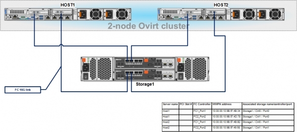
During the connection, it is necessary to record the WWPN addresses for the FC HBAs of the hosts connected to the FC ports on the SAN – this will be necessary for later configuration of host binding to LUNs on the SAN.
On the administrator's workstation, we download and install the utility for managing the Dell MD3820f – PowerVault Modular Disk Storage Manager (MDSM).
We connect to it via its default IP addresses, and then configure our addresses from VLAN17, for managing controllers via TCP/IP:
Storage1:
ControllerA IP - 172.20.1.13, MASK - 255.255.255.0, Gateway - 172.20.1.2
ControllerB IP - 172.20.1.14, MASK - 255.255.255.0, Gateway - 172.20.1.2
After configuring the addresses, we access the SAN management interface and set the password, configure the time, update the firmware for the controllers and disks, if necessary, etc.
How this is done is described in Storage Array.
After completing the settings mentioned above, we need to perform just a few actions:
- Configure host FC port identifiers – Host Port Identifiers.
- Create a host group – Host group and add our two Dell hosts to it.
- Create a disk group and virtual disks (or LUNs) within it, which will be presented to the hosts.
- Configure the presentation of virtual disks (or LUNs) for the hosts.
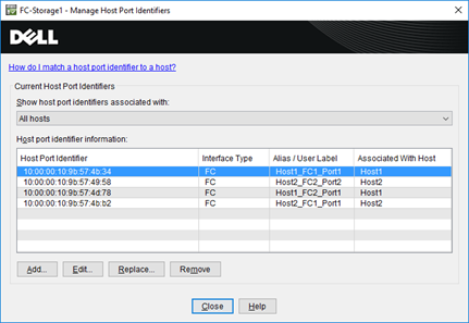
Adding new hosts and binding them to host FC port identifiers is done through the menu – Host Mappings -> Define -> Hosts…
The WWPN addresses of the FC HBAs of the hosts can be found, for example, in the server's iDRAC.
As a result, we should end up with an image like this:
Adding a new host group and binding hosts to it is done through the menu – Host Mappings -> Define -> Host Group…
For hosts, select the OS type – Linux (DM-MP).
After creating the host group, through the tab Storage & Copy Services, we create a disk group – Disk Group, with a type depending on the redundancy requirements, for example, RAID10, and within it, virtual disks of the desired size:
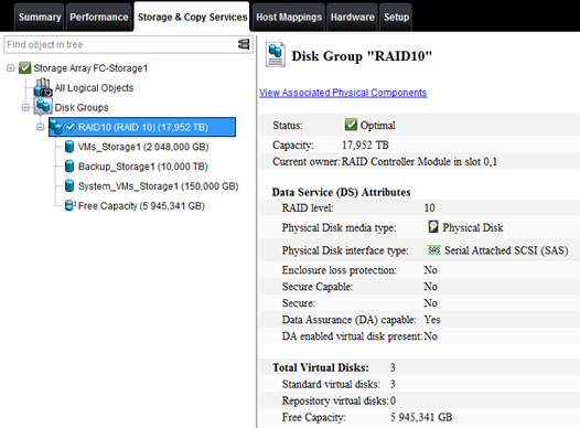
And finally, the last step — presenting the virtual disks (or LUNs) to the hosts.
To do this through the menu – Host Mappings -> Lun mapping -> Add… we bind the virtual disks to the hosts, assigning them numbers.
Everything should look like this screenshot:
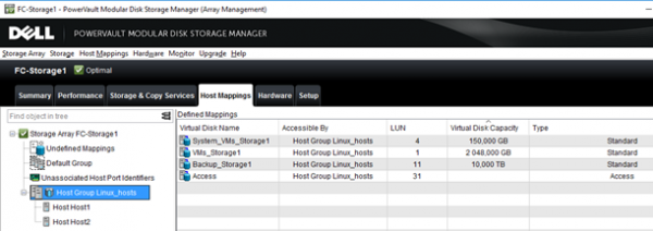
With the SAN setup, we conclude, and if everything was done correctly, the hosts should see the presented LUNs through their FC HBAs.
Let's force the system to refresh the information about connected disks:
ls -la /sys/class/scsi_host/
echo "- - -" > /sys/class/scsi_host/host[0-9]/scan
Let's see what devices are visible on our servers:
cat /proc/scsi/scsi
Attached devices:
Host: scsi0 Channel: 02 Id: 00 Lun: 00
  Vendor: DELL     Model: PERC H330 Mini   Rev: 4.29
  Type:   Direct-Access                    ANSI SCSI revision: 05
Host: scsi15 Channel: 00 Id: 00 Lun: 00
  Vendor: DELL     Model: MD38xxf          Rev: 0825
  Type:   Direct-Access                    ANSI SCSI revision: 05
Host: scsi15 Channel: 00 Id: 00 Lun: 01
  Vendor: DELL     Model: MD38xxf          Rev: 0825
  Type:   Direct-Access                    ANSI SCSI revision: 05
Host: scsi15 Channel: 00 Id: 00 Lun: 04
  Vendor: DELL     Model: MD38xxf          Rev: 0825
  Type:   Direct-Access                    ANSI SCSI revision: 05
Host: scsi15 Channel: 00 Id: 00 Lun: 11
  Vendor: DELL     Model: MD38xxf          Rev: 0825
  Type:   Direct-Access                    ANSI SCSI revision: 05
Host: scsi15 Channel: 00 Id: 00 Lun: 31
  Vendor: DELL     Model: Universal Xport  Rev: 0825
  Type:   Direct-Access                    ANSI SCSI revision: 05
Host: scsi18 Channel: 00 Id: 00 Lun: 00
  Vendor: DELL     Model: MD38xxf          Rev: 0825
  Type:   Direct-Access                    ANSI SCSI revision: 05
Host: scsi18 Channel: 00 Id: 00 Lun: 01
  Vendor: DELL     Model: MD38xxf          Rev: 0825
  Type:   Direct-Access                    ANSI SCSI revision: 05
Host: scsi18 Channel: 00 Id: 00 Lun: 04
  Vendor: DELL     Model: MD38xxf          Rev: 0825
  Type:   Direct-Access                    ANSI SCSI revision: 05
Host: scsi18 Channel: 00 Id: 00 Lun: 11
  Vendor: DELL     Model: MD38xxf          Rev: 0825
  Type:   Direct-Access                    ANSI SCSI revision: 05
Host: scsi18 Channel: 00 Id: 00 Lun: 31
  Vendor: DELL     Model: Universal Xport  Rev: 0825
  Type:   Direct-Access                    ANSI SCSI revision: 05

lsscsi
[0:2:0:0]    disk    DELL     PERC H330 Mini   4.29  /dev/sda
[15:0:0:0]   disk    DELL     MD38xxf          0825  -
[15:0:0:1]   disk    DELL     MD38xxf          0825  /dev/sdb
[15:0:0:4]   disk    DELL     MD38xxf          0825  /dev/sdc
[15:0:0:11]  disk    DELL     MD38xxf          0825  /dev/sdd
[15:0:0:31]  disk    DELL     Universal Xport  0825  -
 [18:0:0:0]   disk    DELL     MD38xxf          0825  -
[18:0:0:1]   disk    DELL     MD38xxf          0825  /dev/sdi
[18:0:0:4]   disk    DELL     MD38xxf          0825  /dev/sdj
[18:0:0:11]  disk    DELL     MD38xxf          0825  /dev/sdk
[18:0:0:31]  disk    DELL     Universal Xport  0825  -
On hosts, you can also set up additionally multipath, and although oVirt can do this itself during installation, it is better to check the correctness of MP operation in advance yourself.
Installation and configuration of DM Multipath
yum install device-mapper-multipath
mpathconf --enable --user_friendly_names y

cat /etc/multipath.conf | egrep -v "^s*(#|$)"
defaults {
    user_friendly_names yes
            find_multipaths yes
}

blacklist {
  wwid 26353900f02796769
  devnode "^(ram|raw|loop|fd|md|dm-|sr|scd|st)[0-9]*"
  devnode "^hd[a-z]"
 }
We set the MP service to auto-start and start it:
systemctl enable multipathd && systemctl restart multipathdChecking information about loaded modules for MP operation:
lsmod | grep dm_multipath
dm_multipath           27792  6 dm_service_time
dm_mod                124407  139 dm_multipath,dm_log,dm_mirror

modinfo dm_multipath
filename:       /lib/modules/3.10.0-957.12.2.el7.x86_64/kernel/drivers/md/dm-multipath.ko.xz
license:        GPL
author:         Sistina Software
description:    device-mapper multipath target
retpoline:      Y
rhelversion:    7.6
srcversion:     985A03DCAF053D4910E53EE
depends:        dm-mod
intree:         Y
vermagic:       3.10.0-957.12.2.el7.x86_64 SMP mod_unload modversions
signer:         CentOS Linux kernel signing key
sig_key:        A3:2D:39:46:F2:D3:58:EA:52:30:1F:63:37:8A:37:A5:54:03:00:45
sig_hashalgo:   sha256
Viewing summary information about the existing multipath configuration:
mpathconf
multipath is enabled
find_multipaths is disabled
user_friendly_names is disabled
dm_multipath module is loaded
multipathd is running
After adding a new LUN to the storage system and presenting it to the host, it needs to scan the connected HBAs.
systemctl reload multipathd
multipath -v2
Finally, check if all LUNs have been presented by the storage system to the hosts and whether there are two paths to each.
MP operation check:
multipath -ll
3600a098000e4b4b3000003175cec1840 dm-2 DELL    ,MD38xxf
size=2.0T features='3 queue_if_no_path pg_init_retries 50' hwhandler='1 rdac' wp=rw
|-+- policy='service-time 0' prio=14 status=active
| `- 15:0:0:1  sdb 8:16  active ready running
`-+- policy='service-time 0' prio=9 status=enabled
  `- 18:0:0:1  sdi 8:128 active ready running
3600a098000e4b48f000002ab5cec1921 dm-6 DELL    ,MD38xxf
size=10T features='3 queue_if_no_path pg_init_retries 50' hwhandler='1 rdac' wp=rw
|-+- policy='service-time 0' prio=14 status=active
| `- 18:0:0:11 sdk 8:160 active ready running
`-+- policy='service-time 0' prio=9 status=enabled
  `- 15:0:0:11 sdd 8:48  active ready running
3600a098000e4b4b3000003c95d171065 dm-3 DELL    ,MD38xxf
size=150G features='3 queue_if_no_path pg_init_retries 50' hwhandler='1 rdac' wp=rw
|-+- policy='service-time 0' prio=14 status=active
| `- 15:0:0:4  sdc 8:32  active ready running
`-+- policy='service-time 0' prio=9 status=enabled
  `- 18:0:0:4  sdj 8:144 active ready running
As can be seen, all three virtual disks on the storage system are visible through two paths. Thus, all preparatory work has been completed, and we can move on to the main part - the setup of the oVirt cluster, which will be discussed in the next article.
Source: habr.com
