

In the previous post about we discussed that some racks are equipped with an automatic transfer switch (ATS). However, in reality, ATS is installed not only in the rack but also throughout the entire electricity supply path. They serve different purposes in various locations:
- In the main distribution boards (MDBs), ATS switches the load between the city power input and backup power from diesel generator units (DGU);
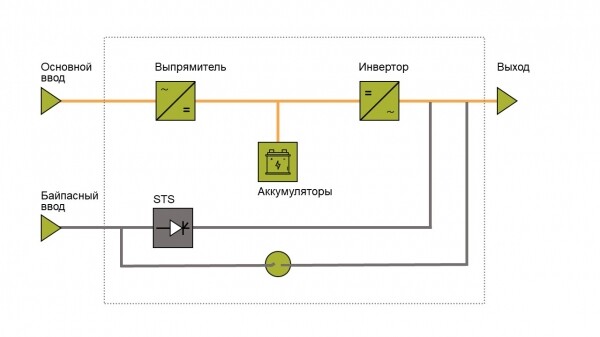
- In uninterruptible power supplies (UPS), ATS switches the load from the main input to the bypass (more on this later);
- In racks, ATS switches the load from one input to another in case of issues with one of the inputs.
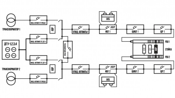
ATS in the standard power supply scheme of DataLine data centers.
Today, we will discuss the types of ATS and where they are used.
There are two main types of ATS: ATS (automatic transfer switch) and STS (static transfer switch). They differ in their operating principles and component bases and are used for different tasks. Briefly, STS is a more 'intelligent' ATS. It switches the load faster and is more often used for larger loads/currents. It is more flexible in configuration but has 'quirks' with the network: it may refuse to operate if the two inputs are powered from different sources, for example, from a transformer and a DGU.
ATS in MDB
Twenty years ago, the main ATS of a data center looked like a complex system of contactors and relays.
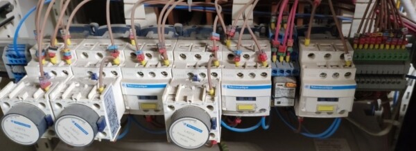
ATS from the early 2000s.
Today, ATS is a compact multifunctional device.
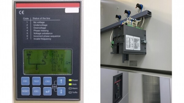
The ATS system in MDB manages the input circuit breakers and gives commands to start and stop the DGU. At loads above 2 MW at the MDB level, it's unreasonable to chase speed. Even if it switches quickly, there will be a delay before the DGU starts. In this system, 'slower' ATS are used, and delays (setpoints) are established. It works like this: when the power to the data center from the transformers goes out, the ATS instructs the devices: 'Transformer, turn off. Now, wait 10 seconds (setpoint), DGU, turn on, wait another 10 seconds.'
ATS in UPS
Let's use the UPS as an example to see how the second type of ATS — STS or static transfer switch — works.
In the UPS, alternating current is converted to direct current in the rectifier. Then, in the inverter, it is turned back into alternating current, but with stable parameters. This eliminates noise and improves energy quality. When the main power source is disconnected to battery power and supplies the data center while the diesel generator starts up.
But what if one of the components fails: the rectifier, inverter, or battery? In that case, each UPS has a bypass mechanism. With it, the device continues operating by bypassing the main components, directly from the input voltage. The bypass is also used when it is necessary to turn off the UPS and send it for repair.
STS in the UPS is needed to safely switch to the bypass input. In short, STS monitors the network parameters at the input and output, waits for them to match, and switches under safe conditions.
AVR in the rack
So, there are two power inputs connected to the rack. If your equipment has two power supplies, you can safely connect it to different PDUs, and losing one input won't be a problem. But what if your server has only one power supply?
In the rack, AVR is used to ensure that the benefits of two inputs are not wasted. In case of issues with one of the inputs, the AVR switches the load to the other input.
Disclaimer: If possible, avoid equipment with a single power supply to prevent creating a single point of failure in the system. Next, we will demonstrate the drawbacks of this connection scheme.

The task of AVR in the rack is to switch the equipment to the operational input as quickly as possible, ensuring there is no interruption in its operation. The required speed has been determined experimentally: no more than 20 ms. Let's see how this was discovered.
Failures in server equipment occur due to voltage drops (from work on substations, connecting heavy loads, or accidents). To illustrate how the equipment withstands different amplitudes and durations of voltage fluctuations, the safe operating curves for electrical equipment were developed by CBEMA (Computer and Business Equipment Manufacturers Association). They are now known as ITIC curves (Information Technology Industry Council), with their variants included in the IEEE 446 ANSI standards (analogous to our GOSTs).
Let's refer to the chart. Our task is to ensure that the devices operate in the 'green zone.' On the ITIC curve, we see that the equipment is ready to 'endure' a drop for a maximum of 20 ms. Thus, we aim for the AVR in the rack to act within 20 ms, or better yet, even faster.
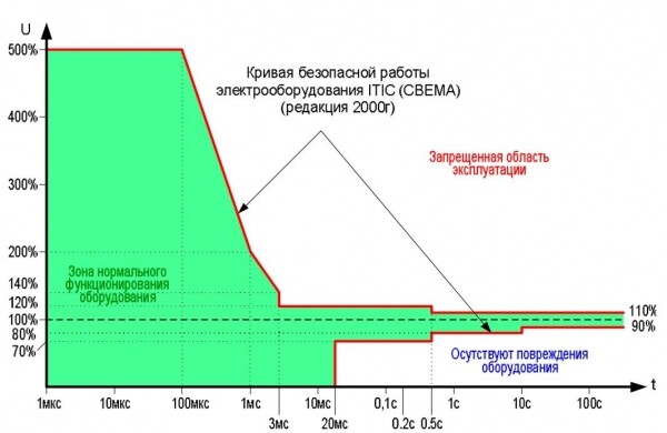
Source: .
The AVR deviceThe typical ATS in our data center occupies 1U and supports a load of 16 A.
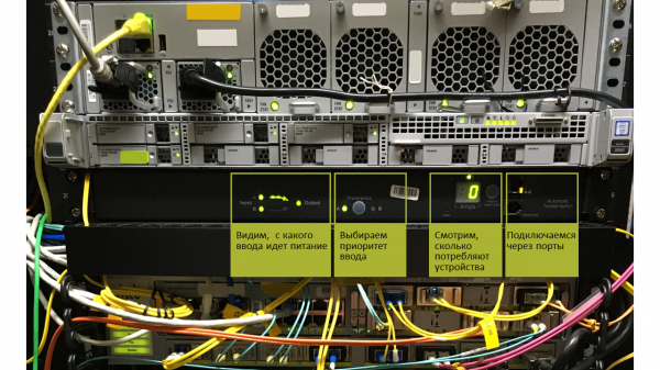
On the display, we can see which input the ATS is powered from and how much the connected devices consume in amperes. With a separate button, we choose to prioritize either the first or the second input. On the right are the ports for connecting to the ATS:
- Ethernet port — to connect monitoring;
- Serial port — to access via laptop and check the logs for what’s happening;
- USB — insert a flash drive and update the firmware.
The ports are interchangeable: all these operations can be performed if at least one of them is accessible.
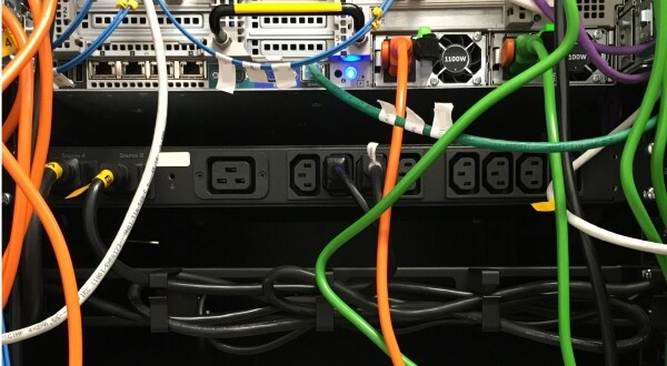
On the back side — plugs for connecting the main and backup inputs, and a socket group for connecting IT equipment.
We view detailed specifications of the ATS through the web interface. Here we can adjust the switching sensitivity and see logs.
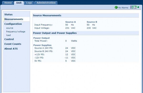
Web interface of the ATS.
Installation and connection of the ATSThe ATS should be installed at mid-height in the rack. If we do not know the rack configuration in advance, this way the equipment with one power supply can reach both the bottom and top parts with cables.
However, there are nuances: the depth of a standard rack is much greater than the depth of the ATS. We recommend installing it as close as possible to the cold aisle for two reasons:
- Access to the front panel. If the ATS is installed closer to the hot aisle, we will see the indication, but we won’t be able to connect to it through the ports. This means we won’t be able to check logs or reboot the device.


Somewhere deep inside, the ATS is blinking — we can't reach the port anymore. - Cooling. The ATS is recommended to be used at temperatures not exceeding 45°C. It does not have its own cooling fans; it's simply a metallic device with electronic components. It maintains the required temperature in two ways:
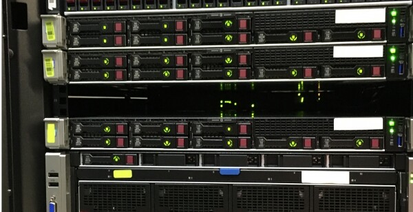
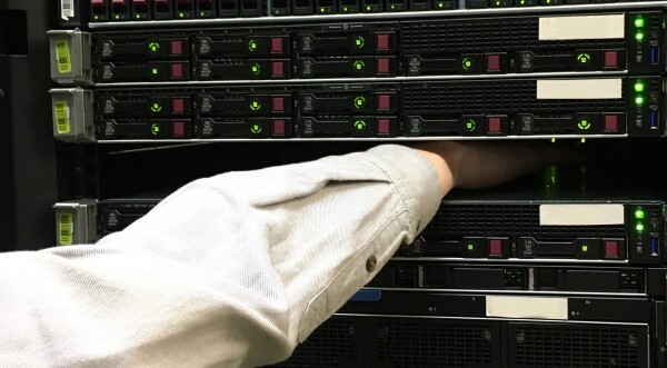
- airflows blowing on it from the outside;
- mounts that dissipate excess heat.
If the ATS is installed on the hot aisle side, and additionally surrounded by a layer of servers, we will create an oven. In the best case, the ATS will burn out its circuitry and lose connection with the outside world; in the worst case — it will start switching loads chaotically or drop them.
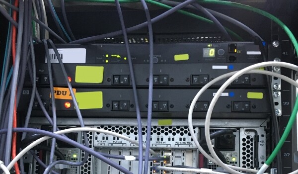
The ATS is sweating facing the hot aisle.
There was a case. An engineer heard unusual clicks during an inspection.
In the depths of the hot aisle under a pile of servers, an AVR was found, constantly switching from the main input to the backup.The AVR has been replaced. Logs showed that it switched every second for an entire week — totaling over half a million switches. This is how it happened.
What other AVRs are there in the rack?
Input ATS for the rack.. In our data center, this AVR serves as the sole source of power distribution in the rack: it works as an AVR+PDU. It occupies several units, withstands a load of 32 A, connects with industrial connectors, and can power up to 6 kW of equipment. It can be used when there is no possibility to install standard PDUs, and single-block equipment in the rack does not handle critical loads.
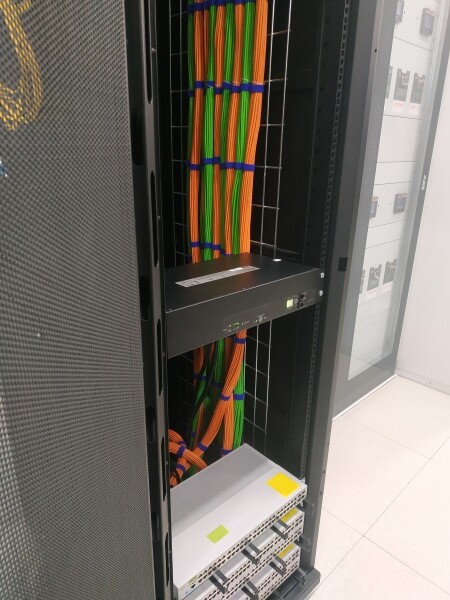
Rack-mount STS. STS in the rack is used for equipment sensitive to voltage fluctuations. This AVR switches faster than an ATS.
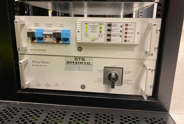
This particular STS occupies 6 units and has a somewhat 'vintage' interface.
Mini-AVR. There are such little ones, but we don’t have any in our data center. This is a mini-AVR for one server.
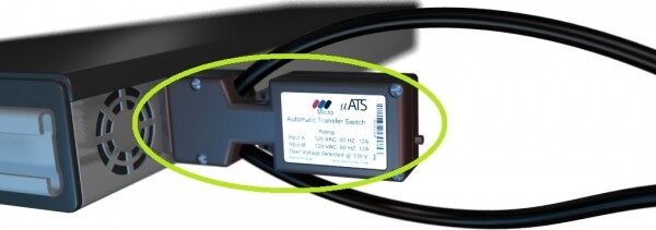
This AVR connects directly to the server's power supply.
How we search for the ideal AVR
We test many different AVRs and check how they behave under high temperatures.
Here’s how we put the AVRs to the test to verify this:
- we connect a network quality recorder, a server, and several other devices to apply load;
- we isolate the rack with plugs or film to reach high temperatures;
- we heat it up to 50°C;
- we sequentially turn off the inputs 20 times;
- we check for power failures and observe how the server performs;
- if the AVR passes the test — we heat it up to 70°C.
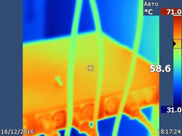
Thermal imaging photo from one of the tests.
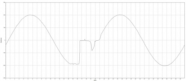
The network analyzer records the voltage over time. The recording shows how long the switching lasted: at this moment, the sine wave was interrupted.
By the way, we are taking the AVR for testing: we’ll check your device for durability and let you know how it performed 😉
AVR in the rack: a hidden threat.
The main issue with an Automatic Transfer Switch (ATS) in a rack is that it only switches the load from the main power source to the backup input, but does not protect against short circuits or overloads. If a short circuit occurs in the power supply, the protection will trigger the circuit breaker at the next level: on the PDU or in the distribution panel. As a result, one input turns off, and the ATS recognizes this and switches to the second input. If the short circuit still exists, the circuit breaker for the second input will trip. Thus, an issue with one piece of equipment can lead to power loss for the entire rack.
So I’ll repeat once more: think a thousand times before installing an ATS in a rack and using equipment with a single power supply.
Source: habr.com
