

Once upon a time, home automation systems, often referred to as "smart homes," were incredibly expensive and only the wealthy could afford them. Today, the market offers quite affordable kits with sensors, buttons/switches, and actuators for controlling lighting, sockets, ventilation, water supply, and other appliances. Even the most inexperienced DIY enthusiast can easily get started with creating devices for a smart home without breaking the bank.
Typically, the offered devices are either sensors or actuators. They allow for easy scenarios like "turn on the light when the motion sensor is triggered" or "the switch by the exit turns off the lights throughout the apartment." However, telemetry has been somewhat lacking. At best, it consists of graphs showing temperature and humidity or the instantaneous power consumption for a specific socket.
Recently, I installed water meters with pulse outputs. For every liter that passes through the meter, a reed switch activates and closes the contact. The next step is simple — connect to the wires and see how to make use of it. For instance, analyzing water consumption by hours and days of the week. If there are multiple water risers in the apartment, it’s more convenient to see all current readings on one screen rather than crawling into hard-to-reach niches with a flashlight.
Below, I will share my version of a device based on the ESP8266, which counts the pulses from the water meters and sends the readings to the smart home server via MQTT. We will program it in MicroPython using the uasyncio library. While creating the firmware, I encountered several interesting challenges, which I will also discuss in this article. Let's get started!
Scheme
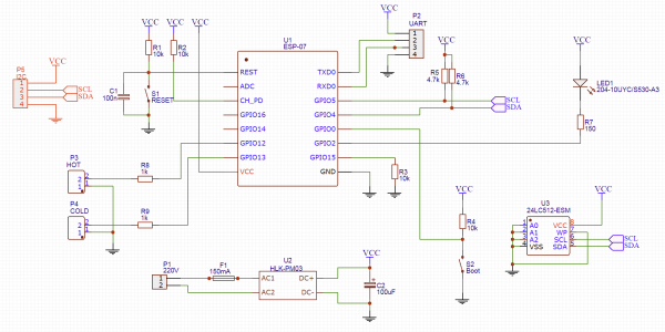
The heart of the entire setup is a module based on the ESP8266 microcontroller. Initially, I planned to use the ESP-12, but mine turned out to be defective. I had to settle for the ESP-07 module, which was available. Fortunately, they are identical in terms of pins and functionality, with the only difference being the antenna — the ESP-12 has a built-in antenna, while the ESP-07 has an external one. However, even without an antenna, the WiFi signal is decent in my bathroom.
The module wiring is standard:
- a reset button with a pull-up resistor and a capacitor (even though both are already present inside the module)
- The enable signal (CH_PD) is connected to the power supply
- GPIO15 is pulled down. This is only necessary at startup, but I don't need to connect anything to this leg anymore.
To put the module into programming mode, GPIO2 needs to be connected to ground. To make it more convenient, I provided a Boot button. In normal operation, this pin is pulled up to power.
The state of the GPIO2 line is checked only at the beginning of operation — when power is supplied or immediately after a reset. Thus, the module either boots up normally or enters programming mode. After booting, this pin can be used as a regular GPIO. Since there's a button, I can assign some useful function to it.
For programming and debugging, I will use UART, which is brought out to the header. When needed, I just connect a USB-UART adapter there. Just remember that the module runs on 3.3V. If I forget to switch the adapter to this voltage and supply 5V, the module will likely burn out.
I have no issues with electricity in the bathroom — the socket is located about a meter from the meters, so I will power it from 220V. I will be using a small from Tenstar Robot. Personally, I'm not skilled in analog and power electronics, and here’s a ready-made power supply in a small casing.
For signaling operating modes, I have provided an LED connected to GPIO2. However, I didn't solder it, as the ESP-07 module already has an LED connected to the same GPIO2. But it can remain on the board — just in case I want to bring this LED out to the case.
Now we move on to the most interesting part. The water meters have no logic; you can't query for the current readings. The only thing available is the pulses — contacts of the reed switch closing each liter. The reed switch outputs are connected to GPIO12/GPIO13. I will enable the pull-up resistor programmatically within the module.
Initially, I forgot to include resistors R8 and R9, and my version of the board does not have them. But since I am sharing the schematic for public view, it’s worth correcting this oversight. The resistors are needed to prevent burning the port in case the firmware glitches and sets a high value on the pin while the reed switch shorts the line to ground (with the resistor, a maximum of 3.3V/1000Ω = 3.3mA will flow).
It's time to think about what to do if the electricity goes out. The first option is to request initial values from the server at the start. However, this would significantly complicate the communication protocol. Moreover, the device's operability in such a case depends on the server's state. If the server doesn't start up after a power outage (or starts later), the water meter wouldn't be able to request initial values and would operate incorrectly.
Therefore, I decided to implement value retention for the meters in a memory chip connected via I2C. I have no special requirements for the flash memory size — I just need to save 2 numbers (the volume of hot and cold water used). Even the smallest module would suffice. However, attention should be paid to the number of write cycles. Most modules have about 100,000 cycles, with some reaching up to a million.
A million may sound like a lot. But in the 4 years I've lived in my apartment, I've consumed just over 500 cubic meters of water, which is 500,000 liters! That accounts for 500,000 writes to flash memory. And that's just for cold water. Of course, I could re-solder the chip every couple of years, but it turns out there are FRAM chips available. From a programming perspective, they operate like I2C EEPROM but have a significantly higher number of rewrite cycles (in the hundreds of millions). The only problem is that I haven’t managed to get to a store selling such chips yet, so for now, I will stick with the regular 24LC512.
Printed Circuit Board
Initially, I planned to manufacture the board at home. Therefore, the board was designed as a single-sided one. However, after struggling for an hour with the laser iron and solder mask (it's somehow not quite appropriate without it), I decided to order the boards from the Chinese.
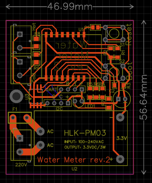
Just before placing the order for the boards, I realized that in addition to the flash memory chip, I could connect something else useful to the I2C bus, such as a display. What exactly to display on it is still a question, but I need to lay it out on the board. Since I was planning to order the boards from a factory, there was no point in limiting myself to a single-sided layout, so the I2C lines would be the only ones on the back side of the board.
One major mistake was also associated with the single-sided layout. Since the board was designed to be single-sided, the traces and SMD components were to be placed on one side, while the protruding components, connectors, and power supply were to be on the other. When I received the boards a month later, I forgot about the original plan and soldered all components on the front side. Only when it came time to solder the power supply did I realize that the positive and negative were reversed. I had to rig it with jumpers. In the image above, I've already changed the layout, but the ground wire crosses from one part of the board to another through the Boot button's leads (although I could have routed a trace on the second layer).
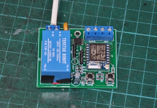
It turned out like this
Case
The next step is the case. With a 3D printer, this is no problem. I didn't overthink it — I just drew a box of the required size and made cutouts in the necessary places. The lid is attached to the case with small screws.
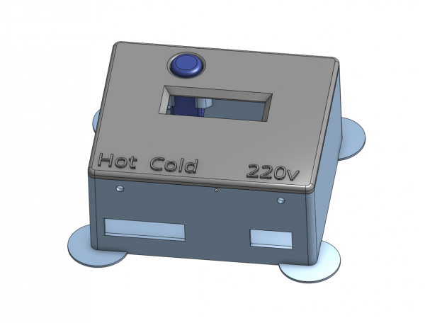
I've already mentioned that the Boot button can be used as a general-purpose button — so I'm going to bring it out to the front panel. For this, I drew a special "well" where the button resides.
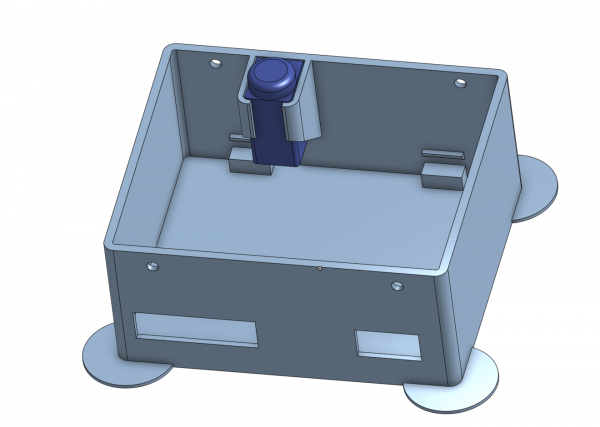
Inside the case, there are also stubs on which the board is installed and secured with a single M3 screw (there wasn't more space on the board).
I selected the display after printing the first mockup of the case. A standard two-line display wouldn't fit in this case, but I found an SSD1306 OLED display 128×32 in my stash. It's a bit small, but I don't need to look at it every day — it’ll do.
Considering how the wires would run from it, I decided to stick the display in the middle of the case. The ergonomics are, of course, below par — the button is on top, and the display is on the bottom. But as I said, the idea to attach the display came too late, and I was too lazy to revise the layout to move the button.
The device is assembled. The display module is glued down with hot glue.
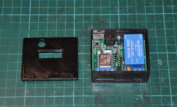
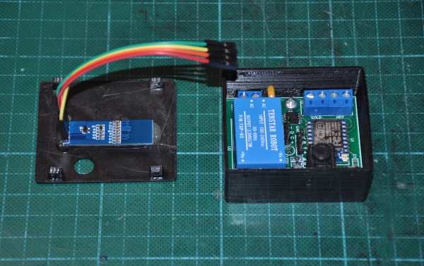
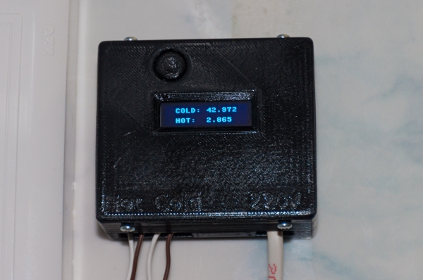
The final result can be seen on KDPV.
Firmware
Let's move on to the software part. For such small projects, I really like using the Python language ()- the code turns out to be very compact and understandable. Fortunately, there’s no need to drop down to the register level to squeeze out microseconds — everything can be done from Python.
It seems simple, but it’s not really — the device is set to perform several independent functions:
- The user presses the button and looks at the display
- The liters tick by and update values in flash memory
- The module monitors the WiFi signal and reconnects if necessary
- And without a blinking light, we can't proceed at all
We cannot allow one function to fail if another is lagging for any reason. I've had enough of cacti in other projects, and now I can clearly see glitches like 'missed another liter because the display was being updated at that moment' or 'the user can do nothing while the module connects to WiFi.' Sure, some things can be handled through interrupts, but you could hit limitations on duration, call nesting, or non-atomic variable changes. Plus, code that tries to do everything at once quickly turns into a mess.
In I used classic preemptive multitasking and FreeRTOS, but in this case, a different model is much more appropriate . Moreover, the Python implementation of coroutines is simply fantastic — everything is made simple and convenient for the programmer. Just write your logic; just indicate where to switch between threads.
I suggest studying the differences between preemptive and cooperative multitasking as an elective. Now, let's finally move on to the code.
#####################################
# Counter class - implements a single water counter on specified pin
#####################################
class Counter():
    debounce_ms = const(25)

    def __init__(self, pin_num, value_storage):
        self._value_storage = value_storage

        self._value = self._value_storage.read()
        self._value_changed = False

        self._pin = Pin(pin_num, Pin.IN, Pin.PULL_UP)

        loop = asyncio.get_event_loop()
        loop.create_task(self._switchcheck())  # Thread runs forever
Each counter is processed by an instance of the Counter class. First, the initial value of the counter is read from EEPROM (value_storage) — this implements recovery after a power failure.
The pin is initialized with an internal pull-up: if the reed switch is closed — there’s zero on the line, if it’s open the line pulls up to power, and the controller reads one.
There’s also a separate task started that will poll the pin. Each counter will start its own task. Here’s its code
    """ Poll pin and advance value when another litre passed """
    async def _switchcheck(self):
        last_checked_pin_state = self._pin.value()  # Get initial state

        # Poll for a pin change
        while True:
            state = self._pin.value()
            if state != last_checked_pin_state:
                # State has changed: act on it now.
                last_checked_pin_state = state
                if state == 0:
                    self._another_litre_passed()

            # Ignore further state changes until switch has settled
            await asyncio.sleep_ms(Counter.debounce_ms)
A 25ms delay is needed for contact bounce filtering, and it also regulates how often the task wakes up (while this task is sleeping, other tasks are running). Every 25ms, the function wakes up, checks the pin, and if the reed switch contacts are closed, it means another liter has passed through the counter, and this needs to be processed.
    def _another_litre_passed(self):
        self._value += 1
        self._value_changed = True

        self._value_storage.write(self._value)
Processing the next liter is straightforward — it simply increments the counter. Also, it would be good to record the new value to the flash.
To enhance usability, "accessors" are provided.
    def value(self):
        self._value_changed = False
        return self._value

    def set_value(self, value):
        self._value = value
        self._value_changed = False
Now let's take advantage of Python and the uasync library and make the counter object waitable (how to translate this into Russian? The one that can be awaited?).
    def __await__(self):
        while not self._value_changed:
            yield from asyncio.sleep(0)

        return self.value()

    __iter__ = __await__
This is a convenient function that waits for the counter's value to update — the function occasionally wakes up and checks the _value_changed flag. The trick of this function is that the calling code can sleep on this function call and stay asleep until a new value is received.
But what about interrupts?Yes, at this point, you might troll me, saying I mentioned interrupts, but in reality, I ended up doing simple pin polling. In fact, interrupts were the first thing I tried. On the ESP8266, you can set up an interrupt on the rising edge and even write the interrupt handler in Python. In this interrupt, you can update the variable's value. That would probably suffice if the counter were a slave device — one that waits for a request for its value.
Unfortunately (or fortunately?), my device is active; it should automatically send messages via the MQTT protocol and log data into EEPROM. Here, constraints come into play — you cannot allocate memory in interrupts or use a large stack, which means we can forget about sending messages over the network. There are features like micropython.schedule() that allow us to run a function 'as soon as possible,' but the question arises: 'What's the point?' What if we’re sending a message right now, and an interrupt occurs, messing up the variable values? Or, for example, a new counter value arrives from the server while we haven't finished writing the old one. In general, we need to build synchronization or find another way around it.
Also, from time to time, a RuntimeError: schedule stack full pops up, and who knows why?
With explicit polling and uasync, it looks somehow neater and more reliable in this case.
I've extracted the work with EEPROM into a small class.
class EEPROM():
    i2c_addr = const(80)

    def __init__(self, i2c):
        self.i2c = i2c
        self.i2c_buf = bytearray(4) # Avoid creation/destruction of the buffer on each call


    def read(self, eeprom_addr):
        self.i2c.readfrom_mem_into(self.i2c_addr, eeprom_addr, self.i2c_buf, addrsize=16)
        return ustruct.unpack_from("<I", self.i2c_buf)[0]


    def write(self, eeprom_addr, value):
        ustruct.pack_into("<I", self.i2c_buf, 0, value)
        self.i2c.writeto_mem(self.i2c_addr, eeprom_addr, self.i2c_buf, addrsize=16)
Working with bytes directly in Python is somewhat tricky, especially since it's bytes that get written to memory. I had to set up a conversion between integers and bytes using the ustruct library.
To avoid passing the I2C object and memory address every time, I wrapped everything in a small convenient class.
class EEPROMValue():
    def __init__(self, i2c, eeprom_addr):
        self._eeprom = EEPROM(i2c)
        self._eeprom_addr = eeprom_addr


    def read(self):
        return self._eeprom.read(self._eeprom_addr)


    def write(self, value):
        self._eeprom.write(self._eeprom_addr, value)
The I2C object is created with these parameters.
i2c = I2C(freq=400000, scl=Pin(5), sda=Pin(4))Now we get to the most interesting part — implementing communication with the server via MQTT. We don't need to implement the protocol itself — a ready-made asynchronous implementation can be found online. . This is what we’ll use.
All the interesting stuff is gathered in the CounterMQTTClient class, which is based on the library's MQTTClient. Let’s start with the peripherals.
#####################################
# Class handles both counters and sends their status to MQTT
#####################################
class CounterMQTTClient(MQTTClient):

    blue_led = Pin(2, Pin.OUT, value = 1)
    button = Pin(0, Pin.IN)

    hot_counter = Counter(12, EEPROMValue(i2c, EEPROM_ADDR_HOT_VALUE))
    cold_counter = Counter(13, EEPROMValue(i2c, EEPROM_ADDR_COLD_VALUE))
Here, the pins for the lamp and button are created and configured, as well as the objects for the cold and hot water counters.
Initialization is not trivial.
    def __init__(self):
        self.internet_outage = True
        self.internet_outages = 0
        self.internet_outage_start = ticks_ms()

        with open("config.txt") as config_file:
            config['ssid'] = config_file.readline().rstrip()
            config['wifi_pw'] = config_file.readline().rstrip()
            config['server'] = config_file.readline().rstrip()
            config['client_id'] = config_file.readline().rstrip()
            self._mqtt_cold_water_theme = config_file.readline().rstrip()
            self._mqtt_hot_water_theme = config_file.readline().rstrip()
            self._mqtt_debug_water_theme = config_file.readline().rstrip()

        config['subs_cb'] = self.mqtt_msg_handler
        config['wifi_coro'] = self.wifi_connection_handler
        config['connect_coro'] = self.mqtt_connection_handler
        config['clean'] = False
        config['clean_init'] = False
        super().__init__(config)

        loop = asyncio.get_event_loop()
        loop.create_task(self._heartbeat())
        loop.create_task(self._counter_coro(self.cold_counter, self._mqtt_cold_water_theme))
        loop.create_task(self._counter_coro(self.hot_counter, self._mqtt_hot_water_theme))
        loop.create_task(self._display_coro())
To configure the mqtt_as library, a large dictionary of various settings—config—is used. Most of the default settings suit our needs, but many need to be explicitly defined. To avoid hardcoding settings directly in the code, I store them in a text file, config.txt. This allows for changes to the code independent of the settings, as well as the ability to produce multiple identical devices with different parameters.
The last block of code launches several coroutines to service different system functions. For example, here is a coroutine that handles the counters.
    async def _counter_coro(self, counter, topic):
        # Publish initial value
        value = counter.value()
        await self.publish(topic, str(value))

        # Publish each new value
        while True:
            value = await counter
            await self.publish_msg(topic, str(value))
The coroutine waits for a new counter value in a loop and, as soon as it arrives, sends a message using the MQTT protocol. The first piece of code sends the initial value even if there is no water flowing through the counter.
The base class MQTTClient manages itself, initiates a WiFi connection, and reconnects when the connection drops. When the WiFi connection state changes, the library informs us by calling wifi_connection_handler.
    async def wifi_connection_handler(self, state):
        self.internet_outage = not state
        if state:
            self.dprint('WiFi is up.')
            duration = ticks_diff(ticks_ms(), self.internet_outage_start) // 1000
            await self.publish_debug_msg('ReconnectedAfter', duration)
        else:
            self.internet_outages += 1
            self.internet_outage_start = ticks_ms()
            self.dprint('WiFi is down.')

        await asyncio.sleep(0)
The function is honestly taken from examples. In this case, it counts the number of disconnections (internet_outages) and their duration. When the connection is restored, the downtime is sent to the server.
By the way, the last sleep is needed only to make the function asynchronous — in the library, it is called via await, while only functions containing another await can be called otherwise.
In addition to connecting to WiFi, it is also necessary to establish a connection with the MQTT broker (server). The library handles this too, giving us the opportunity to do something useful once the connection is established.
    async def mqtt_connection_handler(self, client):
        await client.subscribe(self._mqtt_cold_water_theme)
        await client.subscribe(self._mqtt_hot_water_theme)
Here we subscribe to several messages — the server now has the ability to set the current counter values by sending the corresponding message.
    def mqtt_msg_handler(self, topic, msg):
        topicstr = str(topic, 'utf8')
        self.dprint("Received MQTT message topic={}, msg={}".format(topicstr, msg))

        if topicstr == self._mqtt_cold_water_theme:
            self.cold_counter.set_value(int(msg))

        if topicstr == self._mqtt_hot_water_theme:
            self.hot_counter.set_value(int(msg))
This function processes incoming messages, and depending on the topic (message name), the values of one of the counters are updated.
A couple of helper functions.
    # Publish a message if WiFi and broker is up, else discard
    async def publish_msg(self, topic, msg):
        self.dprint("Publishing message on topic {}: {}".format(topic, msg))
        if not self.internet_outage:
            await self.publish(topic, msg)
        else:
            self.dprint("Message was not published - no internet connection")
This function sends a message if the connection is established. If there is no connection, the message is ignored.
And this is just a convenient function that forms and sends debugging messages.
    async def publish_debug_msg(self, subtopic, msg):
        await self.publish_msg("{}\/{}".format(self._mqtt_debug_water_theme, subtopic), str(msg))
So much text, and we haven't blinked the LED yet. Here it is.
    # Blink flash LED if WiFi down
    async def _heartbeat(self):
        while True:
            if self.internet_outage:
                self.blue_led(not self.blue_led()) # Fast blinking if no connection
                await asyncio.sleep_ms(200)
            else:
                self.blue_led(0) # Rare blinking when connected
                await asyncio.sleep_ms(50)
                self.blue_led(1)
                await asyncio.sleep_ms(5000)
I have provided 2 flashing modes. If the connection is lost (or just being established), the device will blink quickly. If the connection is established, the device blinks every 5 seconds. If necessary, other blinking modes can also be implemented here.
But the LED is just a trifle. We are also aiming for the display.
    async def _display_coro(self):
        display = SSD1306_I2C(128,32, i2c)

        while True:
            display.poweron()
            display.fill(0)
            display.text("COLD: {:.3f}".format(self.cold_counter.value() / 1000), 16, 4)
            display.text("HOT:  {:.3f}".format(self.hot_counter.value() / 1000), 16, 20)
            display.show()
            await asyncio.sleep(3)
            display.poweroff()

            while self.button():
                await asyncio.sleep_ms(20)
This is exactly what I was talking about — how simple and convenient it is to use coroutines. This little function describes ALL user interactions. The coroutine simply waits for a button press and turns on the display for 3 seconds. The current readings of the counters are shown on the display.
There are still a couple of minor details left. Here’s the function that (re)starts everything. The main loop is just responsible for sending different debug information once a minute. So, I’m presenting it as it is — I don’t think it needs much commentary.
   async def main(self):
        while True:
            try:
                await self._connect_to_WiFi()
                await self._run_main_loop()

            except Exception as e:
                self.dprint('Global communication failure: ', e)
                await asyncio.sleep(20)

    async def _connect_to_WiFi(self):
        self.dprint('Connecting to WiFi and MQTT')
        sta_if = network.WLAN(network.STA_IF)
        sta_if.connect(config['ssid'], config['wifi_pw'])

        conn = False
        while not conn:
            await self.connect()
            conn = True

        self.dprint('Connected!')
        self.internet_outage = False

    async def _run_main_loop(self):
        # Loop forever
        mins = 0
        while True:
            gc.collect()  # For RAM stats.
            mem_free = gc.mem_free()
            mem_alloc = gc.mem_alloc()

            try:
                await self.publish_debug_msg("Uptime", mins)
                await self.publish_debug_msg("Repubs", self.REPUB_COUNT)
                await self.publish_debug_msg("Outages", self.internet_outages)
                await self.publish_debug_msg("MemFree", mem_free)
                await self.publish_debug_msg("MemAlloc", mem_alloc)
            except Exception as e:
                self.dprint("Exception occurred: ", e)
            mins += 1

            await asyncio.sleep(60)
Well, there's a couple more settings and constants to complete the description.
#####################################
# Constants and configuration
#####################################


config['keepalive'] = 60
config['clean'] = False
config['will'] = ('/ESP/Wemos/Water/LastWill', 'Goodbye cruel world!', False, 0)

MQTTClient.DEBUG = True

EEPROM_ADDR_HOT_VALUE = const(0)
EEPROM_ADDR_COLD_VALUE = const(4)
This is how it all starts.
client = CounterMQTTClient()
loop = asyncio.get_event_loop()
loop.run_until_complete(client.main())
Something has happened to my memory.
So, there's all the code. I uploaded the files using the ampy utility — it allows me to upload them to the internal flash (the one on the ESP-07) and then access them from the program like regular files. I also uploaded the libraries I used: mqtt_as, uasyncio, ssd1306, and collections (used within mqtt_as).
We run it and… we get a MemoryError. Moreover, the more I tried to figure out where exactly the memory was leaking, the sooner this error would occur with every debug print I placed. A quick Google search led me to realize that the microcontroller only has 30kB of memory, which cannot accommodate 65kB of code (including libraries).
But there is a way out. It turns out that Micropython does not execute code directly from the .py file — this file is first compiled. Moreover, it is compiled right on the microcontroller, turning into bytecode, which is then stored in memory. And a certain amount of RAM is also needed for the compiler to work.
The trick is to free the microcontroller from resource-intensive compilation. You can compile the files on a powerful computer, and then upload the ready bytecode to the microcontroller. For this, you need to download the Micropython firmware and build .
I didn’t write a Makefile, but manually went through and compiled all the necessary files (including libraries) like this:
mpy-cross water_counter.pyNow you just need to upload the files with the .mpy extension, remembering to delete the corresponding .py from the device's file system beforehand.
I conducted all development in the (IDE?) ESPlorer. It allows you to upload scripts to the microcontroller and execute them immediately. In my case, all the logic and the creation of all objects are in the file water_counter.py (.mpy). But for all this to run automatically on startup, there must also be a file named main.py. And it must be exactly .py, not a pre-compiled .mpy. Here is its trivial content:
import water_counterWe run it — everything works. But there is alarmingly little free memory — about 1KB. I still have plans to expand the functionality of the device, and this kilobyte will obviously not be enough for me. But it turns out there is also a solution for this case.
Here’s the thing. Even though the files are compiled into bytecode and reside in the internal file system, they still get loaded into RAM and executed from there. However, it turns out that Micropython can execute bytecode directly from flash memory, but for that, you need to embed it directly into the firmware. It’s not complicated, though it took quite a bit of time on my netbook (which happened to have Linux).
The algorithm is as follows:
- Download and install . This tool collects the compiler and libraries for programs under ESP8266. It is built according to the instructions on the main project page (I chose to install STANDALONE=yes)
- Download
- You need to place the required libraries in ports/esp8266/modules within the Micropython tree.
- We build the firmware according to the instructions in the file
- Uploading firmware to the microcontroller (I do this on Windows using ESP8266Flasher or the Python tool esptool).
That's it, now 'import ssd1306' will load the code directly from the firmware, so the RAM won't be used for it. With this trick, I've loaded the library code into the firmware, while the main program runs from the file system. This allows for easy modification of the program without recompiling the firmware. Currently, I have about 8.5kB of RAM available. This will allow for the implementation of quite a bit of useful functionality in the future. If I completely run out of memory, I can also shove the main program into the firmware.
So what do we do with this now?
Okay, the hardware is soldered, the firmware is written, the box is printed, the device is attached to the wall, and the LED is happily blinking. But for now, it's all a black box (both literally and figuratively) with little utility. It’s time to do something with the MQTT messages that are sent to the server.
My "smart home" runs on . The MQTT module either comes out of the box or is easily installed from the addon market—I can't remember where I got it from. MQTT is not self-sufficient—it needs a so-called broker—a server that receives, sorts, and redirects MQTT messages to clients. I use Mosquitto, which (like Majordomo) runs on the same netbook.
After the device sends a message at least once, the value will immediately appear in the list.
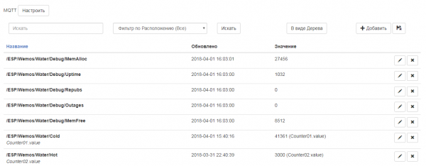
These values can now be linked with system objects, used in automation scenarios, and subjected to various analyses—all of this is out of scope for this article. For those interested in the Majordomo system, I can recommend — a friend is also building a smart home and explains system setup clearly.
I'll show just a couple of graphs. This is a simple daily value graph.
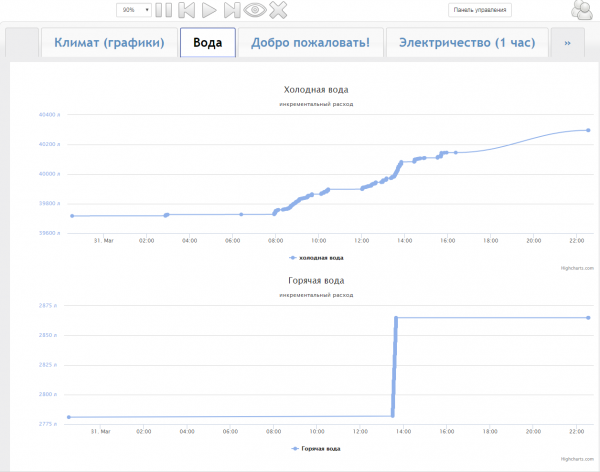
You can see that hardly anyone used water at night. A few times someone went to the restroom, and it seems like the reverse osmosis filter sucks up a couple of liters overnight. In the morning, consumption significantly increases. Usually, I use water from the boiler, but here I wanted to take a bath and temporarily switched to city hot water—this is also clearly visible in the lower graph.
From this graph, I learned that going to the bathroom uses 6-7 liters of water, taking a shower uses 20-30 liters, washing dishes takes about 20 liters, and taking a bath requires 160 liters. My family consumes around 500-600 liters a day.
For the particularly curious, you can check the records for each individual value.
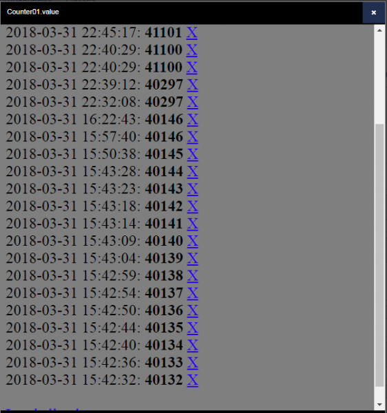
From here, I found out that when the tap is open, water flows at a rate of approximately 1 liter per 5 seconds.
However, in this form, the statistics aren’t very convenient to look at. In Majordomo, there are also options to view consumption graphs by days, weeks, and months. For example, here is a bar chart of consumption.
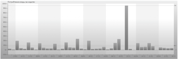
So far, I only have data for a week. In a month, this graph will be more informative—each day will correspond to a separate bar. The adjustments I make manually (the biggest bar) slightly spoil the picture. It's unclear whether I set the initial values almost a cubic meter lower incorrectly, or if it's a bug in the firmware and not all liters are being accounted for. More time is needed.
The graphs themselves still need some tweaking, polishing, and coloring. I might also consider building a memory consumption graph for debugging purposes—perhaps there’s some leak. I might display periods when the internet was unavailable somehow. For now, everything is still at the idea stage.
Conclusion
Today, my apartment became a little smarter. With this small device, it will be easier for me to monitor water consumption in the house. If before I often complained, “we used too much water this month,” now I can find the source of that consumption.
Some may find it strange to view readings on the screen when it's just a meter away from the meter itself. But in the not-so-distant future, I plan to move to another apartment, where there will be several water risers, and the meters will likely be located on the staircase landing. So, a remote reading device will definitely come in handy.
I also plan to expand the device's functionality. I'm already looking into motorized valves. Currently, to switch between the boiler and city water, I need to turn 3 taps in a hard-to-reach niche. It would be much more convenient to do this with the push of a button with appropriate indication. And, of course, it’s worth implementing leak protection.
In this article, I shared my version of a device based on the ESP8266. In my opinion, I developed a rather interesting firmware variant on MicroPython using coroutines — simple and attractive. I tried to describe many nuances and pitfalls I encountered along the way. Perhaps I detailed everything too much; personally, I find it easier to skip unnecessary parts than to guess what was left unsaid.
As always, I am open to constructive criticism.
Source: habr.com
