

Introduction
The concept of building a 'Digital Substation' in the electricity sector requires synchronization with an accuracy of 1 microsecond. Financial transactions also require accuracy within microseconds. In these applications, the time accuracy of NTP is no longer sufficient.
The PTPv2 synchronization protocol, described by the IEEE 1588v2 standard, allows for synchronization accuracy within several tens of nanoseconds. PTPv2 enables the sending of synchronization packets over L2 and L3 networks.
The main areas where PTPv2 is applied include:
- energy sector;
- measuring equipment;
- defense industry;
- telecom;
- financial sector.
This post discusses how the PTPv2 synchronization protocol works.
We have more industry experience and often encounter this protocol in energy applications. Therefore, we will approach the overview with a focus on .
Why is it necessary?
Currently, the STO 34.01-21-004-2019 of PJSC 'Rosseti' and the STO 56947007-29.240.10.302-2020 of PJSC 'FSK EES' contain requirements for the organization of the process bus with time synchronization provided by PTPv2.
This is related to the fact that relaying protection terminals and measuring devices connect to the process bus, which transmits instantaneous values of current and voltage through the process bus using so-called SV streams (multicast streams).
Relay protection terminals use these values to implement the protection of connections. If the timing of measurements is inaccurate, some protections may trigger falsely.
For example, protections of absolute selectivity can fall victim to 'weak' time synchronization. Often, the logic of such protections is based on comparing two values. If the values diverge significantly, the protection is activated. If these values are measured with an accuracy of 1 ms, a large difference may appear where the values are actually normal when measured with an accuracy of 1 µs.
PTP Versions
The PTP protocol was originally described in 2002 in the IEEE 1588-2002 standard, titled 'Standard for a Precision Clock Synchronization Protocol for Networked Measurement and Control Systems.' In 2008, an updated standard, IEEE 1588-2008, was released, which describes PTP Version 2. This version of the protocol improved accuracy and stability, but did not maintain backward compatibility with the first version. Additionally, in 2019, the IEEE 1588-2019 version was released, describing PTP v2.1. This version adds minor enhancements to PTPv2 and is backward compatible with PTPv2.
In other words, we have the following picture with versions:
PTPv1
(IEEE 1588-2002)
PTPv2
(IEEE 1588-2008)
PTPv2.1
(IEEE 1588-2019)
PTPv1 (IEEE 1588-2002)
—
Incompatible
Incompatible
PTPv2 (IEEE 1588-2008)
Incompatible
—
Compatible
PTPv2.1 (IEEE 1588-2019)
Incompatible
Compatible
—
But, as always, there are nuances.
Incompatibility between PTPv1 and PTPv2 implies that a device supporting PTPv1 will not be able to synchronize from precision clocks operating on PTPv2. They use different message formats for synchronization.
However, it is still possible to connect PTPv1 devices and PTPv2 devices in the same network. Some manufacturers allow the selection of protocol versions on boundary clock ports. This means that boundary clocks can synchronize using PTPv2 while synchronizing other connected clocks using both PTPv1 and PTPv2.
PTP Devices. What types are there and how do they differ?
The IEEE 1588v2 standard describes several types of devices. All of them are listed in the table.
Devices interact with each other over a LAN using PTP.
PTP devices are called clocks. All clocks derive precise time from grandmaster clocks.
There are 5 types of clocks:
Grandmaster clock
The primary source of precise time. Often equipped with a GPS connection interface.
Ordinary Clock
A device with one port that can be a master (leading clock) or a slave (following clock).
Master clock
Serves as the source of precise time from which other clocks synchronize.
Slave clock
An end device that synchronizes with master clocks.
Boundary Clock
A device with multiple ports that can be a master or slave.
This means these clocks can synchronize from upstream master clocks and synchronize downstream slave clocks.
End-to-end Transparent Clock
A multi-port device that is neither a master clock nor a slave clock. It transmits PTP data between two clocks.
When transmitting data, transparent clocks adjust all PTP messages.
The adjustment is made by adding a delay time to this device in the correction field of the transmitted message header.
Peer-to-Peer Transparent Clock
A multi-port device that is neither a master clock nor a slave clock.
It transmits PTP data between two clocks.
When transmitting data, transparent clocks adjust all Sync and Follow_Up PTP messages (which are discussed in more detail below).
The adjustment is achieved by adding the delay at the transmitting device to the correction field of the transmitted packet and the delay in the data transmission channel.
Management Node
A device that configures and diagnoses other clocks.
Master and slave clocks synchronize using timestamps in PTP messages. There are two types of messages in the PTP protocol:
- Event Messages are synchronized messages that allow timestamp generation at the moment of sending and receiving the message.
- General Messages do not require timestamps but may contain timestamps for related messages.
Event Messages
General Messages
Sync
Delay_Req
Pdelay_Req
Pdelay_Resp
Announce
Follow_Up
Delay_Resp
Pdelay_Resp_Follow_Up
Management
Signaling
All message types will be discussed in more detail below.
Key Synchronization Issues
When transmitting a sync packet over a local network, it is delayed at the switch and in the data transmission channel. Any switch will introduce a delay of about 10 microseconds, which is unacceptable for PTPv2. We need to achieve 1 microsecond accuracy at the end device. (This is if we're talking about power applications. Other applications may require even greater precision.)
IEEE 1588v2 describes several operating algorithms that allow for time delay measurement and correction.
Operating Algorithm
Under normal operation, the protocol works in two phases.
- Phase 1 — establishing the hierarchy of Master Clock – Slave Clock.
- Phase 2 — synchronizing clocks using either the End-to-End or Peer-to-Peer mechanism.
Phase 1 - Master-Slave Hierarchy Setup
Each port of ordinary or boundary clocks has a specific number of states (slave clocks and master clocks). The standard describes the algorithm for transitioning between these states. In programming, such an algorithm is called a finite state machine (see more in Wiki).
This finite state machine uses the Best Master Clock Algorithm (BMCA) to establish the master when connecting two clocks.
This algorithm allows clocks to take on the commitments of grandmaster clocks when the higher-level grandmaster clocks lose their GPS signal, disconnect from the network, etc.
State transitions according to BMCA are briefly depicted in the following diagram:
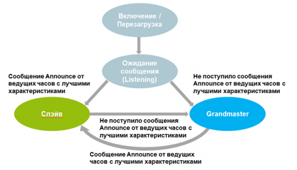
Information about the clock on the other end of the 'wire' is sent in a special message (Announce message). When this information is received, the state machine algorithm processes it and compares which clock is better. The port on the better clock becomes the master clock.
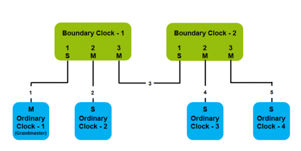
A simple hierarchy is represented in the diagram below. Paths 1, 2, 3, 4, 5 may contain transparent clocks but do not participate in establishing the 'Master-Slave' hierarchy.
Phase 2 - Synchronization of Ordinary and Boundary Clocks
Immediately after establishing the 'Master-Slave' hierarchy, the synchronization phase of ordinary and boundary clocks begins.
To synchronize, the master clock sends a message containing a timestamp to the slave clocks.
Master clocks can be:
- one-step;
- two-step.
One-step clocks send a single Sync message for synchronization.
Two-step clocks use two messages for synchronization - Sync and Follow_Up.
Two mechanisms can be used for the synchronization phase:
- Delay request-response mechanism.
- Peer delay measurement mechanism.
Let's first consider these mechanisms in the simplest case - when transparent clocks are not used.
Delay request-response mechanism
The mechanism involves two steps:
- Measuring the delay when transmitting a message between the master and slave clocks. This is done using the delay request-response mechanism.
- A correction of the precise time offset is carried out.
Delay measurement

t1 – Sending time of the Sync message by the master clock; t2 – Receiving time of the Sync message by the slave clock; t3 – Sending time of the Delay_Req request by the slave clock; t4 – Receiving time of the Delay_Req by the master clock.
When the slave clock knows the times t1, t2, t3, and t4, it can calculate the average delay in the transmission of the synchronization message (tmpd). It is calculated as follows:
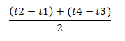
When transmitting the Sync and Follow_Up messages, the time delay from the master to the slave is calculated – t-ms.
When transmitting Delay_Req and Delay_Resp messages, the time delay from the slave to the master is calculated – t-sm.
If there is any asymmetry between these two values, an error in the precise time correction occurs. The error is due to the fact that the calculated delay is an average of the delays t-ms and t-sm. If the delays are not equal to each other, we will adjust the time inaccurately.
Correction of precise time shift
Once the delay between the master and slave clocks is known, the slave clock performs a time correction.
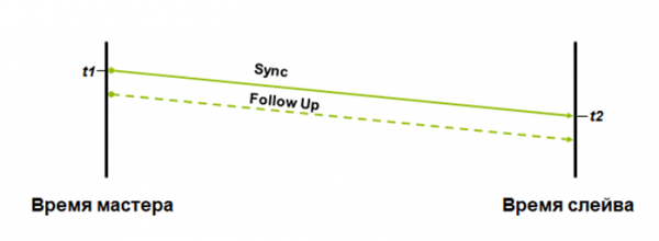
The slave clock uses the Sync message and an optional Follow_Up message to calculate the precise time shift during packet transmission from the master clock to the slave. The shift is calculated using the following formula:
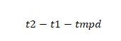
Peer Delay Measurement Mechanism
This mechanism also uses two steps for synchronization:
- Devices measure the time delay to all neighbors through all ports. For this, they use the peer delay mechanism.
- Correction of precise time shift.
Measurement of delay between devices supporting Peer-to-Peer mode
The delay between ports that support the peer-to-peer mechanism is measured using the following messages:
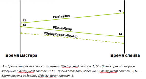
When port 1 knows the times t1, t2, t3, and t4, it can calculate the average delay (tmld). It is calculated using the following formula:
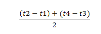
The port then uses this value when calculating the correction field for each Sync message or optional Follow_Up message that passes through this device.
The total delay will be equal to the sum of the delay during the transmission through this device, the average delay during the transmission through the data channel, and the already contained delay in this message, included on the upstream devices.
The Pdelay_Req, Pdelay_Resp, and optional Pdelay_Resp_Follow_Up messages allow for measuring the delay from the master to the slave and from the slave to the master (round trip).
Any asymmetry between these two values will introduce a time offset correction error.
Time offset correction
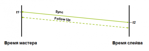
Slave clocks use the Sync message and the optional Follow_Up message to calculate the time offset when a packet is transmitted from the master clocks to the slave clocks. The offset is calculated using the following formula:

The advantages of the peer-to-peer correction mechanism include that the delay of each Sync or Follow_Up message is calculated during its transmission across the network. Consequently, changes in the transmission path will not affect the accuracy of the correction.
When using this mechanism, time synchronization does not require calculating the delay of the path taken by the synchronization packet, as is done in basic exchanges. That is, Delay_Req and Delay_Resp messages are not sent. In this method, the delay between the master and slave clocks is simply summed in the correction field of each Sync or Follow_Up message.
Another advantage is that master clocks are relieved from the need to process Delay_Req messages.
Operating modes of transparent clocks
Accordingly, simple examples have been discussed. Now, let's assume that switches appear on the synchronization path.
If switches that do not support PTPv2 are used, the synchronization packet will be delayed on the switch by approximately 10 µs.
Switches that support PTPv2 are referred to as transparent clocks in IEEE 1588v2 terminology. Transparent clocks do not synchronize from the master clocks and do not participate in the hierarchy of 'Master clocks – Slave clocks', but they record how much a synchronization message has been delayed while passing through them. This allows for adjusting the time delay.
Transparent clocks can operate in two modes:
- End-to-End.
- Peer-to-Peer.
End-to-End (E2E)
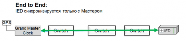
E2E transparent clocks transmit Sync messages and corresponding Follow_Up messages to all ports, even those blocked by certain protocols (such as RSTP).
The switch records the timestamp when a Sync (Follow_Up) packet is received at a port and when it is sent from the port. Based on these two timestamps, the processing time for the message by the switch is calculated. In the standard, this time is referred to as residence time.
The processing time is added to the correctionField of the Sync message (one-step clocks) or Follow_Up (two-step clocks).
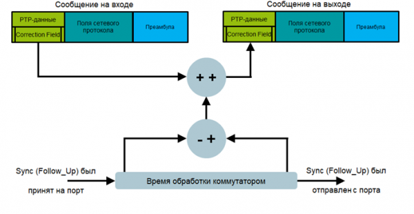
End-to-end transparent clocks measure processing time for Sync and Delay_Req messages passing through the switch. However, it is important to understand that the delay between the master and slave clocks is calculated using the delay request-response mechanism. If the master clocks change or the path from the master clocks to the slaves changes, the delay is measured anew. This increases the transitional state time in case of network changes.
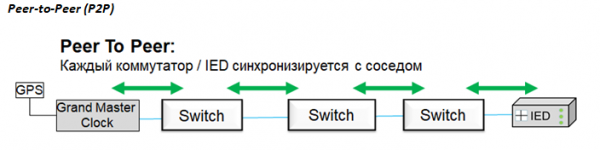
Peer-to-peer transparent clocks, in addition to measuring the processing time of messages by the switch, measure the delay on the data link to the nearest neighbor using the neighboring node's delay measurement mechanism.
The delay is measured on each link in both directions, including links that are blocked by any protocol (e.g., RSTP). This allows the new delay on the synchronization path to be immediately calculated if the grandmaster clocks or network topology change.
The processing times of messages by switches and the delay times are accumulated during the transmission of Sync or Follow_Up messages.
Types of PTPv2 Support by Switches
Switches can support PTPv2:
- in software;
- in hardware.
In the software implementation of the PTPv2 protocol, the switch requests a timestamp from the firmware. The issue is that the firmware operates cyclically, and one must wait until it completes the current cycle, processes the request, and issues the timestamp at the end of the next cycle. This will also take time, resulting in a delay, albeit not as significant as without software support for PTPv2.
Only hardware support for PTPv2 can provide the necessary accuracy. In this case, the timestamp is issued by a special ASIC installed on the port.
Message Format
All PTP messages consist of the following fields:
- Header – 34 bytes.
- Body – size depends on the message type.
- Suffix – optional.
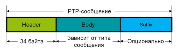
Header
The Header field is the same for all PTP messages. Its size is 34 bytes.
Header field format:
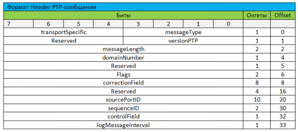
messageType – contains the type of the transmitted message, such as Sync, Delay_Req, PDelay_Req, etc.
messageLength – contains the total size of the PTP message, including the header, body, and suffix (but excluding padding bytes).
domainNumber – defines which domain PTP the message belongs to.
Domain – is a collection of multiple clocks grouped into a single logical entity and synchronized from one master clock, but not necessarily synchronized with clocks belonging to another domain.
flags – this field contains various flags to identify the status of the message.
correctionField – contains the delay time in nanoseconds. The delay time includes the delay incurred when passing through transparent clocks, as well as the delay during transmission through the channel when using Peer-to-Peer mode.
sourcePortIdentity – this field contains information about which port the message was originally sent from.
sequenceID – contains an identification number for individual messages.
controlField – an artifact field =) It remains from the first version of the standard and contains information about the type of this message. Essentially, it is the same as messageType, but with fewer options.
logMessageInterval – this field is defined by the type of message.
Body
As discussed above, there are several types of messages. These types are described below:
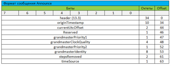
Announce Message
The Announce message is used to 'tell' other clocks within the same domain about its parameters. This message allows establishing a hierarchy of 'Master Clock – Slave Clocks'.
Sync Message
The Sync message is sent by the master clocks and contains the time of the master clocks at the moment when the Sync message was created. If the master clocks are two-step, the timestamp in the Sync message will be set to 0, and the actual timestamp will be sent in the accompanying Follow_Up message. The Sync message is used for both delay measurement mechanisms.
The message is transmitted via Multicast. Optionally, Unicast can be used.

Delay_Req Message
The format of the Delay_Req message is identical to that of the Sync message. Slave clocks send Delay_Req. It contains the time of sending Delay_Req by the slave clocks. This message is used solely for the request-response delay mechanism.
The message is transmitted via Multicast. Optionally, Unicast can be used.

Follow_Up Message
The Follow_Up message is optionally sent by the primary clocks and contains the send time. Sync messages by the master. The Follow_Up message is sent only by two-step primary clocks.
The Follow_Up message is used for both delay measurement mechanisms.
The message is transmitted via Multicast. Optionally, Unicast can be used.

Delay_Resp Message
The Delay_Resp message is sent by the primary clocks. It contains the reception time of the Delay_Req by the primary clocks. This message is used only for the delay request-response mechanism.
The message is transmitted via Multicast. Optionally, Unicast can be used.

Pdelay_Req Message
The Pdelay_Req message is sent by the device that requests delay. It contains the send time of the message from the port of this device. Pdelay_Req is used only for the adjacent node delay measurement mechanism.

Pdelay_Resp Message
The Pdelay_Resp message is sent by the device that received the delay request. It contains the reception time of the Pdelay_Req message by this device. The Pdelay_Resp messages are used only for the adjacent node delay measurement mechanism.

Pdelay_Resp_Follow_Up Message
The Pdelay_Resp_Follow_Up message is optionally sent by the device that received the delay request. It contains the reception time of the Pdelay_Req message by this device. The Pdelay_Resp_Follow_Up message is sent only by two-step primary clocks.
This message can also be used for execution time instead of a timestamp. Execution time is the time from when Pdelay-Req is received to when Pdelay_Resp is sent.
Pdelay_Resp_Follow_Up messages are used only for the adjacent node delay measurement mechanism.

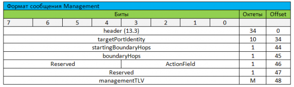
Management Messages
PTP management messages are necessary for transmitting information between one or several clocks and the management node.
Transmission in LV
PTP messages can be transmitted at two levels:
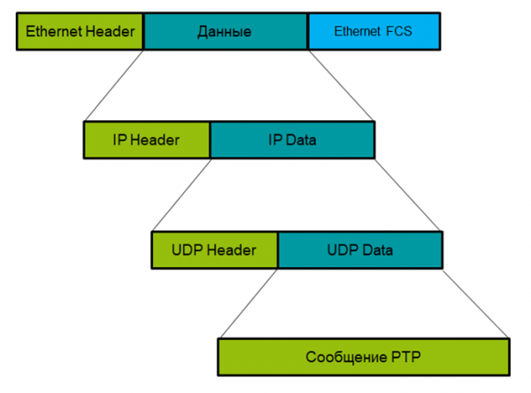
- Network – as part of IP data.
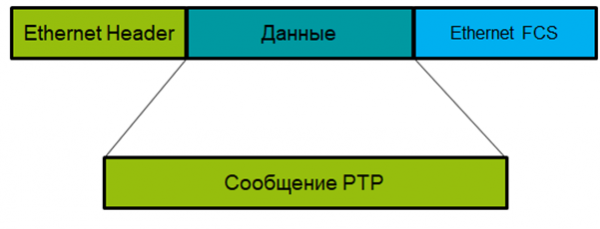
- Link – as part of an Ethernet frame.
Transmission of PTP messages via UDP over IP over Ethernet
PTP via UDP over Ethernet
Profiles
PTP has quite a few 'flexible' parameters that need to be configured. For example:
- BMCA options.
- Delay measurement mechanism.
- Intervals and initial values of all configurable parameters, etc.
And despite what was previously stated about PTPv2 devices being compatible with each other, this is not entirely true. Devices must have the same settings to interact.
This is why there are so-called PTPv2 profiles. Profiles are groups of configured settings and defined protocol constraints to enable time synchronization for a specific application.
The IEEE 1588v2 standard describes only one profile – the ‘Default Profile’. All other profiles are created and described by various organizations and associations.
For example, the profile for power systems or the PTPv2 Power Profile was created by the Power Systems Relaying Committee and the Substation Committee of the IEEE Power and Energy Society. The profile is titled IEEE C37.238-2011.
The profile describes that PTP can be transmitted:
- Only through L2 networks (i.e., Ethernet, HSR, PRP, not IP).
- Messages are transmitted only via Multicast.
- The Peer delay measurement mechanism is used as a delay measurement method.
The default domain is 0, while the recommended domain is 93.
The philosophy behind C37.238-2011 aimed to reduce the number of optional features and retain only the necessary functions for reliable device interaction and system stability.
Additionally, the frequency of message transmission is defined:
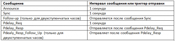
In essence, there is only one parameter available for selection – the type of master clock (single-stage or two-stage).
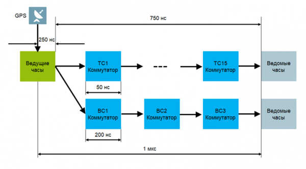
Accuracy must not exceed 1 microsecond. In other words, a single synchronization path may contain a maximum of 15 transparent clocks or three boundary clocks.
Source: habr.com
