

Despite the widespread adoption of Ethernet networks, DSL-based communication technologies remain relevant to this day. DSL can still be found in last-mile networks for connecting subscriber equipment to Internet service providers, and recently the technology is increasingly used in local networks, for example, in industrial applications where DSL complements Ethernet or field networks based on RS-232/422/485. Such industrial solutions are actively applied in developed European and Asian countries.
DSL represents a family of standards originally designed for transmitting digital data over telephone communication lines. Historically, it became the first broadband access technology to the Internet, replacing Dial-Up and ISDN. The variety of existing DSL standards today is due to many companies, starting from the 1980s, striving to develop and promote their own technology in the market.
All these developments can be divided into two major categories – asymmetric (ADSL) and symmetric (SDSL) technologies. Asymmetric technologies are those where the speed of the incoming connection differs from the outgoing traffic speed. Symmetric technologies mean that the speeds for receiving and transmitting are equal.
The most well-known and widespread asymmetric standards are, in fact, ADSL (in its latest version – ADSL2+) and VDSL (VDSL2), while symmetric standards include HDSL (an outdated profile) and SHDSL. They differ from each other by operating on different frequencies, utilizing different encoding and modulation methods on the physical communication line. Error correction methods also vary, which provides different levels of noise immunity. As a result, each technology has its own limits in speed and distance for data transmission, depending on the type and quality of the conductor.
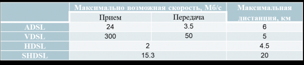
Limit parameters of various DSL standards
In any DSL technology, data transfer speed decreases as the length of the conductor increases. At extreme distances, speeds of several hundred kilobits can be achieved, but at distances of 200-300 meters, the maximum possible speed is available.
Among all technologies, SHDSL has a significant advantage that allows it to be used in industrial applications – high resistance to interference and the ability to use any type of conductor for data transmission. Asymmetric standards do not offer this, and the quality of communication heavily depends on the quality of the line used for data transfer. In particular, twisted telephone cables are recommended. In this case, using optical cables is a more reliable solution than ADSL and VDSL.
Any pair of insulated conductors is suitable for SHDSL – copper, aluminum, steel, etc. Old electrical wiring, old telephone lines, barbed wire fences, and so forth can serve as the transmission medium.
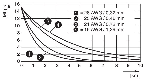
The dependence of SHDSL data transfer speed on distance and type of conductor
From the graph showing the dependence of data transfer speed on distance and type of conductor for SHDSL, it can be seen that conductors with a larger cross-section allow for transmitting information over greater distances. Thanks to this technology, it is possible to establish communication over distances of up to 20 km with a maximum speed of 15.3 Mb/s for a 2-wire cable or 30 Mb for a 4-wire cable. In real applications, the transfer speed can be manually adjusted, which is necessary in conditions of strong electromagnetic interference or poor line quality. In this case, to increase the transmission distance, it is necessary to reduce the speed of the SHDSL devices. Free software tools, such as .
What gives SHDSL its high resistance to interference?
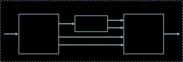
The principle of operation of the SHDSL transceiver can be represented in a block diagram, which highlights a specific and independent (invariant) part from the application's perspective. The independent part consists of functional blocks PMD (Physical Medium Dependent) and PMS-TC (Physical Medium-Specific TC Layer), while the specific part includes the TPS-TC (Transmission Protocol-Specific TC Layer) and user data interfaces.
The physical communication line between transceivers (STU) can exist as a single twisted pair or multiple twisted pairs of cables. In the case of multiple pairs of cables, the STU contains several independent PMD blocks connected to a single PMS-TC.
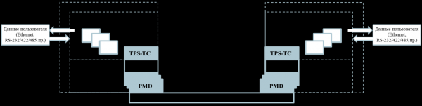
Functional model of the SHDSL transceiver (STU)
The TPS-TC module depends on the application in which the device is used (Ethernet, RS-232/422/485, etc.). Its task is to convert user data into SHDSL format, performing multiplexing/demultiplexing and timing adjustment of multiple user data channels.
At the PMS-TC level, SHDSL frames are formed and synchronized, as well as scrambling and descrambling.
The PMD module performs the functions of encoding/decoding information, modulation/demodulation, echo cancellation, parameter matching on the communication line, and establishing connections between transceivers. It is at the PMD level that the main operations ensuring high interference resistance of SHDSL are carried out, including TCPAM encoding (Trellis coding with pulse amplitude modulation), a joint coding and modulation mechanism that improves the spectral efficiency of the signal compared to separate methods. The principle of operation of the PMD module can also be represented in the form of a functional diagram.
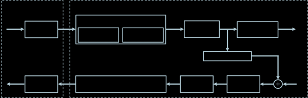
Block diagram of the PMD module
At the core of TC-PAM is the use of a convolutional encoder that generates a redundant bit sequence on the SHDSL transmitter side. During each operational clock cycle, each bit entering the encoder corresponds to a double bit (dibit) at the output. Thus, with relatively low redundancy, the resilience of transmission against interference is increased. The use of Trellis modulation allows reducing the bandwidth used for data transmission and simplifies the hardware while maintaining the same signal-to-noise ratio.
Operating Principle of the Trellis Encoder (TC-PAM 16)
The double bit is formed as a result of a logical operation of addition modulo 2 (exclusive 'or') based on the input bit x1(tn) and the bits x1(tn-1), x1(tn-2), etc. (there can be up to 20 of them), which were fed into the encoder earlier and remain stored in memory registers. In the next clock cycle of the encoder tn+1, a shift of bits in the memory cells will occur to perform the logical operation: the bit x1(tn) will move to memory, shifting the entire stored sequence of bits.
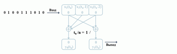
Algorithm of the Convolutional Encoder
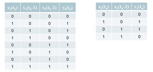
Truth Tables for Addition Modulo 2
For clarity, it is convenient to use a state diagram of the convolutional encoder, which shows the state of the encoder at moments tn, tn+1, etc., depending on the input data. The state of the encoder in this case implies a pair of values consisting of the input bit x1(tn) and the bit in the first memory cell x1(tn-1). To construct the diagram, a graph can be used where the vertices represent possible states of the encoder and the transitions from one state to another are marked with the corresponding input bits x1(tn) and output dibits $inline$y ₀y ₁(t ₀)$inline$.
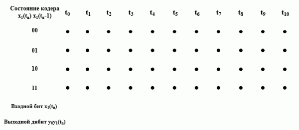
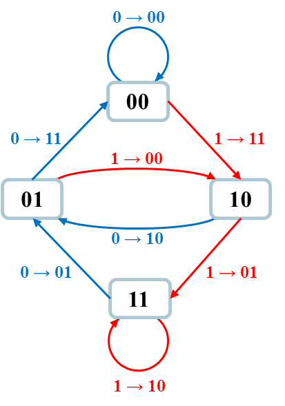
State Diagram and Transition Graph of the Convolutional Encoder Transmitter
In the transmitter, based on the received four bits (two output bits of the encoder and two data bits), a symbol is formed, each of which corresponds to a specific amplitude of the modulating signal of the analog-pulse modulator.
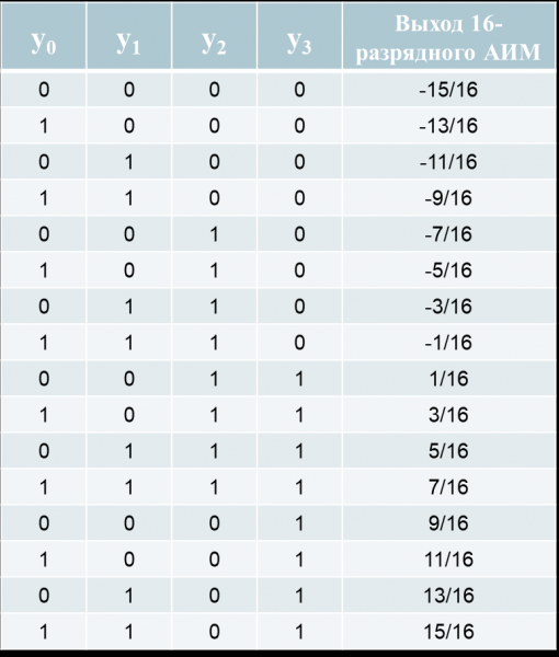
State of the 16-bit APM Depending on the Value of the Four-bit Symbol
On the signal receiver side, the reverse process occurs – demodulation and extraction of the required sequence of input bits from the redundant code (double bits y0y1(tn)) of the encoder x1(tn). This operation is performed by the Viterbi decoder.
The decoder algorithm is based on calculating the error metric for all possible assumed states of the encoder. The error metric refers to the difference between the received bits and the assumed bits for each possible path. If there are no errors upon reception, the error metric of the true path will be 0, because there is no bit mismatch. For false paths, the metric will differ from zero, continually increase, and after some time, the decoder will stop calculating the erroneous path, leaving only the true one.
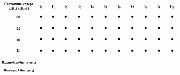
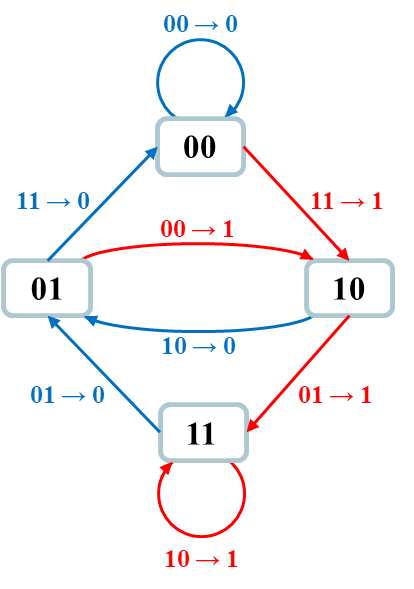
State diagram of the encoder computed by the receiver's Viterbi decoder
But how does this algorithm ensure noise immunity? If we assume that the receiver received data with an error, the decoder will continue calculating two paths with an error metric of 1. The path with a metric of 0 will no longer exist. However, the algorithm will determine which path is true later based on the following received double bits.
When a second error occurs, there will be several paths with a metric of 2, but the correct path will be identified later based on the maximum likelihood method (i.e., the minimum metric).
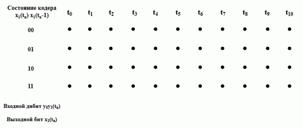
State diagram of the encoder computed by the Viterbi decoder upon receiving erroneous data
In the example described above, a 16-bit system algorithm (TC-PAM16) was considered, providing the transmission of three bits of useful information and an additional bit for error protection in one symbol. In TC-PAM16, data transmission speeds range from 192 to 3840 kbit/s. When increasing the bit depth to 128 (modern systems operate with TC-PAM128), six bits of useful information are transmitted in each symbol, with maximum achievable speeds ranging from 5696 kbit/s to 15.3 Mb/s.
The use of pulse amplitude modulation (PAM) connects SHDSL with a number of popular Ethernet standards, such as Gigabit 1000BASE-T (PAM-5), 10-Gigabit 10GBASE-T (PAM-16), or the promising 2020 industrial single-pair Ethernet 10BASE-T1L (PAM-3).
SHDSL in Ethernet networks
Managed and unmanaged SHDSL modems are distinguished, but this classification has little in common with the familiar division into managed and unmanaged devices, such as those used for Ethernet switches. The difference lies in the means of configuration and monitoring. Managed modems are set up via a web interface and can be diagnosed through SNMP, while unmanaged ones require additional software through a console port (for Phoenix Contact, this is the free PSI-CONF program and mini-USB interface). Unlike switches, unmanaged modems can operate in a ring topology network.
Otherwise, managed and unmanaged modems are absolutely identical, including functionality and the ability to work on a Plug & Play basis, meaning no prior configuration is needed.
Additionally, modems may be tasked with surge protection functions with diagnostic capabilities. SHDSL networks can form very long segments, and conductors may run in areas where surge events can occur (induced voltage differences caused by lightning strikes or short circuits in nearby cable lines). Induced voltage can lead to discharge currents reaching kiloamperes. Therefore, to protect equipment from such phenomena, modems are equipped with surge protective devices in the form of removable boards, which can be replaced if necessary. The SHDSL line is connected to the terminal block of this board.
Topologies
With SHDSL, it is possible to build Ethernet networks with any topology: point-to-point, line, star, and ring. Depending on the type of modem, both 2-wire and 4-wire communication lines can be used for connections.
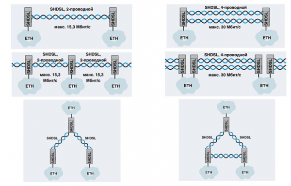
Ethernet network topologies based on SHDSL
Distributed systems with a combined topology can also be built. Each segment of the SHDSL network can consist of up to 50 modems, and given the physical capabilities of the technology (distance between modems up to 20 km), the length of a segment can reach 1000 km.
If a managed modem is installed in the head of each such segment, the integrity of the segment can be diagnosed via SNMP. In addition, both managed and unmanaged modems support VLAN technology, which allows the network to be divided into logical subnets. Moreover, the devices are capable of working with data transfer protocols used in modern automation systems (Profinet, Ethernet/IP, Modbus TCP, etc.).
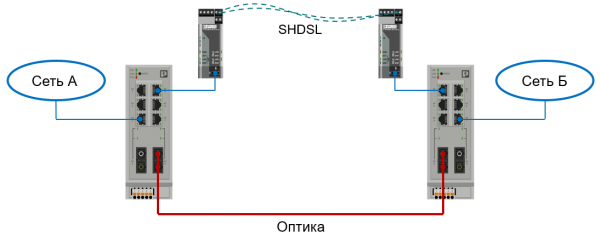
Redundancy of communication channels using SHDSL
SHDSL is used to create backup communication channels in Ethernet networks, most often optical.
SHDSL and serial interface
SHDSL modems with a serial interface allow overcoming the limitations of distance, topology, and conductor quality that exist in traditional wired systems based on asynchronous transmitters (UART): RS-232 — 15 m, RS-422 and RS-485 — 1200 m.
There are modems with serial interfaces (RS-232/422/485) for both universal applications and specialized ones (for example, for Profibus). All such devices fall into the category of 'unmanaged' devices, so they are configured and diagnosed using specialized software.
Topologies
In networks with a serial interface, SHDSL allows constructing networks with point-to-point, line, and star topologies. In a linear topology, it's possible to combine up to 255 nodes into one network (30 for Profibus).
In systems built using only devices with the RS-485 interface, there are no restrictions on the data transfer protocols used, but line and star topologies are atypical for RS-232 and RS-422. Therefore, the operation of end devices in an SHDSL network with such topologies is only possible in half-duplex mode. Simultaneously, in systems with RS-232 and RS-422, device addressing at the protocol level must be ensured, which is not typical for interfaces usually used in point-to-point networks.
When connecting devices with different types of interfaces through SHDSL, it's necessary to take into account the lack of a unified mechanism for establishing a connection (handshake) between devices. However, organizing communication in this case is still possible—this requires fulfilling the following conditions:
- The coordination of communication and data transmission management must be performed at the level of a unified data transmission protocol;
- all end devices should operate in half-duplex mode, which must also be supported by the information protocol.
The most commonly used protocol for asynchronous interfaces, Modbus RTU, allows for overcoming all the described limitations and building a unified system with various types of interfaces.
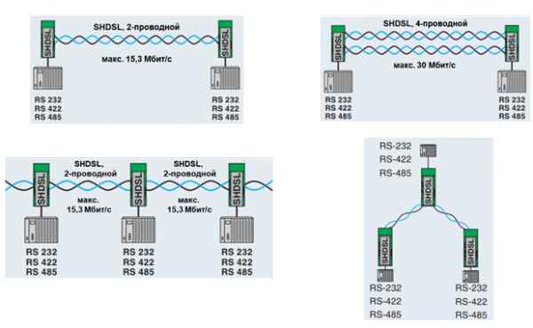
Network topologies with a serial interface based on SHDSL
When using two-wire RS-485 on equipment more complex structures can be built by connecting modems via a single bus on a DIN rail. On this same bus, a power supply can be installed (in this case, all devices receive power through the bus) and optical converters of the PSI-MOS series can be used to create a combined network. An important condition for the operation of such a system is that all transceivers must operate at the same speed.
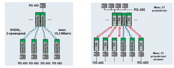
Additional capabilities of SHDSL in the RS-485 network
Application examples
SHDSL technology is actively used in urban utilities in Germany. Over 50 companies servicing municipal systems utilize old copper wires to connect distributed facilities across the city into a single network. SHDSL is primarily used for management and accounting systems in water, gas, and energy supply. Cities such as Ulm, Magdeburg, Ingolstadt, Bielefeld, Frankfurt (Oder), and many others are included.
The largest system based on SHDSL was created in the city of Lübeck. The system has a combined structure based on optical Ethernet and SHDSL, integrating 120 remote facilities and utilizing over 50 modems. The entire network is diagnosed via SNMP. The longest segment from the municipality of Kalkhorst to Lübeck Airport spans 39 km. The reason the client company chose SHDSL was that implementing the project entirely with fiber optics was economically unfeasible given the existence of old copper cables.
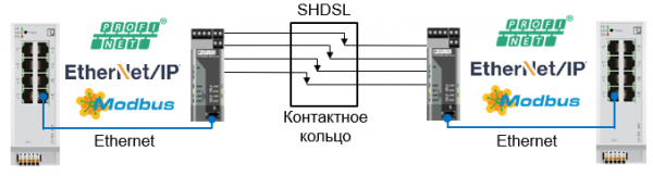
Data transmission through the contact ring
An interesting example is the transmission of data between moving objects, as seen in wind turbines or large industrial torque machines. Such systems are used for information exchange between controllers located on the rotor and stator of the installations. In this case, data is transmitted using a sliding contact through a contact ring. These examples show that a static contact is not necessary for data transmission via SHDSL.
Comparison with Other Technologies
SHDSL vs GSM
When comparing SHDSL to data transmission systems based on GSM (3G/4G), the advantages of DSL include the absence of operational costs associated with regular payments to the operator for access to the mobile network. With SHDSL, we are not dependent on coverage, the quality and reliability of mobile communication at the industrial site, including resistance to electromagnetic interference. SHDSL eliminates the need for equipment configuration, which speeds up commissioning. Wireless networks are characterized by high data transmission delays and complications in handling multicast traffic (Profinet, Ethernet IP).
The information security of SHDSL is a significant advantage due to the lack of need to transmit data over the Internet and the requirement for VPN configurations.
SHDSL vs Wi-Fi
Much of what has been said about GSM can also be applied to industrial Wi-Fi. The disadvantages of Wi-Fi include low noise immunity, limited data transmission distance, dependence on terrain topology, and data transmission delays. The main disadvantage is the information security of Wi-Fi networks, as anyone can access the transmission medium. It is already possible to transmit Profinet or Ethernet IP data using Wi-Fi, which would be difficult for GSM.
SHDSL vs Optical
Optical technology generally has a significant advantage over SHDSL, but in some applications, SHDSL can save time and resources on laying and welding optical cables, thus reducing the time required to put the facility into operation. SHDSL does not require special connectors, as the communication cable simply connects to the modem's terminal. Due to the mechanical properties of optical cables, their use is limited in applications related to data transmission between moving objects, where copper conductors are more widely used.
Source: habr.com
