

During the quarantine, I was offered to participate in the development of a device for measuring the speed of LTE modems for several cellular operators.
The client wanted to evaluate the speed of various service providers at different geographical locations to understand which cellular operator would be most optimal for installing equipment that uses LTE connections, such as for video broadcasts. The task needed to be solved as simply and cheaply as possible, without expensive equipment.
I should mention that this task is quite complex and research-intensive; I will describe the problems I encountered and how I resolved them. Let's get started.
Note
Measuring the speed of an LTE connection is a rather complicated matter: it is necessary to correctly choose the equipment and the measurement methodology while being well aware of the topology and functioning of the cellular network. Additionally, several factors can affect speed: the number of subscribers on a cell, weather conditions, and even the speed can vary significantly from cell to cell due to network topology. Overall, this task has a vast number of unknowns, and only a service provider can solve it correctly.
Initially, the client wanted to simply have a courier test the phones of the operators, conducting measurements directly on the phone and then noting the speed measurement results in a notebook. My solution for measuring LTE network speeds, though not perfect, addresses the task at hand.
Due to time constraints, I made decisions more in favor of speed of development rather than convenience or practicality. For example, I set up reverse SSH for remote access instead of a more practical VPN to save time on server configuration and each individual client.
Technical specifications
As mentioned in the article : Don't work without a technical specification! Never, anywhere!
The technical specification was quite simple; I will elaborate a bit for the end-user's understanding. The choice of technical solutions and equipment was dictated by the client. So here's the technical specification after all agreements:
Based on a single-board computer vim2 create an LTE connection speed tester using Huawei e3372h — 153 several service providers (from one to n). It is also necessary to obtain coordinates from a GPS receiver connected via UART. Speed measurements should be made using the service and compile them into a table format:
Table in csv format. After that, send this table via e-mail every 6 hours. In case of errors, a LED connected to GPIO should blink.

I described the specifications informally, after many approvals. But the essence of the task is already clear. The timeframe was set for a week for everything. But in reality, it stretched to three weeks. This is considering that I did it only after my main job and on weekends.
Here I want to emphasize again that the client had previously specified the use of the speed measurement service and the hardware, which greatly limited my options. The budget was also limited, so nothing significant was purchased. Therefore, I had to work within these constraints.
Architecture and Development
The scheme is simple and obvious. Therefore, I will leave it without any special comments.
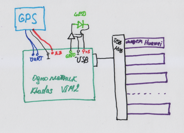
I decided to implement the entire project in Python, despite having no experience in development in this language at all. I chose it because there were plenty of ready-made examples and solutions that could speed up development. Therefore, I ask all professional programmers not to criticize my first experience in Python, and I am always eager to hear constructive feedback to improve my skills.
I also discovered that Python has two main versions 2 and 3, so I settled on the third.
Hardware Components
Single-board computer vim2
As the main machine, I was given a single-board computer
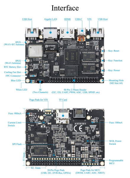
An excellent, powerful media hub for smart homes and SMART TVs, but rather unsuitable for this task, or let's say, poorly suited. For example, its main OS is Android, whereas Linux is a secondary OS, and accordingly, no one guarantees the proper functioning of all nodes and drivers under Linux. I suspect that some issues were related to the USB drivers of this platform, which is why modems did not perform as expected. Additionally, it has very poor and fragmented documentation, making each operation take a lot of time digging through the docs. Even basic work with GPIO drained a lot of my energy. For instance, it took me several hours to configure the LED. However, to be objective, it wasn't critically important what kind of single-board computer it was, the main thing was that it worked and had USB ports.
First, I need to install Linux on this board. To avoid rummaging through the depths of the documentation, and for those who will be figuring out this single-board computer, I am writing this chapter.
There are two options to install Linux: on an external SD card, or on internal MMC. I struggled with the card for a while and couldn't figure out how to make it work, so I decided to install it on MMC, although undoubtedly it would have been much easier to work with an external card.
About the firmware . I am translating from the strange to Russian. To flash the board, I need to connect the hardware UART. I connected it
- Tool Pin GND: Pin17 of VIM’s GPIO
- Tool Pin TXD: Pin18 of VIM’s GPIO (Linux_Rx)
- Tool Pin RXD: Pin19 of VIM’s GPIO (Linux_Tx)
- Tool Pin VCC: Pin20 of VIM’s GPIO
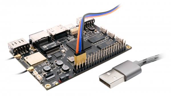
After that, I downloaded the firmware . The specific firmware version is .
To flash this firmware, I need some utilities. More details about this are explained . I haven’t tried flashing under Windows, but I should mention a few words about the flashing process under Linux. First, I will install the utilities according to the instructions.
git clone https://github.com/khadas/utils
cd /path/to/utils
sudo ./INSTALL
And… Nothing works. I spent a couple of hours tweaking installation scripts to get everything installed correctly. I don't remember what I did, but it was quite a circus. So be cautious. But without these utilities, there’s no point in further struggling with vim2. It's better to avoid it altogether!
After seven circles of hell, configuring scripts and installations, I have a set of working utilities. I connected the board via USB to my Linux computer, and the UART is also connected according to the diagram above.
I’m setting up my favorite terminal, minicom, at a speed of 115200, with no hardware or software error control. Let’s get started.
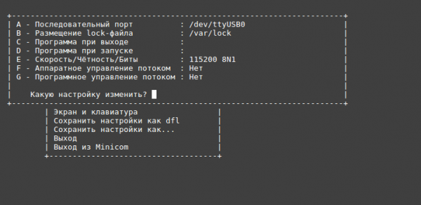
When loading VIM2 in the UART terminal, I press any key, for example, the space bar, to stop the boot process. After the line appears,
kvim2# I enter the command:
kvim2# run updateOn the host from which we are booting, I execute:
burn-tool -v aml -b VIM2 -i VIM2_Ubuntu-server-bionic_Linux-4.9_arm64_EMMC_V20191231.imgThat's it, phew. Flashed, and the board now has Linux. Login/password khadas:khadas.
After that, a few initial settings. For further work, I disable the sudo password (yes, it's not secure, but convenient).
sudo visudoI edit the line to look like this and save it
# Allow members of group sudo to execute any command
%sudo ALL=(ALL:ALL) NOPASSWD: ALL
After that, I change the current locale to set the time to Moscow time; otherwise, it will be Greenwich Mean Time.
sudo timedatectl set-timezone Europe/Moscowor
ln -s /usr/share/zoneinfo/Europe/Moscow /etc/localtimeIf this seems complicated to you, then don’t use this board; it's better to go for a Raspberry Pi. Honestly.
Huawei e3372h modem — 153
This modem has caused me quite a bit of trouble, and essentially, it became the bottleneck of the entire project. In general, calling these devices "modems" doesn't reflect their functionality well: they are powerful multipurpose devices that simulate a CD-ROM to install drivers and then switch to network card mode.
Architecturally, from a Linux user's perspective after all the settings, it looks like this: after connecting the modem, I have a network interface eth* that receives the IP address 192.168.8.100 via DHCP, and the default gateway is 192.168.8.1.
And the most important point! This model of the modem cannot operate in the mode of a modem that is controlled by AT commands.It would be much simpler to create PPP connections for each modem and then operate with them. But in my case, ‘itself’ (more precisely, the Linux driver according to udev rules) creates the eth interface and assigns it an IP address via DHCP.
To avoid confusion, I suggest we forget the term ‘modem’ and refer to it as a network card and gateway, because essentially, it is like connecting a new network card with a gateway.
When there is one modem, this does not pose any major problems, but when there are several, specifically n modems, the following network picture arises.
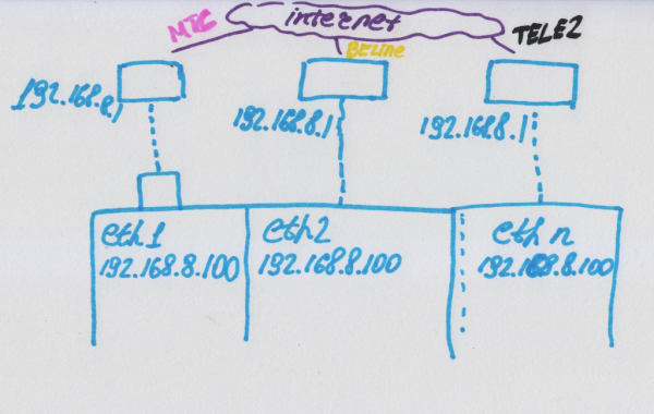
That is, n network cards, each with one IP address, all sharing the same default gateway. However, in fact, each is connected to its own operator.
Initially, I had a simple solution: using the ifconfig or ip commands to shut down all interfaces and turn them on one by one to test them. The solution was fine except that during switching, I was unable to connect to the device. Since the switching was frequent and fast, I effectively had no way to connect at all.
Therefore, I chose to manually change the IP addresses of the modems and route traffic using routing settings.
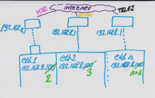
My problems with the modems did not end there: in case of power issues, they would drop out, requiring a stable power supply for the USB hub. I solved this issue by soldering the power directly to the hub. Another problem I faced, which doomed the entire project, was that after rebooting or cold starting, not all modems were recognized, and I couldn't figure out why this was happening or what the algorithm was. But let's take it step by step.
For the modem to work correctly, I installed the usb-modeswitch package.
sudo apt update
sudo apt install -y usb-modeswitch
After this, the modem will be correctly identified and configured by the udev subsystem upon connection. I check by simply plugging in the modem and confirming that the network appeared.
Another issue I couldn't resolve: how to get the name of the operator from this modem? The operator's name is located in the modem's web interface at 192.168.8.1. This is a dynamic web page that retrieves data via ajax requests, so simply using wget to fetch the page and parse the name won't work. Therefore, I started looking at how to interact with the web page, etc., and realized I was dealing with something pointless. As a result, I gave up and started retrieving the operator's name using the API of Speedtest.
Much would be simpler if the modem had access through AT commands. I could reconfigure it, create a PPP connection, assign an IP, get the service provider, etc. But alas, I am stuck with what I have.
GPS
The GPS receiver that was issued to me had a UART interface and power supply. It wasn't the best solution, but it was nonetheless functional and straightforward. The receiver looked something like this.
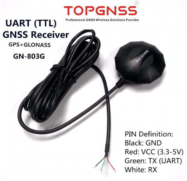
Honestly, it was my first time working with a GPS receiver, but as expected, everything was already figured out for us. So we just use ready-made solutions.
To start, I enable uart_AO_B (UART_RX_AO_B, UART_TX_AO_B) to connect the GPS.
khadas@Khadas:~$ sudo fdtput -t s /dtb.img /serial@c81004e0 status okayAfter that, I check the success of the operation.
khadas@Khadas:~$ fdtget /dtb.img /serial@c81004e0 status
okay
This command, it seems, edits the devtree on-the-fly, which is quite convenient.
After the success of this operation, we reboot and install the GPS daemon.
khadas@Khadas:~$ sudo rebootInstalling the GPS daemon. I install everything and disable it immediately for further configuration.
sudo apt install gpsd gpsd-clients -y
sudo killall gpsd

/* GPS daemon stop/disable */
sudo systemctl stop gpsd.socket
sudo systemctl disable gpsd.socket
I edit the configuration file.
sudo vim /etc/default/gpsdI set up the UART on which the GPS will be connected.
DEVICES="/dev/ttyS4"And then we enable everything and start it.
/* GPS daemon enable/start */
sudo systemctl enable gpsd.socket
sudo systemctl start gpsd.socket
After that, I connect the GPS.
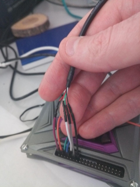
In my hands, I have the GPS wire, and beneath my fingers are the UART debugger wires.
I reboot and check the GPS operation using the gpsmon program.
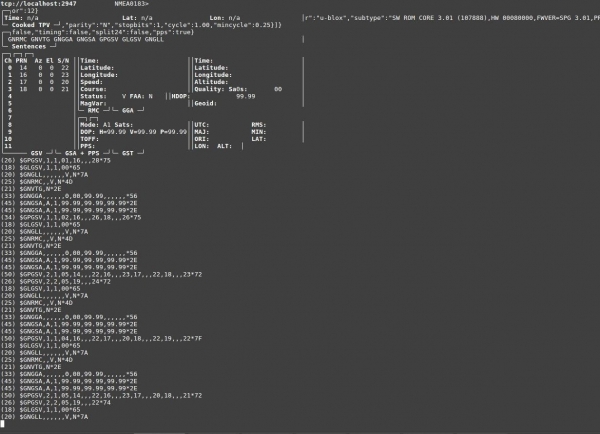
In this screenshot, no satellites are visible, but there is communication with the GPS receiver, indicating that everything is fine.
I tried many options for working with this daemon in Python, but I settled on the one that worked correctly with Python 3.
I install the necessary library.
sudo -H pip3 install gps3 And I shape the working code.
from gps3.agps3threaded import AGPS3mechanism
...
def getPositionData(agps_thread):
	counter = 0;
	while True:
		longitude = agps_thread.data_stream.lon
		latitude = agps_thread.data_stream.lat
		if latitude != 'n/a' and longitude != 'n/a':
			return '{}' .format(longitude), '{}' .format(latitude)
		counter = counter + 1
		print ("Wait gps counter = %d" % counter)
		if counter == 10:
			ErrorMessage("GPS receiver error!!!")
			return "NA", "NA"
		time.sleep(1.0)
...
f __name__ == '__main__':
...	#gps
	agps_thread = AGPS3mechanism()  # Instantiate AGPS3 Mechanisms
	agps_thread.stream_data()  # From localhost (), or other hosts, by example, (host='gps.ddns.net')
	agps_thread.run_thread()  # Throttle time to sleep after an empty lookup, default '()' 0.2 two tenths of a second
If I need to get the coordinates, this is done with the following call:
longitude, latitude = getPositionData(agps_thread)
Within 1-10 seconds, I will either receive the coordinates, or I won't. Yes, I had ten attempts to get the coordinates. It’s not optimal, clumsy, and awkward, but it works. I decided to do this because GPS can catch poorly and not always provide data. If I wait for the data to be retrieved, in the case of working in a dead zone, the program will hang at that point. Therefore, I implemented this inelegant solution.
In principle, if there were more time, I could retrieve data from the GPS directly via UART, parse it in a separate thread, and work with it. But there was absolutely no time, hence the terribly ugly code. And yes, I’m not ashamed.
LED
Connecting the LED was both simple and complicated at the same time. The main difficulty is that the pin number in the system does not correspond to the pin number on the board, and because the documentation is poorly written. To match the hardware pin number and the pin number in the OS, you need to execute the command:
gpio readallA table mapping the pin in the system to the pin on the board will be displayed. After that, I can manipulate the pin in the OS. In my case, the LED is connected to GPIOH_5.
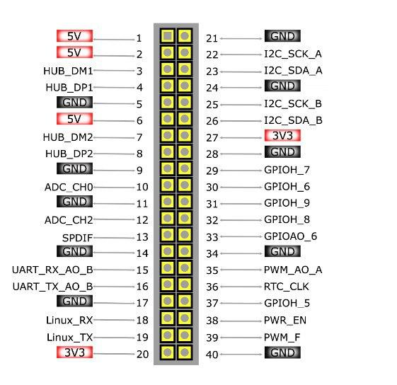
I set the GPIO pin to output mode.
gpio -g mode 421 outI write zero.
gpio -g write 421 0I write one.
gpio -g write 421 1 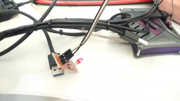
It’s all lit up after writing ‘1’
#gpio subsistem
def gpio_init():
	os.system("gpio -g mode 421 out")
	os.system("gpio -g write 421 1")

def gpio_set(val):
	os.system("gpio -g write 421 %d" % val)

def error_blink():
	gpio_set(0)
	time.sleep(0.1)
	gpio_set(1)
	time.sleep(0.1)
	gpio_set(0)
	time.sleep(0.1)
	gpio_set(1)
	time.sleep(0.1)
	gpio_set(0)
	time.sleep(1.0)
	gpio_set(1)

def good_blink():
	gpio_set(1)
Now, in case of errors, I call error_blink() and the LED blinks beautifully for us.
Software modules
Speedtest API
The great joy is that the service speedtest.net has its own python API, which can be viewed at .
What’s nice is that there are source codes, which can also be checked out. How to work with this API (simple examples) can be seen in .
I install the python library with the following command.
sudo -H pip3 install speedtest-cliAs an example, you can even install the speed tester in Ubuntu directly from the repository. It’s the same python application that can then be launched straight from the console.
sudo apt install speedtest-cli -yAnd conduct measurements of your internet speed.
speedtest-cli
 Retrieving speedtest.net configuration...
 Testing from B***** (*.*.*.*)...
 Retrieving speedtest.net server list...
 Selecting best server based on ping...
 Hosted by MTS (Moscow) [0.12 km]: 11.8 ms
 Testing download speed................................................................................
 Download: 7.10 Mbit/s
 Testing upload speed......................................................................................................
 Upload: 3.86 Mbit/s
As a result, as I did it. I had to dive into the source codes of this speed test to integrate them more fully into my project. One of the most important tasks is to also get the name of the telecom operator to insert it into the table.
import speedtest
from datetime import datetime
...
#Specify a specific server for the test
#6053) MaximaTelecom (Moscow, Russian Federation)
servers = ["6053"]
# If you want to use a single threaded test
threads = None
s = speedtest.Speedtest()
#get the name of the mobile network operator
opos = '%(isp)s' % s.config['client']
s.get_servers(servers)
#obtain a text string with the server parameters
testserver = '%(sponsor)s (%(name)s) [%(d)0.2f km]: %(latency)s ms' % s.results.server
#download test
s.download(threads=threads)
#upload test
s.upload(threads=threads)
#get results
s.results.share()

#After which a string is formed for writing to a csv file.
#get GPS position
longitude, latitude = getPositionData(agps_thread)
#current time and date
curdata = datetime.now().strftime('%d.%m.%Y')
curtime = datetime.now().strftime('%H:%M:%S')
delimiter = ';'
result_string = opos + delimiter + str(curpos) + delimiter +
	curdata + delimiter + curtime + delimiter + longitude + ', ' + latitude + delimiter +
	str(s.results.download/1000.0/1000.0) + delimiter + str(s.results.upload / 1000.0 / 1000.0) +
	delimiter + str(s.results.ping) + delimiter + testserver + "n"
#this is where the log file is written
It also turned out to be not so simple here, although it might seem straightforward. Initially, the servers parameter was set to [], meaning to pick the best server. As a result, I had random servers, and as you can easily guess, fluctuating speeds. It's quite a complex topic; using a fixed server—whether static or dynamic—requires research. But here's an example of speed measurement graphs from the Beeline operator with dynamically chosen test servers versus a statically fixed one.
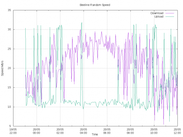
Speed measurement results when choosing a dynamic server.
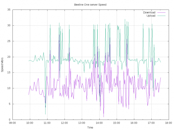
Speed testing results with a strictly selected single server.
There is "noise" during testing here and there, which needs to be eliminated using mathematical methods. But with a fixed server, it is somewhat less and the amplitude is more stable.
In general, this is a place for extensive research. I would conduct speed measurements to my server using the iperf utility. But we adhere to the terms of reference.
Email Sending and Errors
For sending emails, I tried several dozen different options but ultimately settled on the following. I registered an email account at Yandex and then took . I tested it and integrated it into the program. In this example, various options are discussed, including sending from Gmail, etc. I didn't want to deal with setting up my own mail server, and I didn't have time for it, but as it turned out later, it was also unnecessary.
Logs were sent using the scheduler, when there is a connection, every 6 hours: at midnight, 6 AM, noon, and 6 PM. They were sent as follows.
from send_email import *
...
message_log = "Testing logs for board #1"
EmailForSend = ["dlinyj@trololo.ru", "pupkin@trololo.ru"]
files = ["/home/khadas/modems_speedtest/csv"]
...
def sendLogs():
	global EmailForSend
	curdata = datetime.now().strftime('%d.%m.%Y')
	curtime = datetime.now().strftime('%H:%M:%S')
	try:
		for addr_to in EmailForSend:
			send_email(addr_to, message_log, "Logs for " + curdata + " " + curtime, files)
	except:
		print("Network problem for sending mail")
		return False
	return True
Errors were also initially sent. Initially, they were accumulated in a list and then sent through the scheduler when there was a connection. However, later problems arose because Yandex has a limitation on the number of messages sent per day (it's a pain, sadness, and humiliation). Since there could have been a significant number of errors even per minute, we had to abandon sending errors via email. So be aware of this problem when using Yandex services for automated sending.
Feedback server
In order to access the remote hardware and have the ability to reconfigure it, I needed an external server. To be fair, it would be more appropriate to send all the data to the server and build all the beautiful graphs in the web interface. But not everything at once.
As a VPS, I chose . I could have taken the simplest server, which would have been more than enough for my purposes. However, since I wasn't paying for the server out of my own pocket, I decided to go for something with a bit of a buffer in case we expand to a web interface, set up our own SMTP server, VPN, etc. Plus, to have the ability to configure a Telegram bot and avoid any issues with its blocks. Therefore, I chose Amsterdam and the following parameters.
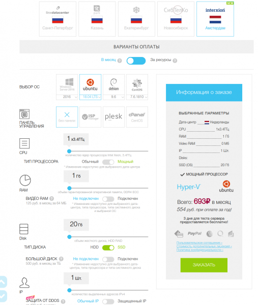
For the connection with the hardware vim2, I chose a reverse SSH connection, which, as practice showed, is not the best option. When the connection is broken, the server holds the port, and it's impossible to connect for a while. Therefore, it is still better to use other communication methods, such as VPN. In the future, I wanted to switch to a VPN, but I didn't have the time.
I won't go into the details of configuring the firewall, managing user permissions, disabling root SSH access, and other basic VPS setup truths. I hope you are already familiar with them. For remote access, I create a new user on the server.
adduser vimsshOn our machine, I generate SSH connection keys.
ssh-keygenAnd I copy them to our server.
ssh-copy-id vimssh@host.comOn our machine, I set up automatic reverse SSH connection on every boot.
[Unit]
 Description=Auto Reverse SSH
 Requires=systemd-networkd-wait-online.service
 After=systemd-networkd-wait-online.service
 [Service]
 User=khadas
 ExecStart=/usr/bin/ssh -NT -o ExitOnForwardFailure=yes -o ServerAliveInterval=60 -CD 8080 -R 8083:localhost:22 vimssh@host.com
 RestartSec=5
 Restart=always
 [Install]
 WantedBy=multi-user.target
Note the port 8083: it defines the port through which I will connect via reverse SSH. We add it to the autostart and start it.
sudo systemctl enable autossh.service
sudo systemctl start autossh.service
You can even check the status:
sudo systemctl status autossh.serviceNow, on our VPS server, if I run:
ssh -p 8083 khadas@localhostI access my test machine. From the machine, I can also send logs and any data over SSH to my server, which is very convenient.
Bringing it all together
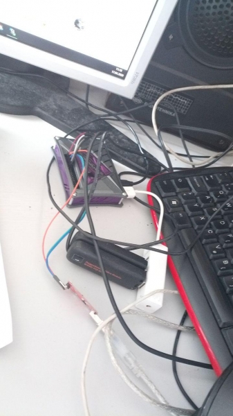
Turning on, we proceed to development and debugging.
Phew, I’ve described all the components. Now it's time to put it all together. You can view the code. .
An important point with the code: This project may not run 'straight out of the box' since it was tailored for a specific task and architecture. Although I'm providing the source code, I’ll explain the most valuable parts right here in the text, otherwise it’ll be completely unclear.
At the beginning, I initialize GPS, GPIO, and start a separate scheduler thread.
#запуск потока планировщика
pShedulerThread = threading.Thread(target=ShedulerThread, args=(1,))
pShedulerThread.start()
The scheduler is quite simple: it checks if it's time to send messages and what the current error status is. If there’s an error flag, we blink an LED.
#sheduler
def ShedulerThread(name):
	global ready_to_send
	while True:
		d = datetime.today()
		time_x = d.strftime('%H:%M')
		if time_x in time_send_csv:
			ready_to_send = True
		if error_status:
			error_blink()
		else:
			good_blink()
		time.sleep(1)
The most challenging part of this project is maintaining the reverse SSH connection during each test. In each test, the default gateway and DNS server settings are reapplied. Since no one reads this anyway, just know that the train doesn't run on wooden rails. Whoever finds the Easter egg gets a candy.
To accomplish this, I create a separate routing table —set-mark 0x2 and a rule for redirecting traffic.
def InitRouteForSSH():
	cmd_run("sudo iptables -t mangle -A OUTPUT -p tcp -m tcp --dport 22 -j MARK --set-mark 0x2")
	cmd_run("sudo ip rule add fwmark 0x2/0x2 lookup 102")
You can read more about how this works .
After that, I enter an infinite loop where I retrieve the list of connected modems each time (to check if the network configuration has changed).
network_list = getNetworklist()Obtaining the list of network interfaces is quite simple.
def getNetworklist():
	full_networklist = os.listdir('/sys/class/net/')
	network_list = [x for x in full_networklist if 'eth' in x and x != 'eth0']
	return network_list
After obtaining the list, I assign IP addresses to all interfaces, as shown in the image in the chapter about modems.
SetIpAllNetwork(network_list)

def SetIpAllNetwork(network_list):
	for iface in network_list:
		lastip = '%d' % (3 + network_list.index(iface))
		cmd_run('sudo ifconfig ' + iface + ' 192.168.8.' + lastip + ' up')
Next, I simply iterate through each interface and configure each one.
	for iface in network_list:
		ConfigNetwork(iface)
def ConfigNetwork(iface):
# Reset all settings
cmd_run('sudo ip route flush all')
# Assign default gateway
cmd_run('sudo route add default gw 192.168.8.1 ' + iface)
# Set DNS server (needed for speedtest)
cmd_run('sudo bash -c "echo nameserver 8.8.8.8 > /etc/resolv.conf"')I check the interface for functionality; if there is no network, I generate errors. If there is a network, it's time to act!
Here, I configure SSH routing on this interface (if it hasn't been done), send errors to the server, and when the time comes, I send logs, and finally perform a speedtest, saving the logs to a CSV file.
if not NetworkAvalible():
....
# Here we generate errors
....
else: # The network is available, hooray, let's work!
# If we have a problematic interface where SSH is, we change it
  if (sshint == lastbanint or sshint == 'free'):
    print('********** Setup SSH ********************')
    if sshint != 'free':
      cmd_run('sudo ip route del default via 192.168.8.1 dev ' + sshint + ' table 102')
    SetupReverseSSH(iface)
    sshint = iface
# Since the network is working, let's urgently send everything!!!
    if ready_to_send:
      print('**** Ready to send!!!')
        if sendLogs():
          ready_to_send = False
        if error_status:
          SendErrors()
# and then test the speed and save the logs.
It is worth mentioning the function for configuring reverse SSH.
def SetupReverseSSH(iface):
	cmd_run('sudo systemctl stop autossh.service')
	cmd_run('sudo ip route add default via 192.168.8.1 dev ' + iface + ' table 102')
	cmd_run('sudo systemctl start autossh.service')
And of course, it is necessary to add all this beauty to startup. For this, I create a file:
sudo vim /etc/systemd/system/modems_speedtest.serviceAnd I write in it:
[Unit]
 Description=Modem Speed Test
 Requires=systemd-networkd-wait-online.service
 After=systemd-networkd-wait-online.service
 [Service]
 User=khadas
 ExecStart=/usr/bin/python3.6 /home/khadas/modems_speedtest/networks.py
 RestartSec=5
 Restart=always
 [Install]
 WantedBy=multi-user.target
I enable autostart and start it!
sudo systemctl enable modems_speedtest.service
sudo systemctl start modems_speedtest.service
Now I can view the logs of what is happening using the command:
journalctl -u modems_speedtest.service --no-pager -fResults
Well, now the most important question is, what was the result? I will present several graphs that I managed to capture during the development and debugging process. The graphs were created using gnuplot with the following script.
#! /usr/bin/gnuplot -persist
set terminal postscript eps enhanced color solid
set output "Rostelecom.ps"

#set terminal png size 1024, 768
#set output "Rostelecom.png"

set datafile separator ';'
set grid xtics ytics
set xdata time
set ylabel "Speed Mb/s"
set xlabel 'Time'
set timefmt '%d.%m.%Y;%H:%M:%S'
set title "Rostelecom Speed"

plot "Rostelecom.csv" using 3:6 with lines title "Download", '' using 3:7 with lines title "Upload"

set title "Rostelecom 2 Ping"
set ylabel "Ping ms"
plot "Rostelecom.csv" using 3:8 with lines title "Ping"
The first experiment was conducted with the Tele2 operator over several days.
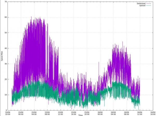
Here I used a dynamic measuring server. The speed measurements work, but they fluctuate quite a bit; however, some average value is still visible, and it can be obtained by filtering the data, for example, using a moving average.
Later, I built several more graphs for other telecom operators. In this case, there was already a single testing server, and the results were also very interesting.
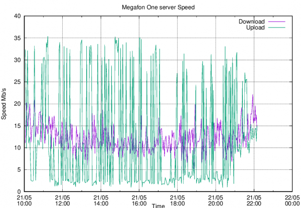
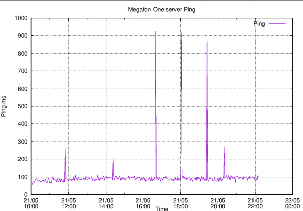
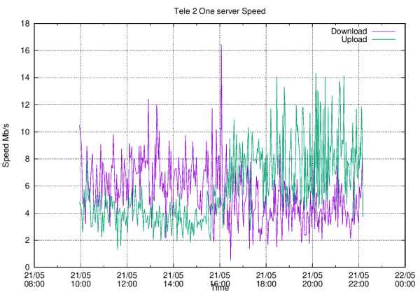
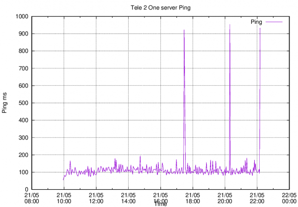
As can be seen, the topic is quite extensive for research and data processing and clearly requires more than a couple of weeks of work. But...
Conclusion of the work
The work was abruptly halted due to circumstances beyond my control. One of the weak points of this project, in my subjective view, was the modem, which did not cooperate well with other modems and caused such issues at every reboot. For these purposes, there are numerous other modem models available, usually in Mini PCI-e format, which are installed inside the device and are much easier to configure. But that is a completely different story. The project was interesting, and I was very glad to have participated in it.
Source: habr.com
