


This article opens a series dedicated to automated methods of tuning PID controllers in the Simulink environment. Today, we will explore how to work with the PID Tuner application.
Introduction
The most popular type of controllers used in industry within closed-loop control systems is the PID controller. While engineers remember the structure and operating principle of the controller from their student days, tuning it, that is, calculating the controller coefficients, remains a challenge. There is a vast amount of literature, both foreign (for example, [1, 2]) and domestic (for example, [3, 4]), that explains controller tuning using quite complex automated control theory language.
This series of articles will describe automated methods of tuning PID controllers using tools in the Simulink environment, such as:
- PID Tuner,
- Response Optimizer,
- Control System Tuner,
- Frequency Response Based PID Tuner,
- Closed-Loop PID Autotuner.
The control system will be based on a DC motor with permanent magnet excitation, operating in conjunction with a gearbox under inertial load with the following parameters:
- motor supply voltage,
 ;
; - active resistance of the motor armature winding, ;
- inductive resistance of the motor armature winding, ;
- motor torque constant, ;
- rotor moment of inertia of the motor, .
 ;
;  ;
;  ;
;  ;
;  .
.Load and gearbox parameters:
- load moment of inertia, ;
- gearbox transmission ratio, .
 ;
;  .
.The articles contain virtually no mathematical formulas; however, it is desirable for the reader to have basic knowledge of control theory and experience with modeling in Simulink to understand the material presented.
System Model
We will consider a linear control system for the angular velocity of a tracking electric drive, whose simplified structural diagram is presented below.

In accordance with the provided structure, a model of such a system was built in the Simulink environment.

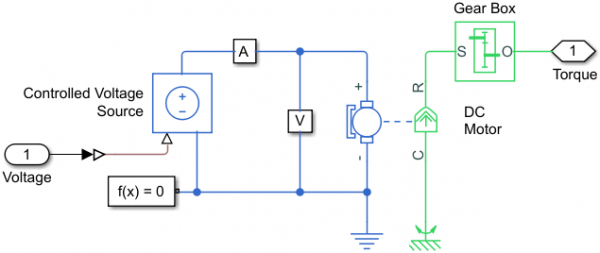
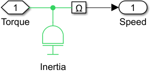
Models of the electric drive (Electric actuator subsystem) and inertial load (Load subsystem) were created using blocks from the physical modeling library :
- electric drive model,
- inertia load model.
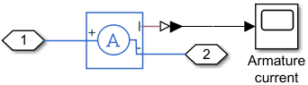
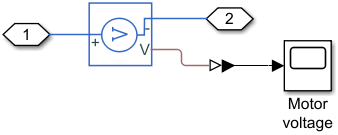
The models of the electric drive and loads also include subsystems of sensors for various physical quantities:
- current flowing in the motor armature winding (Subsystem A),
- voltage across its winding (Subsystem V),
- angular velocity of the controlled object (Subsystem Ω).
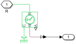
Before setting the PID controller parameters, we will run the model for simulation, taking the transfer function of the controller  . The simulation results for the input signal of 150 rpm are shown below.
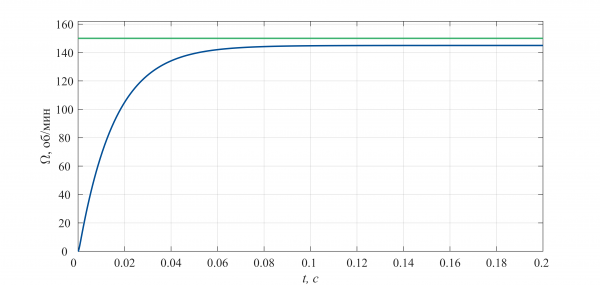
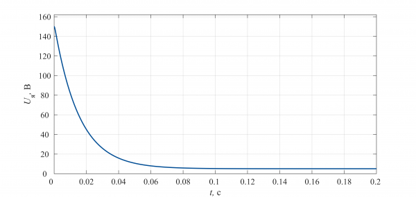
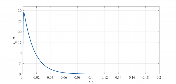
From the analysis of the presented graphs, it can be seen that:
- The output coordinate of the control system does not reach the specified value, i.e., there is a static error in the system.
- The voltage across the motor windings reaches a value of 150 V at the beginning of the simulation, which will lead to its failure due to the application of voltage exceeding the nominal (24 V) to its winding.
Let the system's response to a unit impulse meet the following requirements:
- overshoot no more than 10%,
- rise time less than 0.8 s,
- settling time less than 2 s.
In addition, the controller must limit the voltage applied to the motor winding to the supply voltage value.
Configuring the controller
Controller parameter settings are done using the , which is available directly in the PID Controller block parameter window.
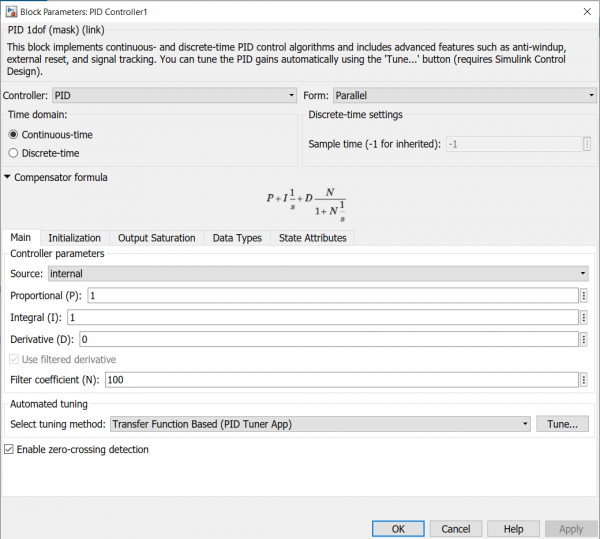
The application is launched by pressing the button Tune…, located on the Automated tuning. It is worth noting that before performing the controller parameter tuning stage, it is necessary to select its type (P, PI, PD, etc.) and also its kind (analog or discrete).
Since one of the requirements is to limit its output coordinate (voltage on the motor winding), the allowed voltage range should be set. To do this:
- We go to the Output Saturation.
- We press the flag button Limit output, which activates fields for setting the upper (Upper limit) and lower (Lower limit) boundaries of the output range.
- We set the range boundaries.
The correct operation of the regulator block within the system requires methods aimed at combating integral saturation. Two methods are implemented in the block: back-calculation and clamping. Detailed information about these methods can be found . The dropdown menu for method selection is located on the panel Anti-windup.
In the current case, we will enter the values 24 and -24 into the fields Upper limit and Lower limit respectively, and we will also use the clamping method to exclude integral saturation.
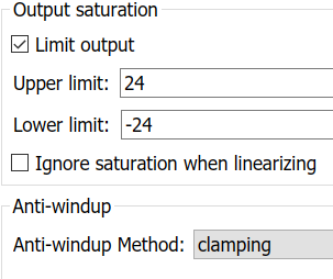
It can be seen that the appearance of the regulator block has changed: a saturation sign has appeared next to the output port of the block.
Next, after applying all changes by clicking the button Apply, we return to the tab Main and click the button Tune…, which will open a new window of the PIDTuner application.
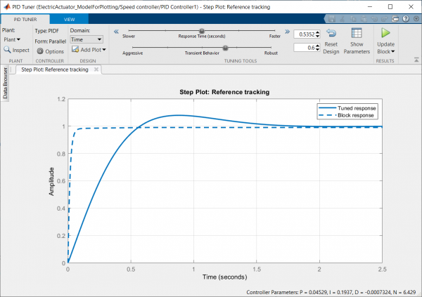
In the graphical area of the window, two transient processes are displayed: for the current regulator parameters, i.e., for the untuned regulator, and for the values automatically adjusted. New parameter values can be viewed by clicking the button Show Parameters, located on the toolbar. Upon clicking the button, two tables will appear: the tuned regulator parameters (Controller Parameters) and the generated assessments of the transient process characteristics with the tuned parameters (Performance and Robustness).
As can be seen from the values in the second table, the automatically calculated regulator coefficients meet all requirements.
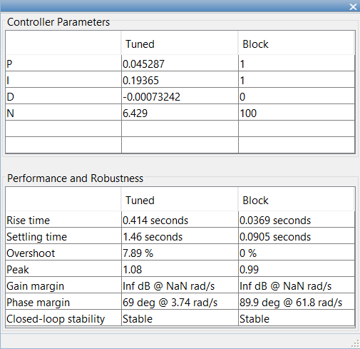
The tuning of the regulator is completed by pressing the button with the green triangle located to the right of the button Show Parameters, after which the new parameter values will automatically change in the corresponding fields in the PID Controller parameter settings window.
The simulation results of the system with the tuned regulator for several input signals are shown below. At higher input signal levels (blue line), the system will operate in voltage saturation mode.
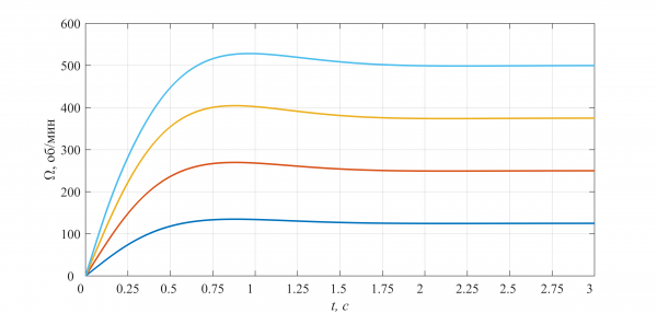
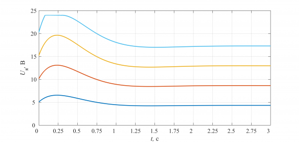
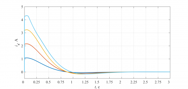
It should be noted that the PID Tuner tool selects the regulator coefficients based on the linearized model, so when transitioning to a nonlinear model, its parameters need to be refined. In this case, you can use the application .
Literature
- Handbook of PI and PID Controller Tuning Rules. Aidan O’Dwyer
- PID Control System Design and Automatic Tuning using MATLAB, Simulink. Wang L.
- PID control in a non-strict exposition. Karpov V.E.
- PID Controllers. Implementation Issues. Parts 1, 2. Denisenko V.
Source: habr.com
