

1. Introduction
The task at hand was to develop a communication protocol between the nrf52832 microcontroller and two half-bridge Chinese load cells.
The task turned out to be challenging due to the lack of clear information. Likely, the "root of the problem" lies within the SDK from Nordic Semiconductor — constant version updates, some redundancy, and functional complexity. I had to write everything from scratch.
I believe this topic is quite relevant given that this chip features a BLE stack and a whole set of energy-saving "goodies." However, I won't delve too deeply into the technical aspects, as there are already many articles written on this subject.
2. Project Description
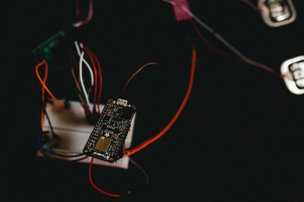
Hardware:
- Adafruit Feather nRF52 Bluefruit LE (what was at hand)
- HX711 ADC
- Two Chinese load cells (50x2 kg)
- ST-LINK V2 programmer
Software:
- VSCODE IDE
- NRF SDK 16
- OpenOCD
- ST-LINK V2 programmer
Everything is contained in one project, it will just require some adjustments to the Makefile (specify the location of your SDK).
3. Code Description
We will use the GPIOTE module for peripheral interaction based on task and event binding, as well as the PPI module to transfer data from one peripheral to another without CPU involvement.
ret_code_t err_code;
   err_code = nrf_drv_gpiote_out_init(PD_SCK, &config); // configuring as output
   nrf_drv_gpiote_out_config_t config = GPIOTE_CONFIG_OUT_TASK_TOGGLE(false); // toggling the pin for pulses
   err_code = nrf_drv_gpiote_out_init(PD_SCK, &config); // configuring as output
We configure the PD_SCL synchronization line as an output to generate pulses with a duration of 10 μs.
   nrf_drv_gpiote_in_config_t gpiote_config = GPIOTE_CONFIG_IN_SENSE_HITOLO(false); // level transition from high to low
   nrf_gpio_cfg_input(DOUT, NRF_GPIO_PIN_NOPULL); // input without pull-up
   err_code = nrf_drv_gpiote_in_init(DOUT, &gpiote_config, gpiote_evt_handler);
static void gpiote_evt_handler(nrf_drv_gpiote_pin_t pin, nrf_gpiote_polarity_t action)
{
nrf_drv_gpiote_in_event_disable(DOUT); // disable the interrupt
nrf_drv_timer_enable(&m_timer0); // enable the timer
}
We configure the DOUT data line to read the readiness state of the HX711; when a low level is detected, the handler is triggered, where we disable the interrupt and start the timer to generate synchronization pulses on the PD_SCL output.
 err_code = nrf_drv_ppi_channel_alloc(&m_ppi_channel1);
   APP_ERROR_CHECK(err_code);
   err_code = nrf_drv_ppi_channel_assign(m_ppi_channel1,                                         nrf_drv_timer_event_address_get(&m_timer0, NRF_TIMER_EVENT_COMPARE0),                                           nrf_drv_gpiote_out_task_addr_get(PD_SCK)); // connect timer to output
   APP_ERROR_CHECK(err_code);
   err_code = nrf_drv_ppi_channel_enable(m_ppi_channel1); // enable channel
   APP_ERROR_CHECK(err_code);
   nrf_drv_gpiote_out_task_enable(PD_SCK);
// включаем gpiote
Next, we initialize the PPI module and connect our timer to the PD_SCL output to generate pulses lasting 10 microseconds when a comparison event occurs, and we also enable the GPIOTE module.
nrf_drv_timer_config_t timer_cfg = NRF_DRV_TIMER_DEFAULT_CONFIG; // by default
   timer_cfg.frequency = NRF_TIMER_FREQ_1MHz; // clocking at 1MHz
   ret_code_t err_code = nrf_drv_timer_init(&m_timer0, &timer_cfg, timer0_event_handler);
   APP_ERROR_CHECK(err_code);
   nrf_drv_timer_extended_compare(&m_timer0,
                                  NRF_TIMER_CC_CHANNEL0,
                                  nrf_drv_timer_us_to_ticks(&m_timer0,
                                                            10),
                                  NRF_TIMER_SHORT_COMPARE0_CLEAR_MASK,
                                  true); // triggers on comparison
We initialize the zero timer and its handler.
  if(m_counter%2 != 0 && m_counter<=48){
       buffer <<= 1; // variable for read data
        c_counter++; // count of positive impulses
           if(nrf_gpio_pin_read(DOUT)) buffer++; // read input state
   }
The most interesting part happens in the timer handler. The pulse period is 20 microseconds. We are interested in the odd pulses (on the rising edge) under the condition that their count does not exceed 24, while the total events are 48. With each odd event, we read DOUT.
According to the datasheet, the number of pulses should be at least 25, which corresponds to a gain coefficient of 128 (in the code, I used 25 pulses); this is equivalent to 50 timer events, indicating the end of the data frame.
 ++m_counter; // event counter
if(m_counter==50){
      nrf_drv_timer_disable(&m_timer0); // disable timer
       m_simple_timer_state = SIMPLE_TIMER_STATE_STOPPED; //
       buffer = buffer ^ 0x800000;
       hx711_stop(); // disable hx711
       }
After that, we disable the timer and process the data (according to the datasheet) and switch the HX711 to low power mode.
static void repeated_timer_handler(void * p_context)
{
   nrf_drv_gpiote_out_toggle(LED_2);
   if(m_simple_timer_state == SIMPLE_TIMER_STATE_STOPPED){
      	hx711_start(); // starting hx711
       nrf_drv_gpiote_out_toggle(LED_1);
       m_simple_timer_state = SIMPLE_TIMER_STATE_STARTED;
   }

}
/**@brief Create timers.
*//
static void create_timers()
{
   ret_code_t err_code;

   // Create timers
   err_code = app_timer_create(&m_repeated_timer_id,
                               APP_TIMER_MODE_REPEATED,
                               repeated_timer_handler);
   APP_ERROR_CHECK(err_code);
}
Waiting for an event from the RTC timer with an interval of 10 seconds (this is at your discretion), in the handler we start HX711, calling an interrupt on the DOUT line.
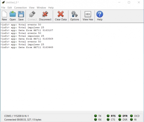
There's one more aspect to consider: logs are output via UART (baud rate 115200, TX — pin 6, RX — pin 8) all settings are located in sdk_config.h.
Conclusions
Thank you all for your attention; I hope this article will be useful and save precious time for developers searching for a solution. I want to say that the technical approach used by Nordic in their platforms is quite interesting in terms of energy efficiency.
P.S.
The project is still in development, so if there is interest in this topic, in the next article, I will try to describe the algorithm for calibrating weight sensors, as well as connecting the BLE stack.
Materials
Source: habr.com
