

DIY, as Wikipedia states, has long been a subculture. In this article, I want to share my DIY project of a small wireless multi-sensor device, which will be my modest contribution to this subculture.
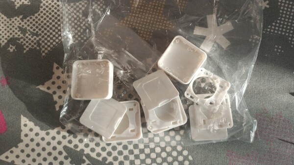
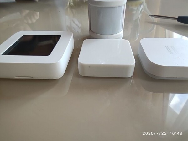
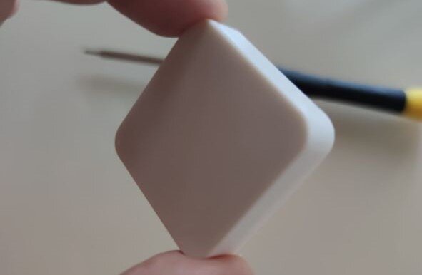
The history of this project began with the casing, which sounds silly, but that's how this project started. The case was purchased from AliExpress, and I must note that the quality of the plastic mold is excellent. After a brief correspondence with the seller, a blueprint was sent via email, and this project began.
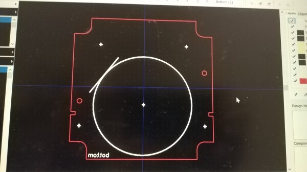
The blueprint itself was poorly dimensioned, and half of the measurements for the boundaries, cutouts, and technological openings of the future printed circuit board had to be made using calipers. Once I got all the internal dimensions of the case, it became clear that the radio chip would have to be 'laid out' directly on the PCB, as the height from the top of the PCB to the inner surface of the case was 1.8 mm, while the minimum height of an average radio module is usually 2 mm (without a screen).
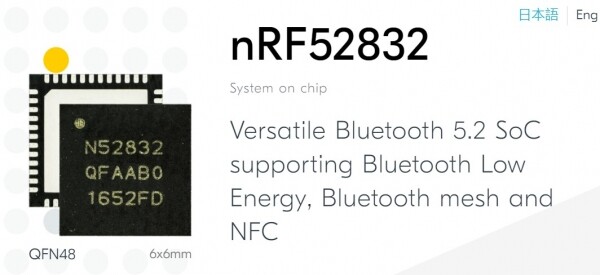
For the sensor, the nRF52 SoC in a QFN48 package was chosen. In this package, the Nordic nRF52 series has three options: nRF52810, nRF52811 (new), and nRF52832. The chip specifications are: 64 MHz Cortex-M4, 2.4 GHz transceiver, 512/256 KB Flash, 64/32 KB RAM for nRF52832, and 192 KB Flash, 24 KB RAM for nRF52810, nRF52811. The chips are multi-protocol and support Bluetooth Low Energy, Bluetooth mesh, ESB, ANT, and the nRF52811 also supports Zigbee, Thread, and Bluetooth Direction Finding.
I decided to make the sensor multi-sensor capable so that it could be used for various tasks. For this reason, the layout of the chip needed to be as compact as possible, considering that the minimum component sizes should not be less than 0603 to allow manual soldering. After laying out the chip on the board, I focused on selecting sensors. The main criteria for selection were the dimensions of the sensor casing and the ability to solder the sensor at home with minimal equipment (soldering iron and heat gun).
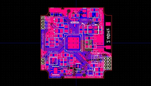
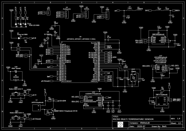
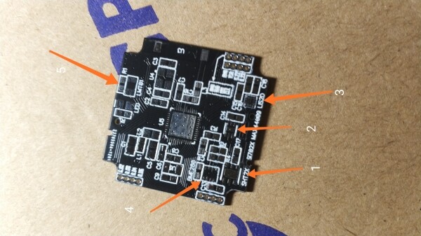
The following sensors were chosen for the sensor: SHT20, SHt21, Si7020, Si7021, HTU21D (temperature and humidity sensor); all of these sensors have the same housing and pinout. The HDC2080 (temperature and humidity sensor) also has a similar housing to the previously mentioned ones but includes an additional interrupt output and is more energy-efficient. The BME280 (temperature, humidity, and pressure sensor), LMT01 (temperature sensor), and TMP117 (high-precision temperature sensor) all feature high energy efficiency, interrupt output, and upper and lower temperature limit settings. Additionally, there is the LIS2DW12 (accelerometer) with high energy efficiency, which is among the best in its segment, or the LIS2DH12.
The first version of the sensor also included a reed switch, but it was removed in subsequent revisions because the 1.6 cm reed switch's glass bulb lacked space. I also broke a couple of these sensors while installing the finished board in the case. Furthermore, due to the square shape and short height of the case, the device was not very suitable for a magnetic opening and closing sensor.
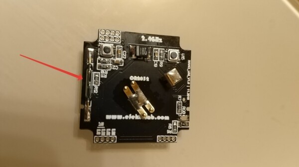
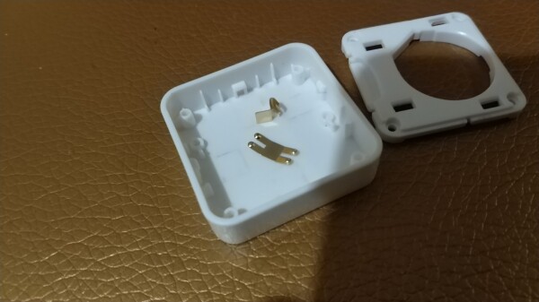
In addition to the sensors, the device features two LEDs, one of which is an RGB LED located on the underside of the sensor. There are two SMD buttons: one connected to reset, and the other a 'user' button for implementing some operating scenarios of the sensor. The sensor housing consists of three parts: the main case, an internal insert with a hole to hold the battery secured to the main case with four screws, and a lower cover that snaps into holes on the internal insert. It also has four analog pins, two digital pins, and two additional pins that can serve as an NFC antenna or digital pins, along with an SWD port.
The RGB LED and buttons are placed on the PCB in such a way that they are easily accessible when the lower cover is removed through holes in the internal insert, which are designed for securing the back cover.
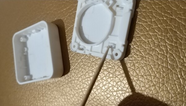
The device has survived two revisions; previously, the TMP117 sensor was replaced by the MAX44009 light sensor, which was later substituted back with a temperature sensor. Both sensors share the same housing but have different pin configurations. It might have been a mistake to replace the sensor, and it could be worth considering reverting to the old setup.
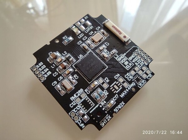
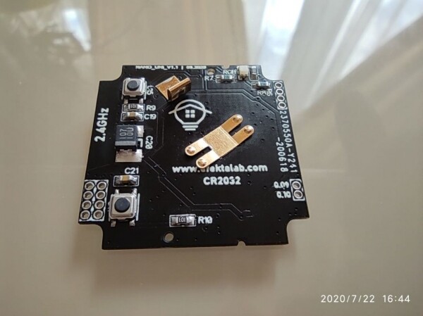
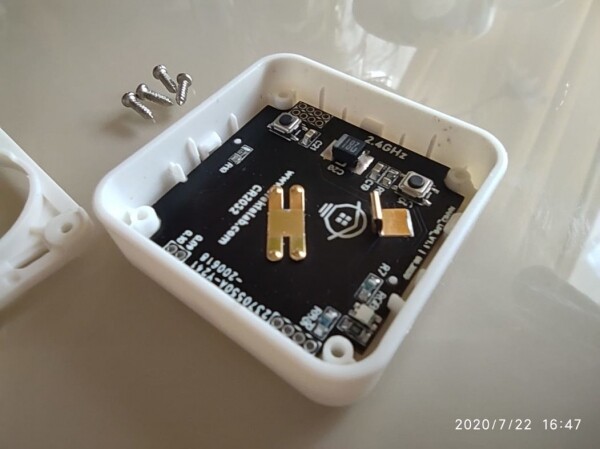
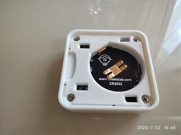
Currently, I have 4 such devices working at home, two of which are temperature and humidity sensors with Si7021 sensors (one on nRF52832, the other on nRF52811), one is an impact sensor implemented on the LIS2DW12 accelerometer (nRF52810), and a temperature monitoring sensor using the LMT01 sensor (nRF52810).
The wireless sensor operates on a cr2032 battery, consuming 1.8μA in sleep mode for nRF52810 and nRF52811, and 3.7μA for nRF52832. The data transmission mode consumes 8mA.
A description of the protocol used and software development for this sensor under different usage scenarios is probably beyond the scope of this article.
You can watch a test of the sensor working with the smart home system in the small video below.

The project for this sensor is open-source, and you can find all project materials on my .
If you are interested in everything related to DIY, whether you are a DIY developer or just want to start, and are interested in using DIY devices, I invite all interested to the .
For those who want to create devices and start building their home automation, I suggest getting acquainted with the easy-to-master Mysensors protocol — Telegram chat
And for those looking for more mature solutions for home automation, I invite you to the Telegram chat . ()
Thank you for your attention, wishing you all the best!
Source: habr.com
