

This video shows: the Raspberry Pi 3 board, which is connected via the GPIO port to the FPGA board Mars Rover 2rpi (Cyclone IV), and an HDMI monitor connected to it. A second monitor is connected through the standard HDMI port of the Raspberry Pi 3. Together, they operate as a dual-monitor system.
Next, I will explain how this is implemented.
The popular Raspberry Pi 3 board has a GPIO port that allows various expansion boards to be connected: sensors, LEDs, stepper motor drivers, and much more. The specific function of each pin on the port depends on the port configuration. The GPIO ALT2 configuration allows you to switch the port to the DPI interface mode, the Display Parallel Interface. There are expansion boards available for connecting VGA monitors through DPI. However, firstly, VGA monitors are not as common as HDMI anymore, and secondly, the digital interface is increasingly preferred over the analog one. Moreover, the DACs on such VGA expansion boards are typically based on R-2-R ladders and often have no more than 6 bits per color.
In ALT2 mode, the GPIO port pins have the following values:
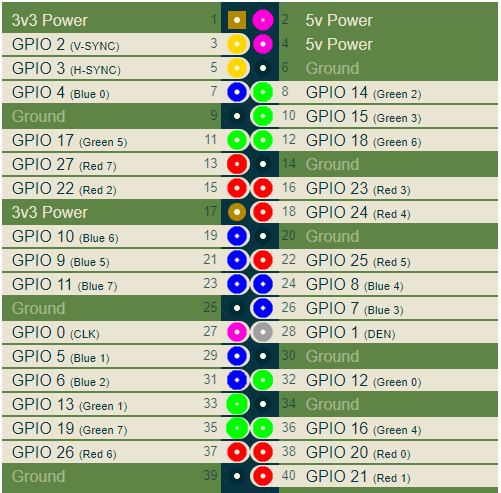
I here colored the RGB output pins accordingly in red, green, and blue colors. Other important signals include the vertical and horizontal synchronization signals V-SYNC and H-SYNC, as well as CLK. The clock frequency CLK is the frequency at which pixel values are output to the port, depending on the selected video mode.
To connect a digital HDMI monitor, it is necessary to capture the DPI interface signals and convert them into HDMI signals. This can be done, for example, using some FPGA board. It turns out that the Mars Rover 2rpi board is suitable for these purposes. To be honest, the primary way to connect this board via a special adapter looks like this:
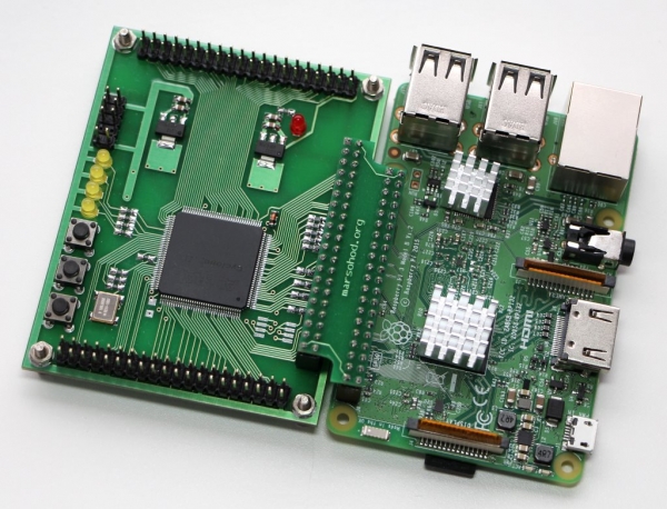
This board is used to increase the number of GPIO ports and to connect more peripheral devices to the Raspberry. However, 4 GPIO signals in this connection are used for JTAG signals, so the program from the Raspberry can load the FPGA firmware into the FPGA. Because of this, this standard connection does not work for me, as 4 DPI signals are lost. Fortunately, the additional headers on the board have a pinout compatible with Raspberry. So, I can rotate the board 90 degrees and still connect it to my Raspberry Pi:
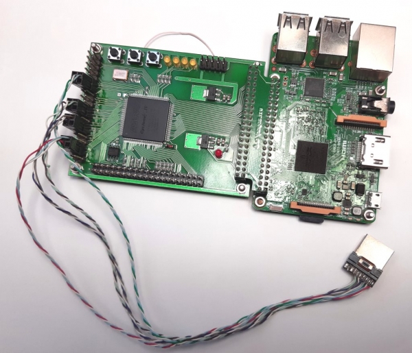
Of course, I will need to use an external JTAG programmer, but that’s not a problem.
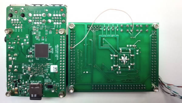
There is still a minor issue. Not every FPGA output can be utilized as a clock frequency input. There are only a few dedicated pins that can be used for this purpose. As a result, the GPIO_0 CLK signal does not reach the FPGA input that can be used as a clock frequency input. Therefore, I had to connect a wire to the board. I connect GPIO_0 and the signal KEY[1] of the board:
Now, I will talk a bit about the FPGA project. The main difficulty in generating HDMI signals is the very high frequencies involved. If you look at the HDMI connector pinout, you can see that the RGB signals are now sequential differential signals:
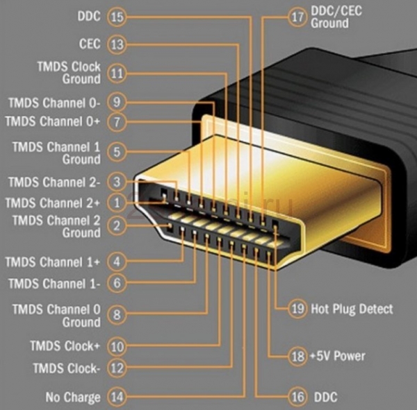
Using a differential signal helps to combat common-mode noise on the transmission line. In this case, the original 8-bit code of each color signal is transformed into a 10-bit TMDS (Transition-minimized differential signaling). This is a special encoding method to remove the DC component from the signal and minimize signal switching in the differential line. Since 10 bits must be transmitted across the serial transmission line for each color byte, the clock frequency of the serializer must be 10 times higher than the pixel clock frequency. For example, in the 1280×720 @ 60Hz video mode, the pixel frequency is 74.25MHz. The serializer must operate at 742.5MHz.
Unfortunately, standard FPGAs are generally not capable of this. However, fortunately, the FPGA has built-in DDIO outputs. These outputs act as 2-to-1 serializers, meaning they can output two bits sequentially on the rising and falling edges of the clock frequency. Therefore, in the FPGA project, you can use 370MHz instead of 740MHz, but you need to activate the DDIO output elements in the FPGA. A frequency of 370MHz is quite achievable. Unfortunately, the 1280×720 mode is the limit. Higher resolutions cannot be achieved on our Cyclone IV FPGA installed on the Mars Rover2rpi board.
So, in the project, the incoming pixel frequency CLK goes to the PLL, where it is multiplied by 5. At this frequency, the bytes R, G, B are converted into pairs of bits. This is done by the TMDS encoder. The original code in Verilog HDL looks like this:
module hdmi(
	input wire pixclk,		// 74MHz
	input wire clk_TMDS2,	// 370MHz
	input wire hsync,
	input wire vsync,
	input wire active,
	input wire [7:0]red,
	input wire [7:0]green,
	input wire [7:0]blue,
	output wire TMDS_bh,
	output wire TMDS_bl,
	output wire TMDS_gh,
	output wire TMDS_gl,
	output wire TMDS_rh,
	output wire TMDS_rl
);

wire [9:0] TMDS_red, TMDS_green, TMDS_blue;
TMDS_encoder encode_R(.clk(pixclk), .VD(red  ), .CD({vsync,hsync}), .VDE(active), .TMDS(TMDS_red));
TMDS_encoder encode_G(.clk(pixclk), .VD(green), .CD({vsync,hsync}), .VDE(active), .TMDS(TMDS_green));
TMDS_encoder encode_B(.clk(pixclk), .VD(blue ), .CD({vsync,hsync}), .VDE(active), .TMDS(TMDS_blue));

reg [2:0] TMDS_mod5=0;  // modulus 5 counter
reg [4:0] TMDS_shift_bh=0, TMDS_shift_bl=0;
reg [4:0] TMDS_shift_gh=0, TMDS_shift_gl=0;
reg [4:0] TMDS_shift_rh=0, TMDS_shift_rl=0;

wire [4:0] TMDS_blue_l  = {TMDS_blue[9],TMDS_blue[7],TMDS_blue[5],TMDS_blue[3],TMDS_blue[1]};
wire [4:0] TMDS_blue_h  = {TMDS_blue[8],TMDS_blue[6],TMDS_blue[4],TMDS_blue[2],TMDS_blue[0]};
wire [4:0] TMDS_green_l = {TMDS_green[9],TMDS_green[7],TMDS_green[5],TMDS_green[3],TMDS_green[1]};
wire [4:0] TMDS_green_h = {TMDS_green[8],TMDS_green[6],TMDS_green[4],TMDS_green[2],TMDS_green[0]};
wire [4:0] TMDS_red_l   = {TMDS_red[9],TMDS_red[7],TMDS_red[5],TMDS_red[3],TMDS_red[1]};
wire [4:0] TMDS_red_h   = {TMDS_red[8],TMDS_red[6],TMDS_red[4],TMDS_red[2],TMDS_red[0]};

always @(posedge clk_TMDS2)
begin
	TMDS_shift_bh <= TMDS_mod5[2] ? TMDS_blue_h  : TMDS_shift_bh  [4:1];
	TMDS_shift_bl <= TMDS_mod5[2] ? TMDS_blue_l  : TMDS_shift_bl  [4:1];
	TMDS_shift_gh <= TMDS_mod5[2] ? TMDS_green_h : TMDS_shift_gh  [4:1];
	TMDS_shift_gl <= TMDS_mod5[2] ? TMDS_green_l : TMDS_shift_gl  [4:1];
	TMDS_shift_rh <= TMDS_mod5[2] ? TMDS_red_h   : TMDS_shift_rh  [4:1];
	TMDS_shift_rl <= TMDS_mod5[2] ? TMDS_red_l   : TMDS_shift_rl  [4:1];
	TMDS_mod5 4'd4) || (Nb1s==4'd4 && VD[0]==1'b0);
wire [8:0] q_m = {~XNOR, q_m[6:0] ^ VD[7:1] ^ {7{XNOR}}, VD[0]};

reg [3:0] balance_acc = 0;
wire [3:0] balance = q_m[0] + q_m[1] + q_m[2] + q_m[3] + q_m[4] + q_m[5] + q_m[6] + q_m[7] - 4'd4;
wire balance_sign_eq = (balance[3] == balance_acc[3]);
wire invert_q_m = (balance==0 || balance_acc==0) ? ~q_m[8] : balance_sign_eq;
wire [3:0] balance_acc_inc = balance - ({q_m[8] ^ ~balance_sign_eq} & ~(balance==0 || balance_acc==0));
wire [3:0] balance_acc_new = invert_q_m ? balance_acc-balance_acc_inc : balance_acc+balance_acc_inc;
wire [9:0] TMDS_data = {invert_q_m, q_m[8], q_m[7:0] ^ {8{invert_q_m}}};
wire [9:0] TMDS_code = CD[1] ? (CD[0] ? 10'b1010101011 : 10'b0101010100) : (CD[0] ? 10'b0010101011 : 10'b1101010100);

always @(posedge clk) TMDS <= VDE ? TMDS_data : TMDS_code;
always @(posedge clk) balance_acc <= VDE ? balance_acc_new : 4'h0;

endmodule
Then the output pairs are fed to the DDIO output, which sequentially issues a one-bit signal on the rising and falling edges.
The DDIO itself could be described with the following Verilog code:
module ddio(
	input wire d0,
	input wire d1,
	input wire clk,
	output wire out
	);

reg r_d0;
reg r_d1;
always @(posedge clk)
begin
	r_d0 <= d0;
	r_d1 <= d1;
end
assign out = clk ? r_d0 : r_d1;
endmodule
However, this approach is unlikely to work. You need to use the alternative mega function ALTDDIO_OUT to actually engage the output DDIO elements. My project specifically uses the library component ALTDDIO_OUT.
It may seem a bit convoluted, but it works.
You can view the entire source code written in Verilog HDL .
The compiled firmware for the FPGA is flashed into the EPCS chip mounted on the Mars Rover2rpi board. Thus, when power is supplied to the FPGA board, the FPGA will initialize from flash memory and start up.
Now, let's discuss the configuration of the Raspberry itself.
I am experimenting with Raspberry PI OS (32 bit) based on Debian Buster, Version: August 2020,
Release date: 2020-08-20, Kernel version: 5.4.
You need to do two things:
- edit the config.txt file;
- create an X server configuration to work with two monitors.
When editing the file /boot/config.txt, you need to:
- disable i2c, i2s, spi usage;
- enable DPI mode using the overlay dtoverlay=dpi24;
- configure the video mode to 1280×720 at 60Hz, 24 bits per pixel on DPI;
- set the required number of framebuffers to 2 (max_framebuffers=2, only then will the second device /dev/fb1 appear)
The complete text of the config.txt file looks like this.
# For more options and information see
# http://rpf.io/configtxt
# Some settings may impact device functionality. See link above for details

# uncomment if you get no picture on HDMI for a default "safe" mode
#hdmi_safe=1

# uncomment this if your display has a black border of unused pixels visible
# and your display can output without overscan
disable_overscan=1

# uncomment the following to adjust overscan. Use positive numbers if console
# goes off screen, and negative if there is too much border
#overscan_left=16
#overscan_right=16
#overscan_top=16
#overscan_bottom=16

# uncomment to force a console size. By default it will be display's size minus
# overscan.
#framebuffer_width=1280
#framebuffer_height=720

# uncomment if hdmi display is not detected and composite is being output
hdmi_force_hotplug=1

# uncomment to force a specific HDMI mode (this will force VGA)
#hdmi_group=1
#hdmi_mode=1

# uncomment to force a HDMI mode rather than DVI. This can make audio work in
# DMT (computer monitor) modes
#hdmi_drive=2

# uncomment to increase signal to HDMI, if you have interference, blanking, or
# no display
#config_hdmi_boost=4

# uncomment for composite PAL
#sdtv_mode=2

#uncomment to overclock the arm. 700 MHz is the default.
#arm_freq=800

# Uncomment some or all of these to enable the optional hardware interfaces
#dtparam=i2c_arm=on
#dtparam=i2s=on
#dtparam=spi=on

dtparam=i2c_arm=off
dtparam=spi=off
dtparam=i2s=off

dtoverlay=dpi24
overscan_left=0
overscan_right=0
overscan_top=0
overscan_bottom=0
framebuffer_width=1280
framebuffer_height=720
display_default_lcd=0
enable_dpi_lcd=1
dpi_group=2
dpi_mode=87
#dpi_group=1
#dpi_mode=4
dpi_output_format=0x6f027
dpi_timings=1280 1 110 40 220 720 1 5 5 20 0 0 0 60 0 74000000 3

# Uncomment this to enable infrared communication.
#dtoverlay=gpio-ir,gpio_pin=17
#dtoverlay=gpio-ir-tx,gpio_pin=18

# Additional overlays and parameters are documented /boot/overlays/README

# Enable audio (loads snd_bcm2835)
dtparam=audio=on

[pi4]
# Enable DRM VC4 V3D driver on top of the dispmanx display stack
#dtoverlay=vc4-fkms-v3d
max_framebuffers=2

[all]
#dtoverlay=vc4-fkms-v3d
max_framebuffers=2
After that, you need to create a configuration file for the X server to use two monitors on two framebuffers /dev/fb0 and /dev/fb1:
My configuration file /usr/share/x11/xorg.conf.d/60-dualscreen.conf looks like this:
Section "Device"
        Identifier      "LCD"
        Driver          "fbturbo"
        Option          "fbdev" "\/dev\/fb0"
        Option          "ShadowFB" "off"
        Option          "SwapbuffersWait" "true"
EndSection

Section "Device"
        Identifier      "HDMI"
        Driver          "fbturbo"
        Option          "fbdev" "\/dev\/fb1"
        Option          "ShadowFB" "off"
        Option          "SwapbuffersWait" "true"
EndSection

Section "Monitor"
        Identifier      "LCD-monitor"
        Option          "Primary" "true"
EndSection

Section "Monitor"
        Identifier      "HDMI-monitor"
        Option          "RightOf" "LCD-monitor"
EndSection

Section "Screen"
        Identifier      "screen0"
        Device          "LCD"
        Monitor         "LCD-monitor"
EndSection

Section "Screen"
        Identifier      "screen1"
        Device          "HDMI"
	Monitor         "HDMI-monitor"
EndSection

Section "ServerLayout"
        Identifier      "default"
        Option          "Xinerama" "on"
        Option          "Clone" "off"
        Screen 0        "screen0"
        Screen 1        "screen1" RightOf "screen0"
EndSection
And if Xinerama is not yet installed, you need to install it. Then the desktop space will be fully extended across two monitors, as shown in the demo video above.
That's about it. Now, Raspberry Pi3 users can take advantage of dual monitors.
You can view the description and schematic of the Mars Rover 2rpi .
Source: habr.com
