

Good day, friends! Today I will continue the series dedicated to with an article on Enterprise network design.
In this article, I will try to be as concise as possible:
- to describe the modular approach to designing an Enterprise network
- to discuss the types of constructing one of the most important modules of an enterprise network— the core network (ip-campus)
- to outline the advantages and disadvantages of redundancy options for critical nodes in the network
- to design/update a small Enterprise network using an abstract example
- to choose Extreme switches for implementing the designed network
- to work with fibers and IP addressing
This article will be of more interest to network engineers and enterprise network administrators who are just starting their journey in networking rather than to experienced engineers who have worked for many years in telecommunications or in large corporations with geographically distributed networks.
In any case, those interested are invited to read further.
Modular Approach to Network Design
I will start my article with a rather popular modular approach in network design, which allows assembling the puzzle of a network into one complete picture.
First, a bit of abstraction—I often visualize this approach as zooming in on geo-maps, where at first glance, the country is visible, in the second, regions, in the third, cities, and so on.
As an example, consider the following:
- The first zoom level—the entire enterprise network represents a set of various levels:
- the core network or campus
- the border level
- the level of telecommunications operators
- remote zones
- The second zoom level—each of these levels is detailed into separate modules
- the core network or campus consists of:
- a 3-tier or 2-tier module describing the enterprise network and its levels—access, distribution, and/or core
- a module describing the data center (essentially the server part of the infrastructure)
- the border level, in turn, consists of:
- a module for internet connectivity
- a WAN and MAN module responsible for connecting geographically distributed enterprise objects
- a module for building VPN tunnels and Remote Access
- often, many small enterprises find that several of these modules or even all of them are combined into one
- the provider level:
- This level includes connections to the 'external world' — dark fiber optics (leasing fibers from operators), communication channels (Ethernet, G.703, etc.), Internet access.
- remote level:
- for the most part, these are the branches of the company distributed across the city, region, country, or even continents.
- also, this zone may include a backup data center that duplicates the work of the main one.
- and of course, the increasingly popular teleworkers (remote workplaces)
- the core network or campus consists of:
- The third approach — each of the modules is broken down into smaller modules or levels. For example, in a campus network:
- The three-tier network is divided into:
- access layer
- distribution layer
- core layer
- In more complex cases, the data center may be divided into:
- a two-tier or three-tier network part
- server part
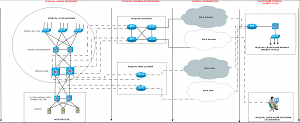
I will attempt to illustrate everything described above in the following simplified diagram:

As can be seen from the diagram above — the modular approach helps to detail and structure the overall picture into components that can then be worked with.In this article, I will focus on the Campus Enterprise level and describe it in more detail.
Types of IP-CAMPUS networks
During my time working at a provider and especially later as an integrator, I encountered varying 'maturity' of client networks. I use the term maturity deliberately, as there are frequent cases where the network structure grows with the company itself, which is quite natural.
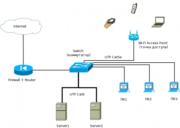
In a small company located within a single building, the enterprise network may consist of just one edge router serving as a firewall, several access switches, and a couple of servers.
I refer to such a network as a 'single-tier' network — it completely lacks a distinct core network layer, the distribution layer is shifted to the edge router (with firewall, VPN, and possibly proxy functions), and the access switches serve both employee computers and servers.

In the event of company growth — an increase in the number of employees, services, and servers, it often becomes necessary to:- increase the number of switches in the network and access ports
- increase server capacities
- fighting against broadcast domains — implementing network segmentation and routing between segments
- combating network failures that cause employee downtime, as this results in additional financial costs for management (employees are idle, salary is paid, but work isn't done)
- in the process of addressing failures, considering redundancy for critical network nodes — routers, switches, servers, and services
- tightening security policies, as commercial risks may arise, and again — for more stable network performance
All of this leads to the network engineer (administrator) inevitably thinking about the proper network architecture, arriving at a two-tier model.
This model clearly distinguishes two levels — the access layer and the distribution layer, which also serves as the core level (collapsed-core).
The combined distribution and core layer performs the following functions:
- aggregates links from access switches
- introduces routing for network segments — users and devices become so numerous that a single /24 network cannot accommodate them, and if they do fit, broadcast storms cause constant failures (especially when users create loops)
- provides connectivity between adjacent segments of switches (over faster links)
- ensures communication between users and their devices and the server farm, which by that time also begins to be separated into a distinct network segment — the data center.
- begins to jointly enforce, along with access switches, a security policy that is starting to emerge at the enterprise level. The company is growing, and commercial risks are also increasing (here I'm referring not only to confidentiality agreements, access policy delineation, etc., but also to basic network and employee downtimes).
Thus, the network eventually evolves into a two-tier model:

This model introduces specific requirements for access layer switches that aggregate connections from users and network devices (printers, access points, VoIP devices, IP phones, IP cameras, etc.), as well as for distribution and core switches.Access switches need to be more intelligent and functional to meet network performance, security, and flexibility requirements. They should:
- have various types of access and trunk ports — ideally with capacity for traffic growth and additional ports
- have sufficient switching capacity and bandwidth
- have necessary security functionalities that comply with current security policies (and ideally adapt to any future requirements)
- have the capability to power inaccessible network devices with the option for remote power cycling (PoE, PoE+)
- have a way to back up its own power supply for use in areas where necessary
- have, if possible, further potential for functional growth — a common example is when an access switch gradually becomes a distribution switch
Corresponding requirements also apply to distribution switches:
- regarding trunk downward ports towards access switches, as well as towards peer interfaces of neighboring distribution switches (and potentially upstream interfaces towards the core later)
- in terms of L2 and L3 functionalities
- in terms of security functionality
- in terms of ensuring fault tolerance (redundancy, clustering, and power supply backup)
- in terms of providing flexibility in traffic balancing
- have, if possible, further potential for functional growth (transforming over time from aggregation to core devices)
- in some cases, it may be appropriate to use PoE, PoE+ ports on distribution switches.
Going forward, if the management implements an active growth and development policy for the business, the network will continue to evolve — the company may begin renting neighboring buildings, constructing its own facilities, or acquiring smaller competitors, thereby increasing the number of jobs for employees. At the same time, the growth of the network also necessitates:
- providing employees with workspaces — new access switches with access ports are required
- the presence of new distribution switches to aggregate links from access switches
- the construction of new and the modernization of existing communication lines
As a result, traffic increases for the following reasons:
- due to an increase in access ports and, accordingly, network users
- due to the increase in traffic from adjacent subsystems that select the company's network as transport — telephony, security, engineering systems, etc.
- due to the implementation of additional services — as the staff grows, new departments emerge that require specific software
- the computing power of the data center is increasing to meet the demands of the infrastructure and applications
- security requirements for the network and information are growing — the famous CIA triad (just kidding), but seriously, CIA stands for Confidentiality, Integrity, and Availability:
- in this context, additional requirements for fault tolerance and redundancy arise for critical network levels — distribution and data centers
- again, traffic grows due to the implementation of new security systems — for example, RKVIs, etc.
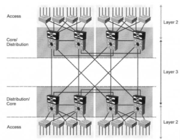
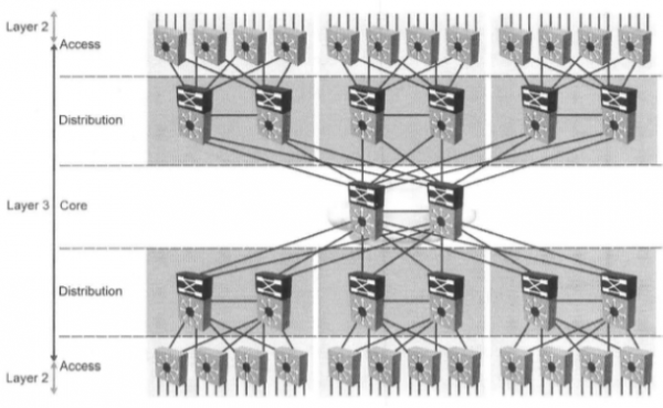
Sooner or later, the increase in traffic, services, and the number of users will necessitate the introduction of an additional network layer — the core, which will perform high-speed switching/routing of packets using high-speed communication links.
At this point, the company can transition to a three-tier network model:

As shown in the figure above — such a network includes a core layer that aggregates high-speed links from distribution switches. Thus, core switches also have requirements regarding:- interface bandwidth — 1GE, 2.5GE, 10GE, 40GE, 100GE
- switching capacity and forwarding performance
- interface types — 1000BASE-T, SFP, SFP+, QSFP, QSFP+
- the number and set of interfaces
- redundancy capabilities (stacking, clustering, management plane redundancy (relevant for modular switches), power supply redundancy, etc.)
- functionality
At this network level, both its technical modifications are definitely necessary:
- node and core link redundancy (very, very, very desirable)
- node and distribution link redundancy (depending on criticality)
- redundancy of links between access switches and the distribution layer (as needed)
- introduction of dynamic routing protocols
- traffic balancing both in the core and at the distribution and access layers (if necessary)
- implementation of additional services — both transport and security services (if necessary)
as well as legal, defining the enterprise's network security policy, which complements the overall security policy in terms of:
- requirements for the implementation and configuration of various security features on access and distribution switches
- requirements for access, monitoring, and management of network equipment (remote access protocols, permitted segments for network management, logging settings, etc.)
- requirements for redundancy
- requirements for forming a minimally necessary ZIP kit
In this section, I briefly described the evolution of the network and enterprise from a few switches and a couple of dozen employees to several dozen (or maybe even hundreds of switches) and several hundred (or even thousands) of those employees who directly work within the enterprise network (and there are also production departments and engineering networks).
It is clear that in reality, such 'miraculous' and rapid development of an enterprise does not occur.
It usually takes years for an enterprise and network to grow from their initial level 1 to the 3rd level I am describing.Why am I writing all these obvious truths? Because I want to mention a term like ROI — return-on-investment and consider that aspect which directly concerns the choice of network equipment.
When choosing equipment, network engineers and their managers often select gear based on two factors: the current price of the equipment and the minimal technical functionality required at that moment to solve specific tasks (I will discuss the purchase of equipment for redundancy later).
At the same time, the potential for future 'growth' of the equipment is rarely considered. When a situation arises where the equipment has exhausted its functionality or performance, more powerful and functional gear is then purchased, while the old one is either stored in a warehouse or repurposed in the network on the principle of 'just letting it sit' (this, by the way, also contributes to the emergence of a large zoo of equipment and the acquisition of numerous information systems that work with it).
Thus, instead of buying additional licenses for extra functionality and performance, which are much cheaper than new high-performance equipment, it becomes necessary to purchase new hardware and overpay for the following reasons:
- the network often grows slowly, and expanding the functionality or performance of your network's switches can last for a long time
- It's no secret that equipment from foreign vendors is tied to foreign currency (dollars or euros). To be honest, the rise of the dollar or euro (or periodic mini-devaluation of the ruble, depending on the perspective) means that a dollar ten years ago and a dollar now are completely different in terms of rubles.
In summary, I would like to note that purchasing network equipment with broader functionality now can lead to savings in the future.
Here, I consider the costs of purchasing equipment in the context of investing in my network and infrastructure.Thus, many vendors (not just Extreme) adhere to the principle of pay-as-you-grow, embedding a multitude of features and performance enhancement capabilities into the equipment, which are later activated by purchasing separate licenses. They also offer modular switches with a wide range of interface and processor cards, with the capability to sequentially increase both their quantity and performance.
Critical Node Redundancy
In this section of the article, I would like to briefly outline the fundamental principles of reserving crucial network nodes, such as core switches, data centers, or distribution points. I will start by discussing the general types of redundancy—stacking and clustering.
Each of these methods has its advantages and disadvantages, which I would like to discuss.
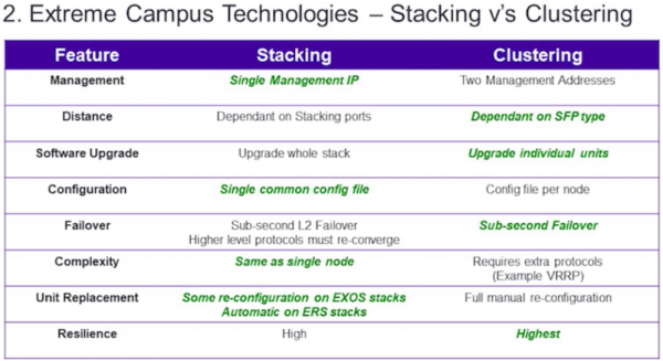
Below is a general summary table comparing the two methods:

- management — as seen from the table, stacking has the advantage in terms of management since a stack of multiple switches appears as a single switch with a larger number of ports. Instead of managing, for example, eight different switches in a cluster, you can manage just one when stacking.
- distance — currently, strictly speaking, the advantage of clustering is not so obvious, as stacking technologies have emerged using stacking ports or dual-purpose ports (such as SummitStack-V at Extreme, VSS at Cisco, etc.), which also depend on the types of transceivers. Here, the preference is given to clustering based on the principle that with stacking, there are options that require the use of standard stacking ports, which are often connected with special cables of limited length—0.5, 1, 1.5, 3, or 5 meters.
- software update — here we see that clustering has an advantage over stacking because when updating the equipment's software version in a stack, you update the software on the master switch, which then takes on the role of deploying the new software to the standby member switches of the stack. On one hand, this simplifies your work, but updating the software often requires a hardware reboot of the equipment, which leads to the rebooting of the entire stack, and consequently, a disruption in its operation and all services dependent on it for the duration of the reboot. Typically, this is very critical for the core and data centers. In clustering, you have two independent devices on which you can update the software sequentially. This allows you to avoid service interruptions.
- settings configuration — here, the advantage definitely lies with stacking, as in this case, you only need to modify the settings for one device and its configuration file. In clustering, however, the number of configuration files will equal the number of nodes in the cluster.
- fault tolerance — in this case, both technologies are approximately equal, but clustering still has a slight advantage. The reason lies in the following: if we look at the stack from the perspective of running processes and protocols, we will see the following:
- there is a master switch on which all main processes and protocols run (for example, the dynamic routing protocol — OSPF)
- there are other slave switch switches on which the main processes needed for operation in the stack and servicing the traffic passing through them run
- when the master switch fails, the next highest priority slave switch detects the master's failure
- it initiates itself as the master and starts all processes that were running on the master (including the OSPF protocol we observed)
- after a certain period of process startup time (usually quite short), the OSPF protocol itself begins to work
- thus, OSPF will respond a little faster to the failure of a node in clustering than in stacking (during the time required to start and initialize the processes and protocols on the slave switch of the stack). However, I should note that modern stacking protocols and switches respond very quickly; often, the duration of traffic interruption during stack switchovers takes less than a second, but nominally, clustering wins on this parameter.
- complexity — as can be seen from the table, stacking wins in terms of complexity. This is a direct consequence of the 'management' and 'configuration settings' points. A single node takes much less time for settings and management. Also, in clustering, it is quite common to have to configure additional routing protocols or gateway redundancy protocols — VRRP, HSRP, and others.
- replacement of nodes Here, the advantage lies clearly with stacking. Often, to replace a switch in a stack, minimal necessary equipment settings must be configured, for example:
- updating the new switch's firmware to the stack's software version (which can be done immediately upon the switches arriving at the warehouse)
- setting up several basic commands for stacking (and for some types of switches, this might not even be required)
- removing the failed stack switch and connecting a new one
- connecting power and patch cords
- resilience I consider resilience to be one of the key parameters. In general, resilience is a comprehensive characteristic that refers to the property of something to change under load and return to its original state after the load is removed. Surprisingly, for clustering, it will be higher even with a 4:3 score in favor of stacking characteristics. It's all about the human factor. Yes, don't be surprised—it's in the strength of such stacking parameters as unified management, configuration settings, and reduced complexity that the weakness of stacking lies, when the human factor comes into play.
In my IT career, I've encountered situations many times (and to be honest, I've stumbled upon the same pitfalls myself, especially in the beginning) where, while setting up a stack, an engineer made mistakes in entering certain commands or in enabling/disabling particular features on the equipment, which led to the entire stack failing and needing a manual restart. It's worth mentioning the fans of the Putty application for Windows (oh, the joy of copying with the right mouse button).
In reality, both technologies are quite good (especially compared to the lack of redundancy), and each has its strengths and weaknesses, but for core level and high-load data centers, I would still prefer to use clustering.
Though this is just my opinion. Many professional engineers who have been supporting networks at a professional level for many years can competently use both technologies—here, it all depends on experience and qualifications.
In addition to the technologies of stacking and node network redundancy, there are also general principles for reserving parts of the node itself and the connections between nodes:
By redundancy within a network node, I mean:
- power supply redundancy — installing 2 power supplies that duplicate each other (preferably connected to the primary power supply category) can greatly ease your workload.
- control board redundancy — mostly pertains to modular switches, which are designed to connect multiple redundant control boards.
- redundancy of interface cards — also mainly refers to modular switches.
Redundancy of connections/links mainly includes having duplicate cable routes (or radio links in open spaces) with:
- distribution across different cable shafts and channels within a building
- geographical distribution across territories at the level of 2 or more buildings, cities, regions, or countries (so-called volumetric rings)
When constructing redundant communication links, it is necessary to follow a number of equipment recommendations:
- in the case of duplicating interface cards of a modular switch, or when stacking exists, it is essential to distribute the links between units — interface cards in the case of modular switches and switches in the case of a stack.
- it is advisable to use link aggregation protocols (LACP, MLT, PAgP, etc.) to group links and balance the load among them.
- use routers that support ECMP (Equal-Cost-Multi-Path) protocols — when delivering multiple packets via one route, these packets do not go through a single best path (and interface) but are distributed across several best-paths (and several interfaces), determined by equal routing protocol metrics, which is responsible for populating the final routing table.
Now, as promised, I will describe a real case from my experience and the principle of saving when reserving critical nodes that happened a few years ago:
- in one company, which I will call X, there was a standard 3-tier network model:
- with several cores
- and several dozen aggregations
- thousands of access switches
- tens of thousands of users
- the network was quite complex to build:
- with a bunch of dynamic routing protocols and protocols — OSPF, MP-BGP, MPLS, PIM, IGMP, IPv6, etc.
- a bunch of services — internet access, L2 and L3 VPN, VoIP, IPTV, dedicated lines, etc.
- but there was one bottleneck in the network — the border router, which combined the functions of a BGP border and terminated some user services
- yes, it cost as much as an airplane wing (several million rubles)
- yes, at that time it was one of the top devices in the lineup of the most renowned network vendor
- yes, it had to be very reliable — with an excellent MTBF
- yes, it had 4 power supplies configured in a 2x2 scheme and connected to different UPS systems and inputs.
But all this did not change the fact that it was a single point of failure in the network.
And one day, far from wonderful for me and my colleagues, this router went down (later it was found that there was some failure on the power line through the UPS, which led to the simultaneous failure of 2 power supplies, and one of the units burned out the RP module of the router and the interface card connected to the device's common data bus).
We did not have spare boards — RP and interface cards, but we had a contract for equipment replacement or its components with one of the partners under the NBD scheme.
Unfortunately, the partners only had the interface card in stock at that time, but the RP board was not available, it only arrived a few days later (in 3 days).
As a result, the presence of a single point of failure in the network (even with a support and equipment replacement contract) led to the following financial costs:
- the share of services of the company associated with or related to this border amounted to about 60-70%
- as calculated later, the daily profit was around 900 thousand rubles (approximately) at that time
- thus, for 3 days of downtime, theoretically, the profit lost amounted to between 1 million 620 thousand rubles and 1 million 890 thousand rubles
Of course, the net losses were smaller, as compensation for the main part of the users was returned not in cash, but in the form of services, but they still existed:
- part of the compensation to corporate users
- increased costs for company employees who worked all these 3-4 days in full force — overtime, night shifts, increased shifts, etc.
- reputational losses, which are also quite significant
- and most importantly — the nerves of both management and employees, as well as clients
As a result, the company's policy was revised:
- canceled the replacement contract under the NBD condition
- retained the standard service contract
- purchased a backup router costing approximately 1 — 1.3 million rubles to reserve 90% of the main functionality
In the future, the purchase of additional equipment and reserving the main one allowed balancing the load between them for external links, traffic, and users, providing a safety margin for the company in case of future emergencies.
Example of Enterprise Network Design
In this part of the article, I will try to outline the main points in calculating the backbone network of the enterprise. I will not overload you with the entire methodology of PPDIOO (Prepare-Planning-Design-Implement-Operate-Optimize), but will only highlight its key points:
- Prepare — you need to agree with your management on the goals of network modernization that you want to achieve — increase fault tolerance, implement new services or technologies. I will skip the identification of constraints — both technical and organizational, as I assume you are an employee of the organization and have ample time to overcome them. I will return to the budget issue below.
- Planning — here you should build a complete characterization of your current network (if you are not already familiar with it), that is, describe the network as it currently exists:
- the number and type of equipment
- the number and types of ports
- existing cable paths and switching schemes inside buildings and between them
- power supply schemes
- L2 and L3 addressing
- build Wi-Fi network maps indicating access points and controllers
- describe your server farm
- ideally, describe all your services and connections between them
- if you already have some form of network security policy and network access restrictions implemented, make sure to consider it during the design
- First, I should mention that the second step essentially involves a complete inventory of the network, starting from the cabling infrastructure and power schemes to the services (applications and their ports). This step is very, very labor-intensive and can sometimes be tedious. If you or your predecessor did not keep documentation or even a basic monitoring system, now is the time to consider it. Networks tend to change over time at varying speeds, and only maintaining up-to-date documentation or a monitoring system can help you keep track of its state and ease its administration. But that pertains to the operate step.
- Design Equipped with complete knowledge of your network acquired in the previous step, you finally sit down and think about how to upgrade your network. Below, I will demonstrate a small example of network calculation.
I have compiled a small list of initial data that I will use in the calculation and design of the backbone network.
Let's represent the Prepare step as a list of what we have available and what is planned to be done:
- There is quite a large enterprise with approximately 700-800 workstations (here I mean those employees who require access to the company's network)
- There are several standalone buildings within the enterprise's territory:
- Main buildings:
- Number of buildings – 2
- Number of floors in the building – 7
- Number of telecom cabinets per floor in one building – 3 (total 21)
- Number of employees in the building =~ 250 people
- Additional buildings:
- Number of buildings – 10
- Number of floors in the building/workshop – 2
- Number of telecom cabinets in the building – 3
- Number of employees in the building =~ 20 people
- Current core network level (by the way, a very common scheme that I have encountered many times in one form or another and port configuration) is represented by:
- 2 L2 switches:
- 1Gb RJ-45 ports – 24
- 1Gb SFP ports – 4
- 1 L2 switch:
- 1Gb SFP ports – 24
- Core topology – ring
- Peer-to-peer links between switches are connected using optical fibers
- Switches are located in small server rooms with cabinets
- 2 L2 switches:
- Current distribution level:
- merged with the core network level in terms of link aggregation from access switches
- L3 addressing is offloaded to the border router and/or firewall
- Current access level:
- L2 switches with 16 x 100 Mb RJ-45 access ports and 2 gigabit combo uplink RJ-45/SFP ports
- switches are located in cabinets on the floors
- access switch topology:
- star (hub-and-spoke) with a core/distribution switch in the center
- branch/spoke consists of a chain of 3 switches on the floors
- there are unmanaged access switches
- switches in 9 additional enclosures are connected via media converters (optical to electrical signal converters)
- Current cable infrastructure:
- Cable system between buildings:
- there is an optical cable between the two main buildings with a capacity of 8 fibers
- there is 1 optical cable between one of the additional enclosures (where the core switch is installed) and each of the main buildings with a capacity of 8 fibers each
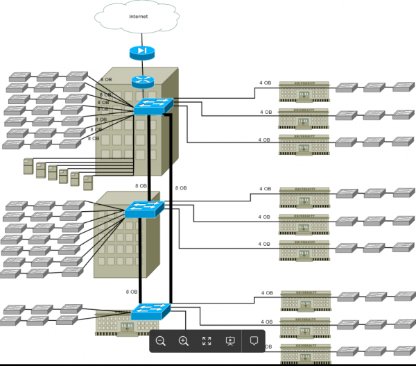
- there is 1 optical cable between additional enclosures and enclosures with installed core switches with a capacity of 4 fibers (their distribution is shown in the picture below)
- fiber type in all cables - single-mode/SMF
- 2-fiber single-mode SFP transceivers are used
- some cables are terminated on optical distribution frames (ODF) in separate rooms (cross-connect rooms/server rooms), while some cables are in floor racks
- Cable system inside buildings:
- there is a mixed cable structure between server rooms and the first racks on the floors:
- Cat5e copper cables - 10 pcs (or 100 pair cables)
- multimode/MMF optical cable with 4 or 8 fibers - 1 pc
- multimode/MMF optical cable with 4 fibers between floor racks
- Cat5e copper cables between floor racks and access sockets
- current data center:
- there are several servers, for example, 6 units
- connected via 1Gb ports to the core switch in the 1st main building
- all enterprise applications are hosted on servers
- L2, L3 addressing and routing:
- the network contains several VLANs - 2 or 3 per building
- servers are allocated in a separate /24 network
- for internal needs, gray Class B networks within the range — 172.16.0.0/16 are used
- L3 addresses are terminated at the edge router and/or firewall.
- static routing is used.
- additional information:
- telephony:
- traditional telephony using old-style digital PBXs (not IP-PBX) is deployed in buildings and some sections.
- it is necessary to provide telephony for new buildings without incurring costs for laying expensive copper cable lines of a specific capacity and building a redundant structured cabling system for telephony inside buildings.
- over time, it is planned to introduce IP telephony throughout the enterprise, integrating it with CRM systems and transitioning all employees to it.
- port capacity:
- it is necessary to analyze the current capacity of trunk ports and access ports, reserving at least 25-30% for future needs.
- analyze the sufficiency of the current bandwidth of access ports and trunk links.
- consider the availability of PoE/PoE+ access ports for devices from adjacent systems — video surveillance and telephony.
- video surveillance:
- it is planned to use the enterprise network as a transport for the video surveillance network.
- it is necessary to provide for the availability of PoE ports for surveillance cameras.
- wireless systems:
- it is planned to implement a wireless infrastructure in the future for employee mobility.
- it is necessary to provide for the availability of PoE ports for access points.
- budget, timelines, and equipment requirements:
- maximize the use of existing equipment.
- when designing the network, consider the possibility of expanding network bandwidth for N years ahead.
- when designing the network, consider support for all possible security functions — here is a list of functionalities ranging from port security to user authentication and authorization via 802.1x.
- reserve critical network nodes of primary importance as much as possible — core and data center, and consider the possibility of reserving secondary importance nodes — distribution nodes.
- the project budget must provide for continuous financing in several phases.
- the budget amount — each enterprise determines this based on its own financial indicators.
- In the ideal case, there will be no explicit deadlines, as this is an internal company project implemented by its own employees, or the deadlines will be relatively comfortable— for example, 1 year (or more). In a worse case, it can range from 3 months to half a year.
- Address current network issues:
- Packet loss
- Issues with DHCP on more or less intelligent access switches related to the use of the STP protocol family to combat loops on access ports.
- Eliminate the presence of a DHCP server interface in each VLAN for employees.
- Occurrence of switching loops related to unauthorized connections of managed/unmanaged switches in offices and the connection of various devices to them.
- The list can go on and on...
Step Planning—characterizing the state of your current network, as I have mentioned, depends on the existence of a quality monitoring system and the degree of its documentation. At this step, you will need to:
- At a minimum, sketch out the existing network for further analysis.
- Collect data from the equipment:
- Traffic on backbone ports
- Errors on ports
- CPU load and memory usage on switches and routers
- Detail L2-L3 diagrams by VLANs and IP addresses.
- Raise cabling route diagrams:
- Fiber optic diagrams and wiring diagrams for optical cross-connections.
- Copper cabling distribution diagrams between server rooms and floors.
- Copper cabling distribution diagrams between floors and offices.
- Check the presence of optical cross-connects and patch panels in server rooms and cabinets.
- Check power supply diagrams in server rooms and floor cabinets.
- Check the presence of UPS and batteries at critical nodes.
- Analyze all the data.
Based on the data from the preparation stage, I created an approximate logical diagram:

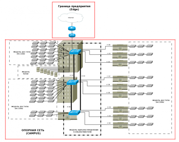
Next, following the modular approach, it is necessary to identify the levels and modules of the enterprise:
I will not address the boundaries (Edge) in this article, but I will briefly remind the basic theses for each module of the Campus:- Access—at this level should provide:
- The necessary number of ports for user access to the network.
- Implementation of security policies—traffic and protocol filtering.
- Broadcast domain compression and network segmentation using VLAN.
- implementation of separate VLANs for voice traffic
- support for QoS
- support for PoE access ports
- support for IP multicast
- redundancy of uplink connections together with the distribution level (preferably)
- The distribution level must ensure:
- the necessary number of ports for connecting access switches
- aggregation and redundancy of access switch links
- IP routing
- packet filtering
- support for QoS
- redundancy at the link, equipment, and power level (highly desirable)
- The core must ensure:
- high speed of packet switching and routing
- the necessary number of ports for connecting distribution switches
- support for IP routing and dynamic routing protocols with fast network convergence
- support for QoS
- security functionality to protect access to equipment and the control plane
- redundancy at the level of equipment and power supply (mandatory)
- The data center — the network level of this module must ensure:
- high-speed connection links
- the necessary number of ports for connecting servers
- redundancy of connections both between servers and data center switches, as well as between data center switches and the core network (mandatory)
- redundancy of equipment and power supply (mandatory)
- support for QoS
Next, we need to calculate our ports and connection links and determine the requirements.
Thus, we have obtained the data for port distribution across buildings. Now it is necessary to analyze the access level requirements and remarks and outline possible solutions.
Next, we will calculate the ports and connection links for the following levels:
In the calculations, we obtained the following:
- access layer — 24 and 48-port access switches are required, preferably with 1Gb access ports and optical uplink SFP ports with PoE support and extensive functionality:
- in total, they will provide 504 access ports, which will essentially cover the requirements for spare ports if it is decided to use 2 ports per workplace — IP phone and data port.
- It is possible to use a single 48-port PoE switch on each floor, providing access ports for requirements:
- redundancy — approximately 102 spare ports (22%) in the main buildings. For additional buildings, slightly more — 25%.
- video surveillance
- wireless network
- distribution layer — switches with a set of SFP ports ranging from 12 to 48 ports with at least 2 SFP+ ports, stackable with advanced functionality, and also with redundant power supplies are required.
- core layer — high-speed switches with 12 to 24 SFP/SFP+ ports supporting both stacking and clustering with MC-LAG support are required. It should be noted that routing tools for traffic balancing can also be used. The latest generations of L3 switches and routers support ECMP with traffic balancing over 4 or more routes with the same metric.
- data center level — switches with 8 to 24 SFP/SFP+ ports supporting both stacking and clustering with MC-LAG support are required.
The target network scheme ultimately turned out to be
Choosing Extreme switches for project implementation
Now we have reached the main point — the moment of selecting switches for implementing our project. The following Extreme switches will suit the resulting target scheme:
The
Model
Ports
Descriptionis based on the Linux kernel 4.19 release, which runs in a Windows environment via a virtual machine already in use by Azure. The kernel includes WSL2-specific patches that optimize kernel startup time, reduce memory consumption, return memory freed by Linux processes back to Windows, and maintain a minimal set of drivers and subsystems in the kernel.
x620-16x-Base *x670-G2-48x-4q-Base*
16 x 10GE SFP+
48x10GE SFP+ and 4×40 GE QSFP+
For the core's main needs:- high-speed links
- advanced routing and security functionality
- power supply redundancy with additional power units
- support for stacking and clustering
With minimal requirements, the x620 series switch will suffice.
In case of advanced port quantity requirements and broader functionality, switches from the x670-G2 series should be considered.Data Center
x620-16x-Base*
x590-24x-1q-2c*
x670-G2-48x-4q-Base*
16 x 10GE SFP+
24x10GE SFP, 1xQSFP+, 2xQSFP28
48x10GE SFP+ and 4×40 GE QSFP+For the core's main needs:
- high-speed links
- power supply redundancy with additional power units
- support for stacking and clustering
With minimal requirements, the x620 series switch will suffice.
In case of advanced port quantity requirements and broader functionality, switches from the x670-G2 and x590-24x-1q-2c series should be considered.distribution
X460-G2-24x-10GE4-Base*
X460-G2-48x-10GE4-Base*
24x1GE SFP, 8×1000 RJ-45, 4x10GE SFP+
48x1GE SFP, 4x10GE SFP+For the core's distribution needs:
- required number of optical ports
- power supply redundancy with additional power units
- support for stacking and clustering
- required L3 functionality
The x460-G2 series switches are ideal. The availability of redundant power supplies with expansion options and the addition of 10G, CX (for stacking), and QSFP+ ports make them perfect switches for distribution layers with ports up to 1 Gb.
access
X440-G2-24p-10GE4*
X440-G2-24t-10GE4*
X440-G2-48t-10GE4*
X440-G2-48p-10GE4*
24x1000BASE-T (4 x SFP combo), 4x10GE SFP+ (PoE budget 380 W)
24x1000BASE-T (4 x SFP combo), 4x10GE SFP+
24x1000BASE-T (4 x SFP combo), 4x10GE SFP+ combo ports
48x1000BASE-T (4 x SFP combo), 4x10GE SFP+ combo ports (PoE budget 740 W)For access needs:
- the required number of access ports
- support for PoE/PoE+
- functionality and the ability to expand ports
- an additional bonus in the form of support for 10Gb stacking ports 'out of the box'
I recommend paying attention to this line for its flexibility in terms of ports, performance, and functionality.
*the specifications of the selected switches can be found in the first article of the series —
I could conclude the article here, but I would like to highlight two additional aspects that any engineer will face when developing or upgrading their network:
- working with cable pathways — fiber and copper lines
- IP addressing
Working with fibers
Above, I provided the target scheme we need to achieve. To implement it, the following number of links for the equipment is required:
As seen from the table, the minimum number of fibers needed to ensure the reliability of the network levels (core module, data center, and distribution in two buildings) is 10.
At the network characterization stage, we found that there are only 8 fibers in the cable between the buildings. What to do in such a situation?
I will suggest several solutions:
- the first obvious step is to use the free fibers in the cable between building 1 — unit 1 and unit 1 — building 2 (as seen from the table, only 2 out of 8 fibers are used in each cable). For this, it is sufficient to set up optical cross-connects between the cross-connects in unit 1 and, if necessary, use SFP modules with an optical budget reserve.
- The second step involves the potential use of CWDM technology—wavelength division multiplexing within a single fiber. This technology is much cheaper than DWMD and relatively simple to implement. The main requirements focus on the quality of optical fibers and SFP/SFP+ transceivers of specific lengths and budgets. As I mentioned in the previous article, the ability of switches to recognize third-party transceivers can significantly ease our lives and reduce capital expenditures on building additional optical cables.
- The third step should consider the possibility of increasing fibers by laying additional optical cables.
Next, we look at the number of fibers between buildings equipped with distribution switches and additional enclosures 2-10. Here, too, not everything is so straightforward:
- First, there aren't enough fibers to implement our target scheme—two fibers per switch (as we remember, we have cables with 4 fibers for each enclosure).
- Second, even with a sufficient number of fibers between the buildings, multimode fibers (MMF) are used inside the enclosures, which won't allow us to simply connect single-mode fibers (SMF) and MMF (I'm talking about distances between buildings over 300-400 meters).
In such cases, the following options can be considered:
- Providing each switch with SMF fibers:
- If the distance allows, additional long patch cords can be run between the switches. In the past, we used patch cords 30-50 m long.
- Lay a relatively inexpensive low-capacity optical SMF cable between cabinets.
- As a last resort, use various SMF-MMF converters.
- To minimize the fibers used between buildings, one can:
- Use the stacking functionality of x440-G2 access switches—using 1 SMF fiber to each switch on a floor, which allows instead of 6 fibers and ports to use 3 fibers and ports on each side.
- Use 2 fibers to connect the first switch in the branch and the last one. Aggregate the links on the border access switches and use STP protocols in the resulting ring.
IP addressing
Here, I will provide an approximate calculation of addressing for our scheme.
At the moment, we have several Class B networks — 172.16.0.0/16. When calculating the IP address space, I will consider the following points:
- 4 bits of the second octet will represent buildings — 172.16.0.0/12.
- The third octet will indicate the floor number in the building.
- The third octet = 255 will be allocated for point-to-point links and management networks.
- One management VLAN per floor for managing switches.
- One user VLAN per switch (on average 24 ports).
- One Voice VLAN per switch (on average 24 ports).
- One VLAN for the video surveillance system per floor.
- One VLAN for Wi-Fi devices per floor.
I ended up with tables like these:
In the table above, I provided an approximate distribution of networks by buildings and floors on one side and networks (user, management, and operational) on the other.
In reality, the choice of gray network 172.16.0.0/12 is not the most optimal, as it limits us in the number of networks (from 16 to 31) for buildings, and there are also remote offices that also need to have network blocks allocated. A more optimal option might be using 10.0.0.0/8 networks, or sharing 172.16.0.0/12 networks (for operational needs and servers) with 10.0.0.0/8 (for user networks).
Overall, the approach to allocating IP networks is also modular, and it is advisable to adhere to the rules of summarizing subnets into a single summary network at the distribution levels, as well as at the boundary routers in remote branches. This is done for several reasons:
- to minimize routing table sizes on routers
- to minimize the overhead traffic of routing protocols (various update messages when nested subnets are unavailable)
- to simplify administration and improve the readability of L3 networks
However, regarding the first two points, it should be noted that the capabilities of modern routers are much higher than those that existed 15-20 years ago and can maintain larger routing tables in their RAM, and the cost-to-bandwidth ratio of communication channels has decreased compared to the prices during the widespread use of E1/T1 streams (G.703).
Conclusion
Friends, in this article I tried to briefly cover the main principles of designing campus networks. Yes, there's quite a bit of material, and that's considering I haven't touched on topics such as:
- organization of the corporate boundary (which is a separate story with its own switches, borders, firewalls, IPS/IDS systems, DMZ, VPN, and other elements)
- organization of Wi-Fi networks
- organization of VoIP networks
- organization of data centers
- security (which is its own separate world that, in terms of scope and requirements, is not inferior to designing pure network infrastructure, and sometimes even surpasses it)
- energy management
- the list can go on and on
In fact, designing and building an enterprise network is quite a meticulous task that requires a lot of time and resources.
But I hope my article will help you evaluate and start to understand how to approach this task.
This is far from the last article on , so stay tuned for updates (, , , )!
- telephony:
- Cable system between buildings:
- The three-tier network is divided into:
Source: habr.com
