

In the first two articles, I raised the issue of automation and sketched its framework; in the second, I digressed into network virtualization as the first approach to automating service configuration.
Now it’s time to draw the physical network diagram.
If you’re not well-acquainted with data center networking devices, I strongly recommend starting with .
All issues:
The practices described in this series should apply to networks of any type, any scale, with any diversity of vendors (none). However, it is impossible to describe a universal example of applying these approaches. Therefore, I will focus on modern data center network architecture: .
DCI will be done on MPLS L3VPN.
Above the physical network operates an overlay network from the host (this can be OpenStack's VXLAN or Tungsten Fabric or anything else that requires only basic IP connectivity from the network).
In this case, it will result in a relatively simple automation scenario, as we have a lot of equipment configured in the same way.
We will choose a spherical DC in a vacuum:
- One version of the design everywhere.
- Two vendors forming two layers of the network.
- One DC looks like another, like two peas in a pod.
Content
- Physical topology
- Routing
- IP plan
- Lab
- Conclusion
- Useful links
Let's say our Service Provider LAN_DC will, for example, host training videos on surviving in stuck elevators.
In megacities, this is extremely popular, so many physical machines are needed.
First, I will describe the network approximately as one would like to see it. Then I will simplify it for the lab.
Physical topology
Locations
LAN_DC will have 6 DCs:
- Russia (RU):
- Moscow (msk)
- Kazan (kzn)
- Spain (SP):
- Barcelona (bcn)
- Malaga (mlg)
- China (CN):
- Shanghai (sha)
- Xi'an (sia)

Inside the DC (Intra-DC)
All DCs have identical internal connectivity networks based on Clos topology.
What are Clos networks and why them — in a separate .
In each DC, there are 10 racks with machines, which will be numbered as A, B, C And so on.
In each rack, there are 30 machines. They will not interest us.
Also, in each rack, there is a switch to which all machines are connected — this is Top of the Rack switch — ToR or, in terms of the Clos fabric, we will call it Leaf.

General diagram of the fabric.
We will name them XXX-leafY, where XXX — a three-letter abbreviation for ToR, and Y — a sequential number. For example, kzn-leaf11.
In my articles, I will freely use the terms Leaf and ToR interchangeably. However, it is important to remember that they are not the same.
ToR is a switch installed in a rack to which machines are connected.
Leaf is the role of a device in a physical network or a Layer 1 switch in Clos topology terminology.
In other words, Leaf != ToR.
Thus, an EndofRaw switch can act as a Leaf, for example.
However, for the sake of this article, we will treat them as synonyms.
Each ToR switch, in turn, is connected to four upper-level aggregation switches — Spine. One rack in the DC is allocated for Spine switches. We will name them similarly: XXX-spineY.
In the same rack, there will be network equipment for connectivity between data centers — 2 routers with MPLS on board. But fundamentally, these are the same ToRs. From the perspective of Spine switches, it makes no difference whether it's a regular ToR with connected machines or a router for DCI — it's all about forwarding.
These special ToRs are called Edge-leaf. We will refer to them as XXX-edgeY.
It will look like this.
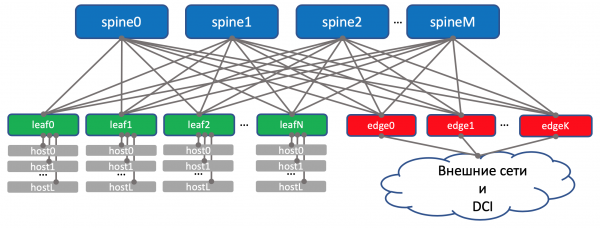
In the above diagram, I indeed placed edge and leaf on the same level. have accustomed us to consider the uplink (hence the term) as links going up. However, here the DCI 'uplink' goes back down, which somewhat disrupts our accustomed logic. In large networks, when data centers are further divided into smaller units — POD‘s (Point Of Delivery), separate Edge-POD‘s for DCI and external network access are allocated.
For ease of understanding in future discussions, I will still draw Edge above Spine, while we keep in mind that there is no intelligence on Spine and no difference when working with regular Leaf and Edge-leaf (although there may be nuances, but generally this is the case).
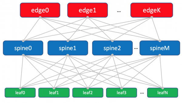
The factory diagram with Edge-leafs.
The trio of Leaf, Spine, and Edge forms the Underlay network or factory.
The task of the network factory (i.e., Underlay), as we have already determined in , is very simple — to ensure IP connectivity between machines both within a single DC and between them.
That is why the network is called a factory, just like the switching factory inside modular network boxes, which can be read about in .
In general, this topology is called a fabric because 'fabric' translates to 'tissue.' It's hard to disagree.
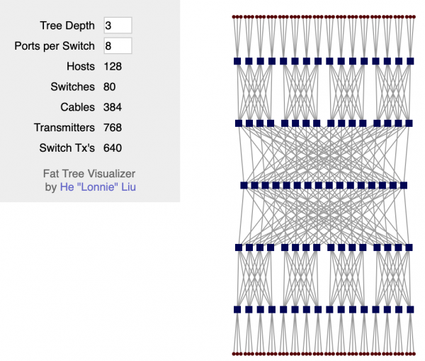
The fabric is entirely L3. No VLANs, no Broadcast—our wonderful programmers in LAN_DC can write applications that operate within the L3 paradigm, and virtual machines do not require Live Migration while retaining their IP address.
And once again: the answer to the question of why it's called a fabric and why L3 is in a separate document. .
DCI — Data Center Interconnect (Inter-DC)
DCI will be organized using Edge-Leaf, meaning they are our exit point to the backbone.
For simplicity, let's assume the data centers are connected by direct links.
Let's exclude external connectivity from consideration.
I recognize that every time I remove a component, I greatly simplify the network. Automation in our abstract network will work well, but in reality, it might lead to some workarounds.
That's true. Nevertheless, the goal of this series is to think and work on approaches, not to heroically solve imagined problems.
On the Edge-Leaves, the underlay is placed in a VPN and transmitted through the MPLS backbone (the very direct link).
This is what the high-level scheme looks like.

Routing
For routing within the data center, we will use BGP.
On the MPLS backbone, we use OSPF + LDP.
For DCI, meaning organizing connectivity in the underlay — BGP L3VPN over MPLS.
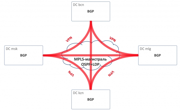
Overall routing scheme
There will be no OSPF or ISIS on the fabric (the routing protocol prohibited in the Russian Federation).
This means there will be no Auto-discovery or shortest path calculations — only manual (actually automatic, as we’re discussing automation here) configuration of the protocol, neighbor relationships, and policies.
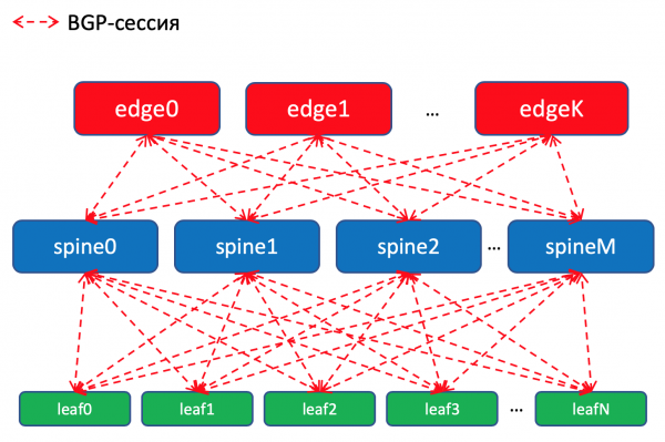
Routing scheme BGP within the data center
Why BGP?
There is a whole discussion on this topic by Facebook and Arista, which explains how to build very large data center networks using BGP. It's almost like reading a novel; I highly recommend it for a quiet evening.
There’s also a whole section in my article dedicated to this. Where I will also .
But if I sum it up briefly, no IGPs are suitable for networks of large data centers where the count of network devices reaches thousands.
Moreover, using BGP everywhere will prevent scattered support for multiple protocols and the synchronization between them.
Honestly, at our factory, which is unlikely to experience rapid growth, OSPF would have sufficed. These concerns are actually for megascalers and cloud titans. But let's imagine for a few editions that we need this and will use BGP, as Peter Lapukhov bequeathed.
Routing Policies
On Leaf switches, we import prefixes into BGP from Underlay interfaces with networks.
We will have a BGP session between each pair of Leaf-Spine connections, in which these Underlay prefixes will be announced throughout the network.
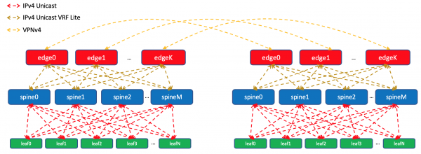
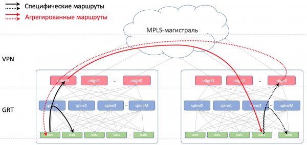
Within a single data center, we will distribute specifics imported on the ToR. On Edge-Leaves, we will aggregate these and announce them to remote data centers, descending down to the ToRs. This means each ToR will know precisely how to reach another ToR in the same data center and where the entry point is to access the ToR in a different data center.
In DCI, routes will be transmitted as VPNv4. For this, the Edge-Leaf interface towards the factory will be placed in a VRF, which we will call UNDERLAY, and adjacency with Spine on Edge-Leaf will be established within the VRF, while among the Edge-Leaves in VPNv4-family.
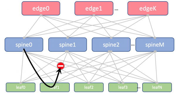
Additionally, we will prohibit re-announcing routes received from spines back to them.
We will not import Loopbacks on Leaf and Spine. We will only need them to determine the Router ID.
However, on Edge-Leaves, we will import it into Global BGP. Between the Loopback addresses, the Edge-Leaves will establish BGP sessions in IPv4 VPN-family with each other.
Between EDGE devices, we will have a stretched backbone on OSPF+LDP. Everything in one zone. A very simple configuration.
That's what the routing picture looks like.
BGP ASN
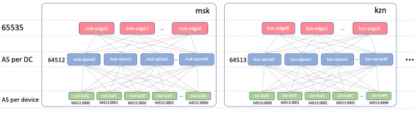
Edge-Leaf ASN
On Edge-Leaves, there will be one ASN across all data centers. This is important so that there is iBGP among Edge-Leaves and we don't fall into the nuances of eBGP. Let this be 65535. In reality, this could be a public AS number.
Spine ASN
On Spine, we will have one ASN per data center. We'll start here with the very first number from the range of private AS — 64512, 64513, and so on.
Why ASN in a data center?
Let's break this question down into two:
- Why have the same ASN on all spines of one data center?
- Why different ones in different data centers?
Why have the same ASN on all spines of one data center?
This is how the AS-Path of the Underlay route will look on Edge-Leaf:
[leafX_ASN, spine_ASN, edge_ASN]
When attempting to announce it back on the Spine, it will be discarded because its AS (Spine_AS) is already on the list.
However, within the data center, we are completely fine with the fact that the Underlay routes that have reached the Edge cannot descend downwards. All communication between hosts within the data center should occur at the spine level.
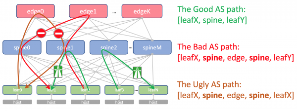
At the same time, aggregated routes from other data centers will still reach the ToRs without obstruction — their AS-Path will contain only ASN 65535 — the AS number of the Edge-Leafs, as they were created on them.
Why are they different in different data centers
Theoretically, we may need to connect Loopbacks of some service virtual machines between the data centers.
For example, we will run a Route Reflector on the host or (Virtual Network Gateway), which will establish a BGP session with the ToR and announce its loopback, which should be accessible from all data centers.
So this is how its AS-Path will look:
[VNF_ASN, leafX_DC1_ASN, spine_DC1_ASN, edge_ASN, spine_DC2_ASN, leafY_DC2_ASN]
And there should be no repeating ASNs anywhere here.
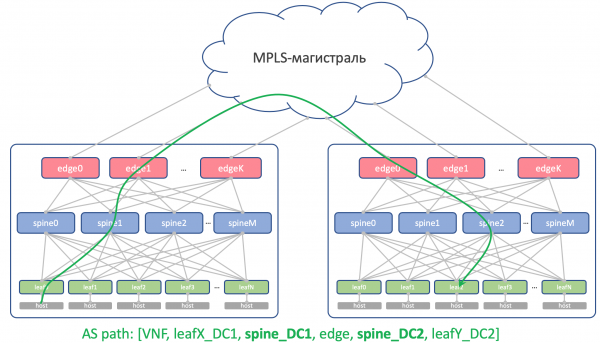
This means that Spine_DC1 and Spine_DC2 should be different, just like leafX_DC1 and leafY_DC2, which is exactly what we are approaching.
As you probably know, there are hacks that allow receiving routes with repeating ASNs despite the loop prevention mechanism (allowas-in on Cisco). And there are even legitimate uses for this. But it poses a potential vulnerability in network stability. I have personally fallen into it a couple of times.
And if we have the opportunity not to use dangerous things, we will take it.
Leaf ASN
We will have a unique ASN on each Leaf switch across the entire network.
We do this for the reasons outlined above: an AS-Path without loops, a BGP configuration without backdoors.
For routes between Leaf switches to pass unobstructed, the AS-Path must look like this:
[leafX_ASN, spine_ASN, leafY_ASN]
where leafX_ASN and leafY_ASN should ideally differ.
This is also required for the situation with announcing the VNF loopback between data centers:
[VNF_ASN, leafX_DC1_ASN, spine_DC1_ASN, edge_ASN, spine_DC2_ASN, leafY_DC2_ASN]
We will use a 4-byte ASN and generate it based on the ASN of the Spine and the number of the Leaf switch, namely, like this: Spine_ASN.0000X.
This is what the ASN picture looks like.
IP plan
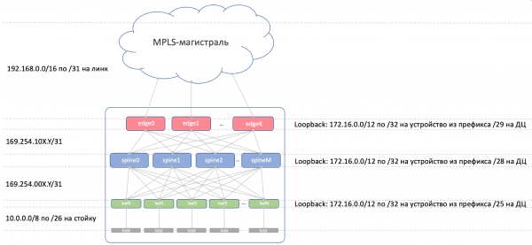
Principally, we need to allocate addresses for the following connections:
- The underlay network addresses between the ToR and the machine. They must be unique across the entire network so that any machine can connect with any other. A /26 per rack fits perfectly with a reserve. We will allocate /19 for data centers and /17 for the region. 10/8Link addresses between Leaf/Tor and Spine.
- Link addresses between Leaf/Tor and Spine.
They should be assigned algorithmically, calculated from the names of the devices that need to be connected.
Let it be… 169.254.0.0/16.
Specifically 169.254.00X.Y/31, where X — Spine number, Y — P2P network /31.
This will allow up to 128 racks and up to 10 Spines in the data center. Link addresses can (and will) be reused from data center to data center. - The Spine – Edge-Leaf connection will be organized on subnets 169.254.10X.Y/31, where similarly, X — Spine number, Y — P2P network /31.
- Link addresses from Edge-Leaf to the MPLS backbone. Here the situation is somewhat different — the connection point of all segments into one pie, so reusing the same addresses is not feasible — the next available subnet must be chosen. Therefore, we will base it on 192.168.0.0/16 and extract free ones from it.
- Loopback addresses. We will allocate the entire range for them. 172.16.0.0/12.
- Leaf — /25 per data center — the same 128 racks. We will allocate /23 for the region.
- Spine — /28 per data center — up to 16 Spines. We will allocate /26 for the region.
- Edge-Leaf — /29 per data center — up to 8 boxes. We will allocate /27 for the region.
If we do not have enough allocated ranges in the data center (and we won’t — we claim to be hyper-scaler), we simply allocate the next block.
Here's the picture with IP addressing.
Loopbacks:
The prefix
Device role
Region
Data Center
172.16.0.0/23
edge
172.16.0.0/27
en
172.16.0.0/29
msk
172.16.0.8/29
kzn
172.16.0.32/27
sp
172.16.0.32/29
bcn
172.16.0.40/29
mlg
172.16.0.64/27
cn
172.16.0.64/29
sha
172.16.0.72/29
sia
172.16.2.0/23
spine
172.16.2.0/26
en
172.16.2.0/28
msk
172.16.2.16/28
kzn
172.16.2.64/26
sp
172.16.2.64/28
bcn
172.16.2.80/28
mlg
172.16.2.128/26
cn
172.16.2.128/28
sha
172.16.2.144/28
sia
172.16.8.0/21
leaf
172.16.8.0/23
en
172.16.8.0/25
msk
172.16.8.128/25
kzn
172.16.10.0/23
sp
172.16.10.0/25
bcn
172.16.10.128/25
mlg
172.16.12.0/23
cn
172.16.12.0/25
sha
172.16.12.128/25
sia
Underlay:
The prefix
Region
Data Center
10.0.0.0/17
en
10.0.0.0/19
msk
10.0.32.0/19
kzn
10.0.128.0/17
sp
10.0.128.0/19
bcn
10.0.160.0/19
mlg
10.1.0.0/17
cn
10.1.0.0/19
sha
10.1.32.0/19
sia
Lab
Two vendors. One network. ADSM.
Juniper + Arista. Ubuntu. The good old Eva.
The number of resources on our virtual machine in Mirana is still limited, so for practice we will use this greatly simplified network.
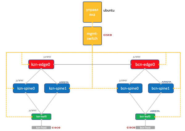
Two data centers: Kazan and Barcelona.
- Two spines in each: Juniper and Arista.
- One tor (Leaf) in each — Juniper and Arista, with one connected host (we will take a lightweight Cisco IOL for this).
- One Edge-Leaf node (currently only Juniper).
- One Cisco switch to rule them all.
- In addition to the network boxes, a management virtual machine is running. Under Ubuntu.
It has access to all devices; IPAM/DCIM systems, a bouquet of Python scripts, Ansible, and anything else that we may need will run on it.
of all network devices that we will try to reproduce with automation.
Conclusion
Is this the accepted practice? To make a short summary under each article?
So we chose Clos network within the data center, as we expect a lot of East-West traffic and want ECMP.
We divided the network into physical (underlay) and virtual (overlay). The overlay starts with the host — thus simplifying the requirements for the underlay.
We chose BGP as the routing protocol for underlay networks due to its scalability and flexibility of policies.
We will have separate nodes for organizing DCI — Edge-leaf.
The backbone will consist of OSPF+LDP.
DCI will be implemented based on MPLS L3VPN.
For P2P links, we will algorithmically calculate IP addresses based on device names.
Loopbacks will be assigned based on device roles and their location sequentially.
Underlay prefixes will only go to Leaf switches sequentially based on their location.
Assuming we do not have the equipment installed right now.
Therefore, our next steps will be to add them to the systems (IPAM, inventory), organize access, generate configuration, and deploy it.
In the next article, we will examine Netbox — the IP space inventory and management system in the data center.
Thanks
- Thanks to Andrey Glazkov aka @glazgoo for proofreading and edits
- Thanks to Alexander Klimenko aka @v00lk for proofreading and edits
- Thanks to Artyom Chernobai for KDPV
Source: habr.com
