

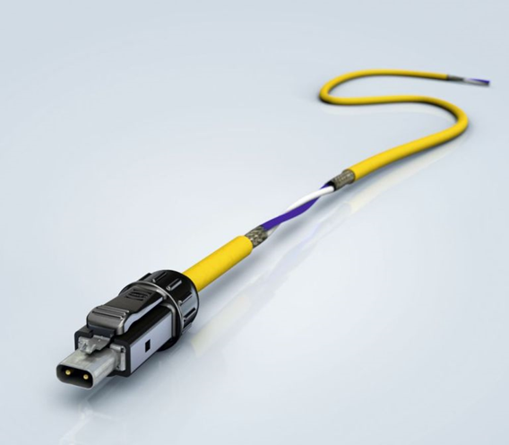
On February 5th of this year, a new standard for 10-megabit Ethernet was approved. Yes, you read that correctly: ten megabits per second.
What need is there for such a "small" speed in the 21st century? To replace the mess that hides under the bulky term "field bus" — Profibus, Modbus, CC-Link, CAN, FlexRay, HART, etc. There are too many of them, they are incompatible with each other and relatively complex to configure. What we want is simply to plug a cable into a switch and that's it. Just like with regular Ethernet.
And soon this will be possible! Meet: "802.3cg-2019 — IEEE Standard for Ethernet — Amendment 5: Physical Layer Specifications and Management Parameters for 10 Mb/s Operation and Associated Power Delivery over a Single Balanced Pair of Conductors."
What makes this new Ethernet interesting? First of all, it operates over a single twisted pair rather than four. Therefore, it has fewer connectors and thinner cables. And it can utilize the already installed twisted pair going to sensors and actuators.
You might argue that Ethernet works up to 100 meters, and the sensors are located much farther. Indeed, this was a problem in the past. But 802.3cg works over distances up to 1 km! On a single pair! Not bad, right?
In fact, it's even better: power can also be supplied over the same pair. Let's start with that.
IEEE 802.3bu Power over Data Lines (PoDL)
I think many of you have heard of PoE (Power over Ethernet) and know that two pairs of wires are needed to transmit power. The input/output of power is done at the midpoints of the transformers of each pair. It's impossible to do this using just one pair. Therefore, an alternative solution had to be implemented. How exactly is shown in the diagram below. For reference, classic PoE is also included.
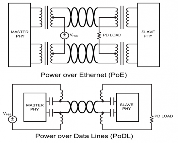
Here:
PSE – power sourcing equipment
PD – powered device
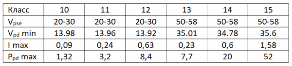
Initially, 802.3bu had 10 classes of power consumption:

The colors indicate three conditional gradations of source voltage: 12, 24, and 48V.
Designations:
Vpse — source voltage, V
Vpd min — minimum voltage at PD, V
I max — maximum current in the line, A
Ppd max — maximum power consumed by PD, W
With the introduction of protocol 802.3cg, six more classes were added:
Of course, with such diversity, PSE and PD must agree on the power class before applying full voltage. This is done using the SCCP (Serial Communications Classification Protocol). It is a low-speed protocol (333 bits/s) based on 1-Wire. It operates only when the main power is not applied to the line (including in sleep mode).
The block diagram shows how power is supplied:
- 10 mA of current is supplied and the presence of a 4V zener diode at the other end is checked
- the power class is negotiated
- main power is supplied
- if consumption drops below 10 mA – sleep mode is activated (with standby power supply of 3.3V)
- if consumption exceeds 1 mA – it exits sleep mode
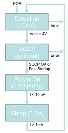
Negotiating the power class can be skipped if it is known in advance. This option is called Fast Startup Mode. It is used, for instance, in cars where there is no need to change the configuration of connected equipment.
Both PSE and PD can initiate the transition to sleep mode.
Now let's move on to the description of data transmission. It is also interesting: the standard defines two operating modes – long reach and short distance.
10BASE-T1L
This is the option for long distances. Its main characteristics are as follows:
- operating range – up to 1 km
- 18 AWG conductors (0.8 mm²)
- up to 10 intermediate connectors (and two end connectors)
- point-to-point operating mode
- full duplex
- symbol rate 7.5 Mbaud
- PAM-3 modulation, 4B3T encoding
- signal with an amplitude of 1V (1Vpp) or 2.4V
- support for Energy Efficient Ethernet (“quiet/refresh” EEE)
It is evident that this option is designed for industrial applications, access control systems, building automation, elevators. For managing chillers, air conditioners, fans located on rooftops. Or heating boilers and pumps found in technical rooms. In other words, a multitude of applications beyond industry. Not to mention the Internet of Things (IoT).
It is worth mentioning that 10BASE-T1 is just one of the standards for Single Pair Ethernet (SPE). There are also 100BASE-T1 (802.3bw) and 1000BASE-T1 (802.3bp). However, they were developed for automotive applications, which is why their range is only 15 meters (UTP) or 40 meters (STP). Nevertheless, plans are already underway for a long-range 100BASE-T1L. So, in the future, auto-negotiation of speed will be added.
Currently, in the absence of agreement, a 'quick start' interface is declared: less than 100ms from power up to the start of data exchange.
Another optional feature is increasing the transmission amplitude from 1V to 2.4V to improve the signal-to-noise ratio, reduce the number of errors, and combat industrial interference.
And, of course, EEE. This is a way to save electricity by turning off the transmitter if there is currently no data to send. The diagram shows how this looks:
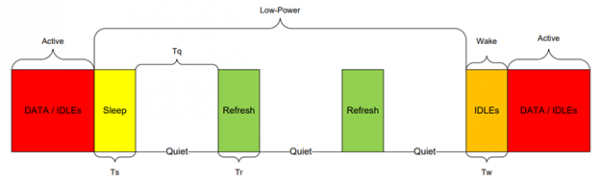
When there’s no data, we send a message 'I’m going to sleep' and disconnect. Occasionally, we wake up and send a message 'I’m still here'. When data appears, a warning 'I’m waking up' is sent to the opposite side, and transmission begins. Thus, only receivers are constantly running.
Now let's see what has been developed with the second version of the standard.
10BASE-T1S
From the last letter, it's clear that this protocol is for short distances (short reach). But why is it needed if T1L works at short distances? Let's read the specifications:
- operating range up to 15m in point-to-point mode
- duplex or half-duplex
- conductors 24-26AWG (0.2-0.13mm²)
- symbol rate 12.5Mbaud
- DME, encoding 4B5B
- signal with an amplitude of 1V (1Vpp)
- up to 4 intermediate connectors (and two terminal ones)
- no EEE support
Seems nothing special. So why is it needed? Here’s why:
- operating range up to 25m in multipoint mode (up to 8 nodes)
And this:
- operation mode with collision avoidance PLCA RS (PHY-Level Collision Avoidance Reconciliation Sublayer)
And this is much more interesting, isn’t it? As it helps to significantly reduce the number of wires in control cabinets, machines, robots, and cars. There are already proposals to use it as a replacement for I2C in servers, switches, and other electronics.
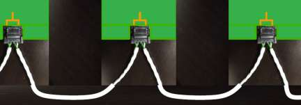
However, multipoint mode has its drawbacks. The main one is the shared communication medium. Of course, collisions are resolved using CSMA/CD. But it's unknown what the delay will be. And for some applications, this is critical. Therefore, the new standard supplemented multipoint with a special PLCA RS mode (see the next section).
The second drawback is that PoDL does not work in multipoint mode. So power supply will need to be provided via a separate cable or sourced locally.
However, in point-to-point mode, PoDL operates on T1S.
PLCA RS
This mode operates as follows:
- nodes exchange identifiers, the node with ID=0 becomes the coordinator
- the coordinator issues a BEACON signal to the network, indicating the start of a new transmission cycle and sends its data packet
- after transmitting the data packet, the transmission queue moves to the next node
- if within the time needed to transmit 20 bits the node has not started transmission, the queue passes to the next node
- when all nodes have transmitted data (or skipped their turn), the coordinator starts a new cycle
Overall, this resembles TDMA. However, the feature is that a node does not use its time frame if it has nothing to transmit. And the frame size is not rigidly set, as it depends on the size of the data packet being transmitted by the node. All this operates over standard Ethernet frames 802.3 (PLCA RS is not mandatory, so compatibility should exist).
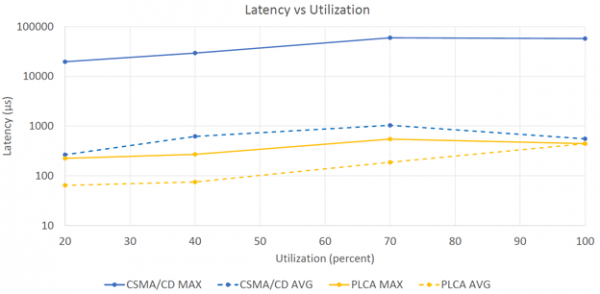
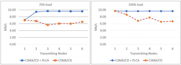
The result of using PLCA is shown below in the graphs. The first one shows the latency depending on the load, the second one shows the throughput based on the number of transmitting nodes. It is clearly visible that the latency has become much more predictable. In the worst case, it is two orders of magnitude lower than in the worst case of CSMA/CD:
And the channel throughput in the case of PLCA is higher since it does not waste resources on collision resolution:
Connectors
Initially, we selected from six connector options proposed by different companies. As a result, we settled on these two options:
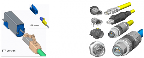
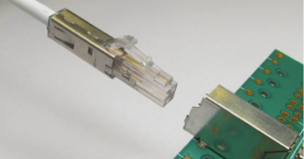
For normal operating conditions, the LC connector IEC 63171-1 from CommScope was chosen.
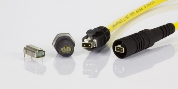
For harsh operating conditions – the family of connectors IEC 63171-6 (formerly 61076-3-125) from HARTING. These connectors are designed for protection ratings from IP20 to IP67.
Naturally, connectors and cables can be either UTP or STP.
Other
You can use a standard four-pair Ethernet cable, using each pair for a separate SPE channel. This avoids running four separate cables over long distances. Alternatively, you can use a single-pair cable and place a single-pair Ethernet switch at the far end.
Is it possible to connect this switch directly to the local network of the enterprise if the fiber optics are already extended far out? Plug in the sensors there, and monitor their readings here. Right over the network. Without interface converters or gateways.
And it doesn't necessarily have to be sensors. It could be cameras, intercoms, or smart bulbs. Actuators for some valves or turnstiles at entry points.
So interesting prospects are opening up. Of course, SPE is unlikely to replace all field buses. But it will definitely take a significant share. Especially in vehicles.
PS I could not find the text of the standard in the public domain. The information above was gathered piecemeal from various presentations and available materials on the internet. So there may be inaccuracies.
Source: habr.com
