


Introduction
An information system, from the user's perspective, is well-defined in GOST R V 51987 as an "automated system whose functioning results in the presentation of output information for subsequent use." If we consider the internal structure, any IS essentially constitutes a system of interconnected algorithms implemented in code. In a broader understanding, Turing's-Church thesis suggests that an algorithm (and consequently the IS) performs a transformation of a multitude of input data into a multitude of output data.
One could even say that the transformation of input data is the very purpose of the existence of an information system. Accordingly, the value of an IS and the entire complex of ISs is determined by the value of the input and output data.
Based on this, design should begin by focusing on the data, tailoring the architecture and methods to the structure and significance of the data.
Stored Data
A key stage in the preparation for design is obtaining the characteristics of all data sets planned for processing and storage. These characteristics include:
— Volume of data;
— Information about the data lifecycle (increase of new data, lifespan, handling of outdated data);
— Classification of data from the perspective of its impact on the company's core business (the triad of confidentiality, integrity, availability) along with financial metrics (e.g., the cost of data loss over the last hour);
— Geography of data processing (physical location of processing systems);
— Regulatory requirements for each class of data (e.g., Federal Law 152, PCI DSS).
Information Systems
Data is not only stored but also processed (transformed) by information systems. The next step after obtaining data characteristics is to conduct a comprehensive inventory of information systems, their architectural features, interdependencies, and infrastructure requirements in conditional units for four types of resources:
— Processor computing power;
— Volume of RAM;
— Requirements for the volume and performance of data storage systems;
— Requirements for data transmission networks (external channels, channels between IS components).
Requirements must be defined for each service/microservice within the information system.
It is essential to note the need for data on the impact of the information system on the company's core business in terms of the cost of downtime (in currency per hour).
Threat Model
A formal threat model must be available, detailing the threats against which data/services will be protected. This model includes not only confidentiality aspects but also integrity and availability. For example:
— Failure of the physical server;
— Failure of the top-of-the-rack switch;
— Disruption of the optical communication channel between data centers;
— Complete failure of the operational storage area network.
In some cases, threat models are developed not only for infrastructure components but also for specific information systems or their components, such as the failure of a database management system with logical data structure corruption.
All decisions made within the project to protect against unspecified threats are excessive.
Regulatory requirements
If the data being processed falls under special rules established by regulators, it is mandatory to have information about the data sets and processing/storage rules.
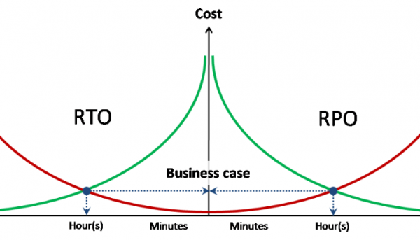
Target Indicators RPO / RTO
Designing any type of protection requires the establishment of target data loss indicators and target service recovery time for each described threat.
Ideally, the RPO and RTO should have associated costs for data loss and downtime per unit of time.
Segregation into Resource Pools
After gathering all the preliminary input information, the first step is to group data sets and information systems into pools based on threat models and regulatory requirements. The type of segregation for different pools is determined – either programmatic at the system software level or physical.
Examples:
— The contour processing personal data is completely physically separated from other systems;
— Backup copies are stored on a separate storage area network.
At the same time, pools can have partial independence; for example, two computing resource pools (processing power + RAM) can use a single storage data pool and a single data transmission resource pool.
Processing Power
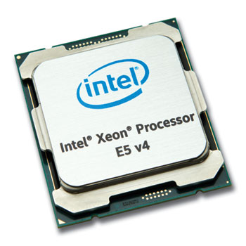
The abstract needs for processor power in a virtualized data center are measured by the number of virtual CPUs (vCPU) and their consolidation ratio on physical processors (pCPU). In this specific case, 1 pCPU equals 1 physical core of the processor (without considering Hyper-Threading). The number of vCPUs is summed across all defined resource pools (each of which may have its own consolidation ratio).
The consolidation ratio for loaded systems is obtained empirically, based on the existing infrastructure or during pilot installations and load testing. For unloaded systems, 'best practices' are applied. In particular, VMware cites an average ratio of 8:1.
Memory
The total memory requirement is obtained by simple summation. Overcommitment of memory is not recommended.
Storage Resources
Storage resource requirements are obtained by summing all pools based on capacity and performance.
Performance requirements are expressed in IOPS in conjunction with the average read/write ratio and, if necessary, maximum response latency.
Requirements for quality of service (QoS) should be specified separately for specific pools or systems.
Data Transmission Network Resources
Data transmission network requirements are obtained by simply summing all bandwidth pools.
Requirements for quality of service (QoS) and latencies (RTT) should be specified separately for specific pools or systems.
Within the requirements for data transmission network resources, requirements for isolation and/or encryption of network traffic and preferred mechanisms (802.1q, IPSec, etc.) are also indicated.
Architecture Selection
This guide does not consider any choice other than x86 architecture and 100% server virtualization. Therefore, the choice of the computing subsystem architecture is reduced to selecting the server virtualization platform, server form factor, and overall server configuration requirements.
A key point in the selection is clarity on using the classic approach with separation of data processing, storage, and transmission functions or a converged one.
Classic Architecture implies the use of intelligent external storage and data transmission subsystems, while servers contribute only processing power and RAM to the overall pool of physical resources. In extreme cases, servers become completely anonymous, lacking not only their own disks but even a system identifier. In this case, the operating system or hypervisor is booted from embedded flash drives or from an external storage system (boot from SAN).
Within the classical architecture, the choice between blades and racks is primarily based on the following principles:
— Economic efficiency (on average, rack servers are cheaper);
— Computational density (blades have higher density);
— Power consumption and heat generation (blades have higher values per unit);
— Scalability and manageability (blades generally require less effort for large installations);
— Use of expansion cards (the choice for blades is very limited).
Converged architecture (also known as hyper-converged) combines processing and storage functions, leading to the use of local disks in servers and consequently abandoning the form factor of traditional blades. Converged systems use either rack servers or clustered systems that combine multiple blade servers and local disks within a single chassis.
CPU / Memory
To correctly calculate the configuration, one must understand the type of load for the environment or each of the independent clusters.
CPU bound – an environment constrained by processing power. Adding RAM will not change performance (the number of VMs on the server).
Memory bound – an environment constrained by RAM. More RAM on the server allows for a greater number of VMs to be run on the server.
GB / MHz (GB / pCPU) – the average ratio of RAM and processing power consumption for a particular load. This can be used to calculate the necessary amount of memory for a given performance and vice versa.
Server configuration calculation
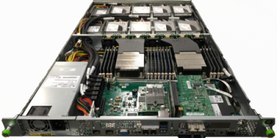
First, it is necessary to identify all types of loads and decide whether to combine or separate different computing pools across various clusters.
Next, for each of the identified clusters, the ratio of GB / MHz is determined based on the known load in advance. If the load is not known in advance but there is a rough understanding of the level of CPU utilization, standard vCPU:pCPU ratios can be used to translate pool requirements into physical resources.
For each cluster, the total vCPU requirements of the pools are divided by the ratio:
vCPU sum / vCPU:pCPU = pCPU sum – required number of physical cores
pCPU sum / 1.25 = pCPU ht – number of cores adjusted for Hyper-Threading
Assume we need to calculate a cluster with 190 cores / 3.5 TB of RAM. In this case, we assume a target CPU utilization of 50% and 75% for RAM.
pCPU
190
CPU util
50%
Mem
3500
Mem util
75%
Socket
Core
Srv / CPU
Srv Mem
Srv / Mem
2
6
25,3
128
36,5
2
8
19,0
192
24,3
2
10
15,2
256
18,2
2
14
10,9
384
12,2
2
18
8,4
512
9,1
In this case, we always use rounding up to the nearest whole number (=ROUNDUP(A1;0)).
From the table, it becomes clear that several server configurations meet the target metrics:
— 26 servers 2*6c / 192 GB
— 19 servers 2*10c / 256 GB
— 10 servers 2*18c / 512 GB
The choice among these configurations must be made based on additional factors, such as thermal capacity and available cooling, existing servers, or cost.
Considerations for choosing a server configuration
Wide VMs. When placing wide VMs (comparable to 1 NUMA node and larger), it is recommended to choose a server configuration that allows such VMs to stay within a NUMA node if possible. With a large number of wide VMs, there is a risk of fragmenting cluster resources, and in this case, servers should be chosen that allow for the densest placement of wide VMs.
Single point of failure domain size.
The choice of server size is also based on the principle of minimizing the single point of failure domain. For example, when choosing between:
— 3 x 4*10c / 512 GB
— 6 x 2*10c / 256 GB
With all else being equal, the second option should be chosen, since if one server fails (or is under maintenance), not 33% of cluster resources are lost, but 17%. Similarly, the number of VMs and IS affected by the failure is halved.
Calculating the performance of a classic storage system
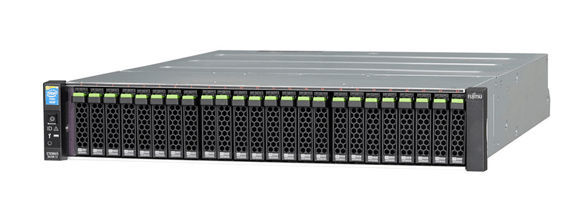
The classic storage system is always calculated based on the worst-case scenario, excluding the influence of operational cache and optimization of operations.
We will consider the mechanical performance from the disk (IOPSdisk) as the basic performance indicators:
— 7.2k – 75 IOPS
— 10k – 125 IOPS
— 15k – 175 IOPS
Next, the number of disks in the disk pool is calculated using the following formula: = TotalIOPS * ( RW + (1 –RW) * RAIDPen) / IOPSdisk. Where:
— TotalIOPS – total required performance in IOPS from the disk pool
— RW – percentage of read operations
— RAIDpen – RAID penalty for the selected RAID level
More about RAID devices and RAID Penalty is discussed here — and and
Based on the number of disks obtained, possible options are calculated that meet the storage capacity requirements, including those with tiered storage.
The calculation of systems using SSD as a storage tier is considered separately.
Features of calculating systems with Flash Cache
Flash Cache – a general term for all proprietary technologies that use flash memory as a second-level cache. When using flash cache, the storage system is usually calculated to meet the established load from magnetic disks, while peak loads are handled by the cache.
It is important to understand the load profile and the degree of localization of accesses to the storage volume blocks. Flash cache is a technology for workloads with high request localization and is practically not applicable for evenly loaded volumes (as in analytical systems).
Calculation of hybrid systems low-end / mid-range
Hybrid systems of the lower and mid-range classes use tiered storage with data movement between levels on a schedule. The block size of tiered storage in the best models is 256 MB. These characteristics do not allow the tiered storage technology to be considered a performance-enhancing technology, as is mistakenly believed by many. Tiered storage in lower and mid-range systems is a cost optimization technology for systems with pronounced uneven load.
For multi-tier storage, performance is primarily calculated at the upper level, while the lower storage layer is considered only to provide the missing storage capacity. For a hybrid multi-tier system, it is essential to use flash cache technology within the multi-tier pool to compensate for performance drops for suddenly heated data from the lower level.
Using SSDs in a multi-tier disk pool
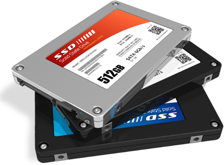
Using SSDs in a multi-tier disk pool varies depending on the specific implementation of flash cache algorithms by each manufacturer.
The general practice for storage policy in an SSD-level disk pool is SSD first.
Read Only Flash Cache. For read-only flash cache, the SSD storage level appears when write operations are significantly localized, regardless of the cache.
Read / Write Flash Cache. In the case of write flash cache, the maximum cache size is first established, and the SSD storage level appears only when the cache size is insufficient to handle the entire localized load.
The performance of SSDs and cache is calculated each time based on manufacturer recommendations, but always for the worst-case scenario.
Source: habr.com
