

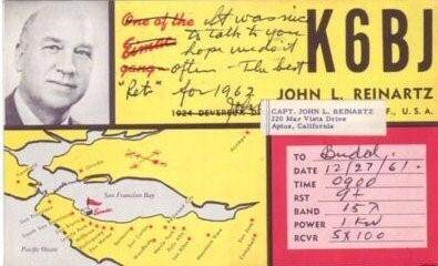
On November 27, 1923, American radio amateurs John Reinartz (1QP) and Fred Schnell (1MO) conducted a two-way transatlantic radio communication with French amateur radio operator Léon Deloy (F8AB) at a wavelength of about 100 meters. This event had a huge impact on the development of the global amateur radio movement and shortwave communication. One of the key factors contributing to its success was Schnell and Reinartz's improvement of Armstrong's regenerative receiver design. The enhancements were so effective that the names "Schnell" and "Reinartz" became synonymous with such receivers.
It was an ordinary "reinartz"...
The all-knowing Wikipedia about John Reinartz could not provide me with any information. This historical account was written based on various publications by American radio amateurs, as well as materials from the January 1924 issue of "QST" magazine and the 23-24 issue of the "Radio Amateur" magazine from 1926.
John Reinartz was born on March 6, 1894, in Germany. In 1904, the Reinartz family moved from Germany to South Manchester, Connecticut, USA. John became interested in radio in 1908 and, in 1915, was one of the first in the country to join the national association of amateur radio operators in the USA (ARRL).
The era of exploring radio waves was starting. Leading laboratories in the world and simple enthusiasts were searching for technical solutions for radio receiving and transmitting devices. As I mentioned in previous articles in the series, electromechanical generators and crystal detectors were being actively replaced by solutions using vacuum tubes.
One of the breakthroughs of that time was the invention of regenerative radio receiver. The solution was simple, inexpensive, and allowed for the creation of a device for long-distance radio reception using just one vacuum tube. The challenge lay in mechanically adjusting the position of the feedback coil. The higher the reception frequency, the more "critical" this adjustment became.
John Reinartz significantly improved Armstrong's design by firmly securing the feedback coil. The adjustment of the feedback amount in Reinartz's receiver (Reinartz Tuner) was performed using a variable capacitive capacitor (VVC). To reduce the "sharpness" of the VVC's settings, vernier devices were used.
Unlike Armstrong, who spent his entire life litigating his patents and priorities, Reynarz simply published his design in the June 1921 issue of 'QST'. This was followed by two more articles with improvements.
In there is an example of a one-tube receiver implementation by Reynarz:
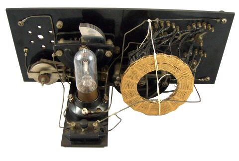
… and it worked very simply…
Valve circuit design impresses with the raw beauty of technical solutions. Everything is in its place, nothing superfluous.
In this essay, I specifically decided not to include schematics from publications of the 1920s, and referred to the classic first edition of 'Young Radio Amateur' by Borisov. Here's how simply and clearly he illustrated the operation of a direct amplification receiver using one tube:
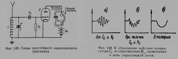
We discussed the operation of the resonant circuit at the input of the circuit and the headset with a blocking capacitor at the output in the article about Losev's 'crystadine'. Let's analyze the operation of the RcCc circuit at the input of the triode amplifier.
The RcCc circuit is called a 'grid leak' (from the English: grid leak), it is used for 'grid detection', where the tube amplifier both detects the signal and amplifies it.
Graph (a) shows the anode current of the amplifier when the 'grid leak' is absent. We see that the input signal is amplified directly.
After introducing the 'grid leak' into the controlling grid circuit, we observe ripple currents in the anode circuits (graph b). The blocking capacitor filters out the high-frequency components (graph c), and we receive audio frequency signals in the headsets.
Now let's see what Armstrong and Reynarz did with this circuit:
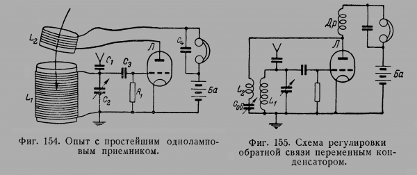
Armstrong introduced a feedback coil into the anode circuits of the amplifier. With positive feedback, the signal in the resonant circuit coil is augmented by a signal from the feedback coil. The level of feedback is chosen so that the amplifier is on the verge of self-oscillation, providing the maximum level of amplification of the input signal.
When receiving on short waves, tuning Armstrong's circuit to operate in regenerative mode was problematic: the slightest movement of the feedback coil led to significant changes in reception parameters.
John Reynard solved the problem by fixing the mutual positions of coils L1 and L2 so that the mutual inductances between them and the changes in the capacitance of the feedback capacitor were sufficient for the receiver to operate in regeneration mode over a wide range of wavelengths.
To improve the stability of operation, a choke Dr was introduced into the anode circuits of the lamp. It provided isolation of the high-frequency receiver circuits from the low-frequency ones and effectively filtered out the radio frequency component from the audio frequency signal.
For 'stretching' the frequency and feedback settings, verniers were used — reducing gears between the tuning knobs and the capacitor shafts. These technical solutions ensured smooth tuning of the receiving frequency and, most importantly, the feedback level.
When tuning the receiver to a radio station, the feedback level was initially increased according to the rising volume of the noise from the ether. Essentially, the receiver entered 'autodyne' mode, meaning it began to operate as a heterodyne receiver. When tuned to the station frequency, a whistle from the beats of its own oscillations and the carrier frequency would first occur. This way, operations with a radiotelegraph (CW) were conducted.
When receiving broadcasting radio stations (AM), the frequency adjustment continued until 'zero beats' were achieved, and then the feedback amount was reduced based on sound quality.
Interestingly, an effect was noted: the regenerative receiver, when inaccurately tuned to the station, often began to adjust the frequency and phase of its own oscillations according to the carrier signal. This auto-tuning ensured synchronous receiving mode.
… although not perfectly
Regenerative receivers have both advantages and disadvantages.
Among the advantages, one should note the high 'price-quality' ratio. Additionally, 'regenerators' offered a certain versatility in use: they received broadcasting stations in regeneration mode; in autogeneration mode, they operated as heterodyne receivers, and they could receive radiotelegraph signals.
The main disadvantage was the need for constant adjustment of the feedback and parasitic radiation of the receiver into the ether. Remember Vasyak Taburetkin!
After the war, regenerative receivers began to be replaced by superheterodyne receivers. But that's another story...
From the author.
In the 1920s, John Reyner studied the propagation of short waves. He participated in an Arctic expedition.
He worked at RCA starting in 1933.
In 1938, he joined the navy and completed his service in 1946 as a captain.
In 1946, he returned to work at RCA.
From 1949, he worked at Eimac.
On February 1, 1960, a grand banquet was held in honor of Reyner's retirement, attended by over two hundred prominent radio enthusiasts.
He passed away on September 18, 1964.
References used
1. 'QST', 1924, No. 1
2. 'Radio Amateur', 1926, No. 23-24
3. Borisov V.G. The Young Radio Amateur – Moscow: Gosenergoizdat, 1951
Other publications in the series
1.
2.
3.
4.
Source: habr.com
