

We have developed a data center network design that allows for the deployment of compute clusters larger than 100,000 servers with a peak bisection bandwidth of over one petabyte per second.
In Dmitry Afanasyev's presentation, you will learn about the fundamental principles of the new design, the scaling of topologies, the challenges that arise, possible solutions, the intricacies of routing and scaling of forwarding plane functions in modern network devices within densely connected topologies with a large number of ECMP routes. Additionally, Dima provided a brief overview of external connectivity, the physical layer, the cabling system, and ways to further increase capacity.
— Good afternoon, everyone! My name is Dmitry Afanasyev, I am a network architect at Yandex, and I primarily focus on data center network design.
My talk will be about the updated Yandex data center network. This is largely an evolution of the design we had, but at the same time, there are some new elements. This is an overview presentation, as we needed to fit a lot of information into a short time. We will start with the choice of logical topology. Then there will be an overview of the control plane and the scalability issues of the data plane, the choice of what will happen at the physical level, and we will look at some device features. We will briefly touch on what's happening in the data center with MPLS, which we discussed some time ago.
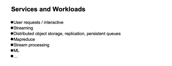
So, what is Yandex in terms of loads and services? Yandex is a typical hyperscaler. From the users' perspective, we primarily process user requests. We also have various streaming services and data delivery, as we also offer storage services. Closer to the backend, there are infrastructure loads and services, such as distributed object storage, data replication, and, of course, persistent queues. One of the main types of loads is MapReduce and similar systems, stream processing, machine learning, etc.
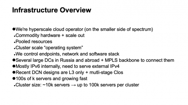
How is the infrastructure structured upon which all this operates? Again, we are quite a typical hyperscaler, though perhaps we lean a bit closer to the side of the spectrum occupied by smaller hyperscalers. But we have all the attributes. We utilize commodity hardware and horizontal scaling wherever possible. We have full resource pooling: we do not work with individual machines or racks but combine them into a large pool of interchangeable resources with some additional services that handle scheduling and allocation, and we work with this entire pool.
This leads us to the next level — the operating system for the computing cluster. It is very important that we fully control the technology stack that we use. We control the endpoints (hosts), the network, and the software stack.
We have several large data centers in Russia and abroad. They are connected by a backbone utilizing MPLS technology. Our internal infrastructure is almost entirely built on IPv6, but since we need to service external traffic, which is still mainly coming in via IPv4, we must find ways to route requests arriving over IPv4 to the frontend,serversand we also need to connect a bit to the external IPv4 internet — for example, for indexing.
The last few iterations of the data center network design use multi-level Clos topologies, and only L3 is applied in them. We moved away from L2 some time ago and breathed a sigh of relief. Finally, our infrastructure includes hundreds of thousands of computational (server) instances. The maximum size of a cluster some time ago was around 10,000 servers. This is largely due to how the very operating systems of the cluster level, schedulers, resource allocation, etc., can function. As there has been progress on the infrastructure software side, the target size is now around 100,000 servers in a single computing cluster, and we face the challenge of building network fabrics that allow efficient resource pooling in such a cluster.
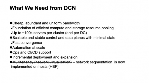
What do we want from a data center network? First and foremost, we need a lot of inexpensive and adequately uniformly distributed bandwidth. This is because the network is the foundation that allows us to pool resources. The new target size is around 100,000 servers in a single cluster.
We also want a scalable and stable control plane, as this large infrastructure can bring a lot of headaches even from random events, and we don’t want the control plane to add to our troubles. At the same time, we want to minimize the state within it. The less state there is, the better and more stable everything works, and the easier it is to diagnose.
Of course, we need automation because managing such infrastructure manually is impossible, and has been for some time. We need operational support and CI/CD integration to the extent it can be provided.
With such large data centers and clusters, the challenge of supporting incremental deployments and scaling without service interruption has become quite urgent. For clusters with a size of about a thousand machines or close to ten thousand, they could still be rolled out as a single operation — that is, when planning infrastructure expansion, several thousand machines are added in one go. However, a cluster with nearly 100,000 machines does not appear all at once; it is built over a period of time. Ideally, throughout this entire period, what has already been deployed, the infrastructure that has been set up, should remain accessible.
One requirement that we had and then eliminated was support for multitenancy, meaning virtualization or network segmentation. Now we don’t need to do this at the network fabric level because segmentation has shifted to the hosts, making scaling much easier. Thanks to IPv6 and the large address space, we no longer had to use duplicate addresses within our infrastructure; all addressing was unique. By moving network filtering and segmentation to the hosts, we no longer need to create virtual network entities within data center networks.
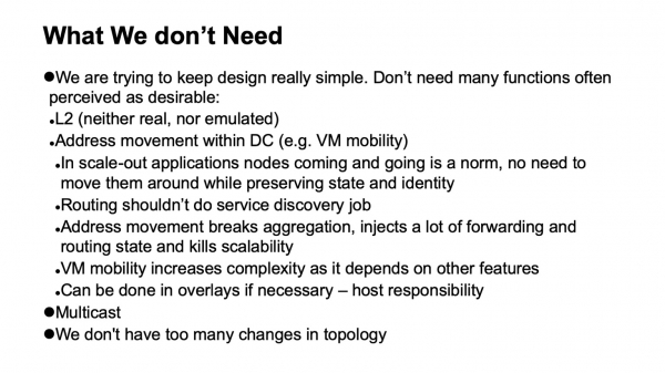
A very important thing is what we don't need. If there are any functions that can be removed from the network, it greatly simplifies life, and generally expands the choice of available hardware and software, making diagnostics much easier.
So, what do we not need, what have we been able to give up, not always gladly at the moment it was happening, but with great relief when the process was completed?
First and foremost, the abandonment of L2. We don't need L2, neither real nor emulated. It is not used to a significant extent because we control the application stack. Our applications scale horizontally, they operate with L3 addressing, and they are not particularly concerned if a single instance goes down; they simply roll out a new one, which doesn't need to come up on the old address because there is a separate level for service discovery and monitoring of machines in the cluster. We do not shift that task to the network. The network's job is to deliver packets from point A to point B.
We also do not have situations where addresses move within the network, and this needs to be tracked. In many designs, this is generally necessary to support VM mobility. We do not use virtual machine mobility in the internal infrastructure of Yandex, and furthermore, we believe that, even if this is done, it should not be supported by the network. If it is really necessary to implement, it should be done at the host level, and addresses that may migrate should be placed in overlays, so as not to disturb and introduce too many dynamic changes into the routing system of the underlay (transport network).
Another technology we do not use is multicast. I can explain in detail why to those interested. It greatly simplifies life because if anyone has dealt with it and looked at what the control plane of multicast looks like—in all installations, except the very simplest, it's a major headache. Moreover, it is difficult to find a well-functioning open implementation, for example.
And finally, we design our networks in such a way that there are not too many changes happening in them. We can rely on the fact that the flow of external events in the routing system is small.
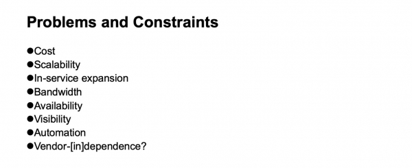
What issues and limitations must we consider when developing a data center network? Cost, of course. Scalability — to what extent do we want to grow? The necessity of expansion without service interruption. Bandwidth and availability. The visibility of what is happening in the network for monitoring systems and operations teams. Support for automation — again, as much as possible, since different tasks may be solved at different levels, including by introducing additional layers. And non-vendor dependency — although in different historical periods, depending on which slice we examine, this independence has been easier or harder to achieve. If we take a slice of network device chips, until recently, discussing independence from vendors, especially if we wanted high-throughput chips, could only be done conditionally.
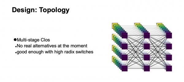
What logical topology will we use to build our network? It will be a multilayer Clos. In fact, there are currently no real alternatives. The Clos topology is quite good, even when compared to various advanced topologies that are more a matter of academic interest, especially if we have switches with a large radix.
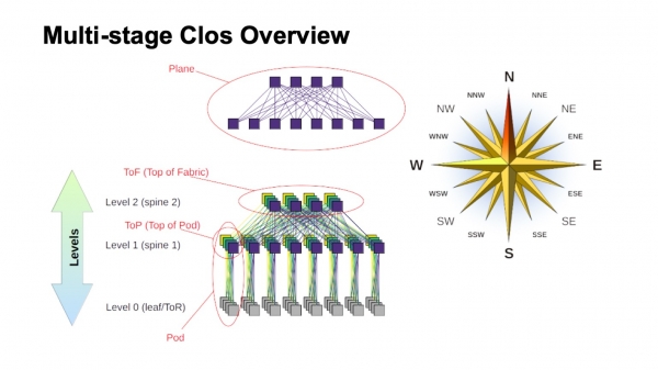
How is a multilayer Clos network generally structured, and what are the various components called within it? First of all, a wind rose, to orient where north, south, east, and west are. Such networks are usually built by those who have a very high traffic volume from west to east. Regarding the other components, at the top is a virtual switch made up of smaller switches. This is the core idea of recursive Clos network construction. We take elements with a certain radix and connect them in such a way that what results can be viewed as a switch with a larger radix. If even more is needed, the procedure can be repeated.
In cases like two-tier Clos networks, where components can be clearly defined as vertical in my diagram, they are commonly referred to as planes. If we were to build a Clos network with three tiers of spine switches (all switches that are neither boundary nor ToR switches and are used solely for transit), the planes would appear more complex; the two-tier version looks like this. The block of ToR or leaf switches along with the associated first-level spine switches is called a Pod. The spine switches at the top of the Pod are referred to as the top of the Pod. The switches that sit at the top of the entire fabric comprise the upper layer of the fabric, known as the Top of fabric.
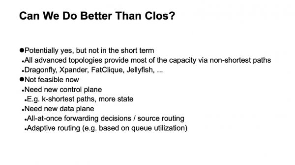
Of course, a question arises: Clos networks have been built for some time, and the idea dates back to the days of classical telephony, TDM networks. Is there something better available, or can it be done in a better way? The answer is both yes and no. Theoretically, yes, but in practice, not in the near future. There are several interesting topologies, some of which are already in production; for example, Dragonfly is used in HPC applications. There are also intriguing topologies like Xpander, FatClique, and Jellyfish. If you look at papers presented at conferences like SIGCOMM or NSDI recently, you will find a considerable number of works on alternative topologies that have better properties (in one way or another) than Clos.
However, all these topologies share one interesting property that hinders their adoption in data center networks that we aim to build on commodity hardware and which are reasonably priced. In all these alternative topologies, much of the bandwidth is unfortunately not available via the shortest paths. Therefore, we immediately lose the ability to use the traditional control plane.
Theoretically, the solution to this problem is known. For example, variations of link state using k-shortest path exist but, again, there are no protocols that have been implemented in production and are widely available on hardware.
Moreover, since most of the capacity is available not through the shortest paths, we need to modify not only the control plane so it can select all these paths (and, by the way, this is significantly more complex in the control plane). We also need to modify the forwarding plane, and typically at least two additional features are required. This is the ability to make all decisions about packet forwarding at once, for example, on the host. In fact, this is source routing; it’s sometimes referred to in literature on interconnection networks as all-at-once forwarding decisions. Additionally, adaptive routing is a feature we need in network elements, which involves selecting the next hop based on the information about the lowest queue load. For example, there may be other options.
Thus, the direction is interesting, but unfortunately, we cannot apply it right now.
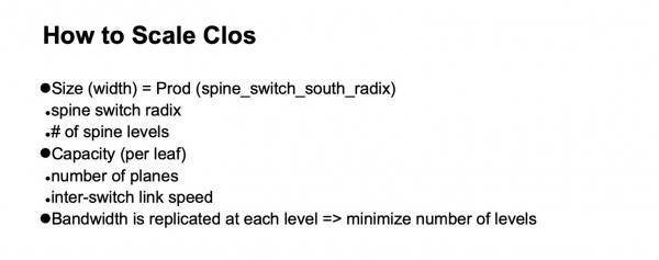
Okay, we stopped at the logical Clos topology. How are we going to scale it? Let’s take a look at how it is structured and what can be done.
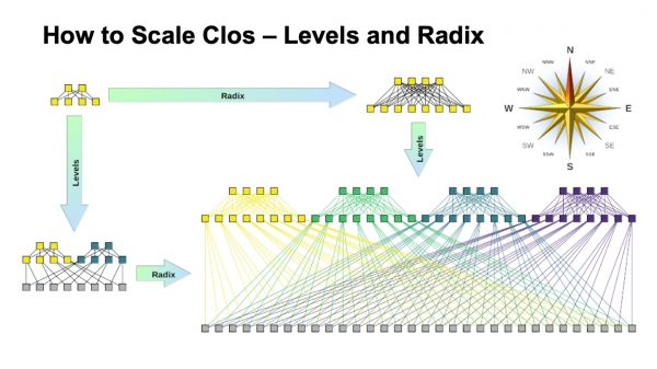
In a Clos network, there are two main parameters that we can vary to achieve different results: the radix of the elements and the number of levels in the network. I have a schematic representation of how both affect the size. Ideally, we combine both.
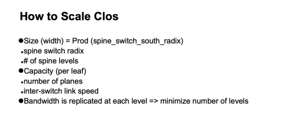
It is evident that the final width of the Clos network is the product across all levels of the spine switches of the southern radix, which indicates how many links we have downward and how it branches. This is how we scale the size of the network.
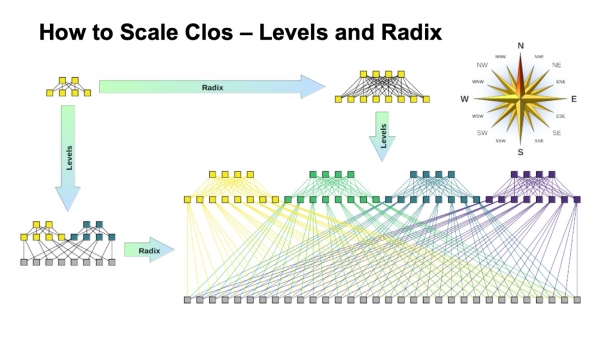
Regarding capacity, especially on ToR switches, there are two scaling options. We can either retain the overall topology while using faster links, or we can add more planes.
If we look at the unfolded version of the Clos network (in the bottom right corner) and return to this image with the Clos network at the bottom…
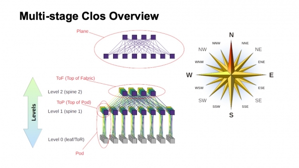
… then this is exactly the same topology, but in this slide, it’s more compactly collapsed, and the factory planes are overlaid. It’s the same thing.
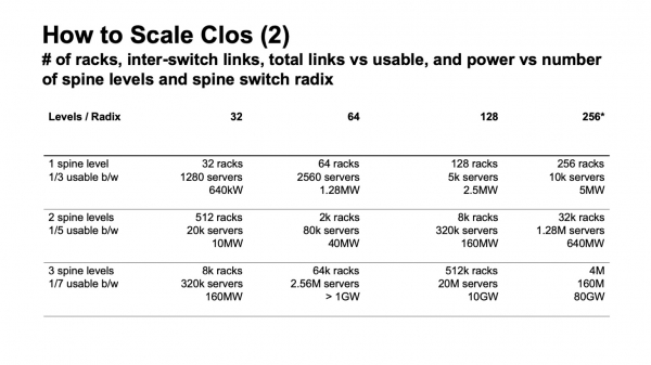
What does scaling a Clos network look like in numbers? Here I present data on the maximum width that can be achieved, the maximum number of racks, ToR switches, or leaf switches, if they are not in racks, we can obtain depending on the radix of the switches used for the spine levels and how many levels we use.
Here it shows how many racks we can have, how many servers, and approximately how much power this might consume, based on 20 kW per rack. Earlier, I mentioned that we are aiming for a cluster size of around 100,000 servers.
It is clear that within this setup, there are two and a half interesting options. There is an option with two layers of spine switches and 64-port switches, which falls a bit short. Then, there are suitable options for 128-port spine switches with two levels, or switches with a radix of 32 with three levels. In all cases, where there is a higher radix and more levels, a very large network can be built, but if you look at the expected consumption, it is generally in gigawatts. We can lay the cables, but it is unlikely that we will receive that much electricity at one site. Looking at the statistics, public data on data centers shows that very few can be found with a calculated capacity over 150 MW. What exceeds that is usually data center campuses, several large data centers located quite close to each other.
There is also an important parameter. If you look at the left column, it indicates usable bandwidth. It's easy to notice that in a Clos network, a noticeable portion of the ports is used to connect switches to each other. Usable bandwidth is what can be allocated outward, toward the servers. Naturally, I'm talking about conditional ports and specifically about the bandwidth. Generally, the links within the network are faster than the links toward the servers, but for each unit of bandwidth that we can push out to our server equipment, there is also some bandwidth used internally within the network. The more levels we have, the greater the specific overhead to provide that bandwidth outward.
Moreover, even this additional bandwidth is not exactly uniform. As long as the spans are short, we can use something like DAC (direct attach copper, i.e., twinax cables), or multimode optics, which are still somewhat reasonably priced. As soon as we move to longer spans — this is usually single mode optics, and the cost of that additional bandwidth increases significantly.
And again, returning to the previous slide, if we build a Clos network without over-subscription, it’s not hard to look at the diagram and see how the network is constructed—adding each level of spine switches, we replicate the entire bandwidth that was at the bottom. Plus, with each level comes the same amount of bandwidth, as much as was on the previous level, ports on switches, and as many transceivers. Therefore, it's very desirable to minimize the number of levels of spine switches.
From this picture, it’s clear that we really want to build on something like switches with a radix of 128.
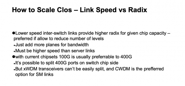
Basically, everything I've just described is also applicable here; this slide is more for later consideration.
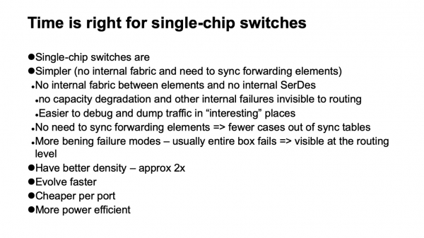
What options do we have for choosing such switches? A very pleasant piece of news for us is that networks can finally be built on single-chip switches. This is great news; they have many nice features. For example, they have almost no internal structure. This means they are easier to break. They do break, of course, but fortunately, they break entirely. Modular devices often have a lot of faults (very unpleasant ones), where from the neighbors' and control plane's perspective, everything seems to be functioning, but, for example, a part of the fabric has failed, and it’s not operating at full capacity. Traffic is balanced based on the assumption that it is fully functional, which can lead to overload.
Or, for example, problems arise with the backplane because inside the modular device, there are also high-speed SerDes—it’s really complex inside. Or the tables between forwarding elements may or may not synchronize. In general, any high-performance modular device, which consists of a large number of elements, typically contains the same Clos network inside, but it’s very hard to diagnose. Often, even the vendor finds it difficult to diagnose.
It has a wide range of failure scenarios where the device degrades but does not completely drop out of the topology. Given that we have a large network with active load-balancing among identical elements and a highly regular structure—meaning one path that works well is indistinguishable from another—it is more advantageous for us to simply lose some devices from the topology rather than ending up in a situation where some of them appear to work but are unreliable.
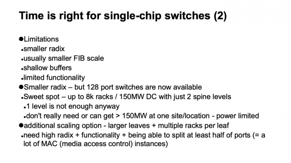
Another nice feature of single-chip devices is that they evolve better and faster. They also typically have better capacity. If we consider the large assembled systems we have overall, the capacity per rack unit for ports of the same speed is almost twice as good as that of modular devices. Devices built around a single chip end up being noticeably cheaper than modular ones and consume less power.
However, of course, this comes with its drawbacks. First, there is almost always a smaller radix than with modular devices. While we can obtain a single-chip device with 128 ports, modular ones can now easily accommodate several hundred ports without major issues.
This results in significantly smaller forwarding tables and, generally, everything concerning the scalability of the data plane. Shallow buffers. And usually, functionality is rather limited. However, it turns out that if one is aware of these limitations and takes timely measures to work around or simply account for them, it isn't so daunting. The smaller radix in the newly emerged devices with a radix of 128 is no longer a problem; we can arrange in two layers of spines. Nothing interesting can be built with a size smaller than two layers anyway, as with just one level, you end up with very small clusters. Even our previous designs and requirements exceeded that.
In fact, if a solution is on the edge somewhere, there is another way to scale. Since the last (or first), lowest level that connects servers is the ToR switches or leaf switches, we are not required to connect a single rack to them. Therefore, if the current solution falls short by about two times, we might consider simply using a switch with a larger radix at the lower level and connecting, for example, two or three racks to one switch. This is also an option; it has its own costs, but it works quite well and can turn out to be a good solution when we need to double the size somewhere.
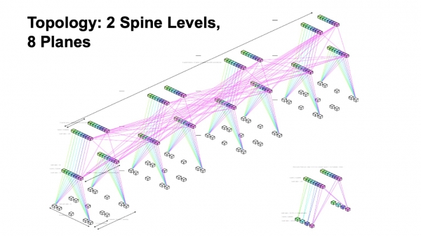
In summary, we are building on a topology with two levels of spines and eight layers of the fabric.
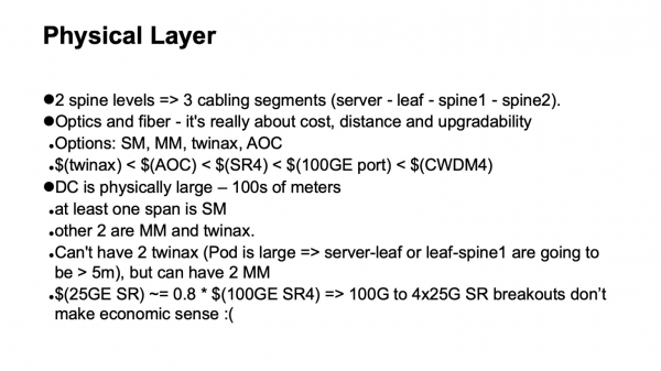
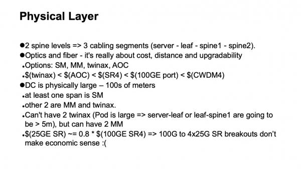
What about the physics? Very simple calculations. If we have two levels of spines, that gives us a total of three levels of switches, and we expect the network to have three cable segments: from servers to leaf switches, to spine 1, to spine 2. The options we can use are twinax, multimode, and single mode. Here, we need to consider the available bandwidth, the costs, the physical sizes, the spans we can traverse, and how we will upgrade.
In terms of cost, everything can be lined up. Twinax cables are significantly cheaper than active optics, cheaper than multimode transceivers if viewed per span from the end, a bit cheaper than a 100-gigabit switch port. And, mind you, it costs less than single mode optics because in spans where single mode is required, it makes sense to use CWDM in data centers for a number of reasons; working with parallel single mode (PSM) is not very convenient, leading to very large bundles of fiber, and if we stick to these technologies, we get approximately such a hierarchy of prices.
One more remark: unfortunately, using disaggregated 100 to 4x25 multimode ports doesn't work out very well. Due to the design features of the SFP28 transceivers, it costs almost the same as the QSFP28 at 100 Gbps. And this disaggregation does not work well for multimode.
Another limitation is that due to the size of the computational clusters and the number of servers, our data centers end up being physically large. This means that at least one span will need to be configured with single-mode. Again, due to the physical size of the Pods, it's not possible to go through two spans of twinax (copper cables).
As a result, if we optimize for cost and take into account the geometry of this structure, we get one span with twinax, one span with multimode, and one span with single-mode using CWDM. This accounts for potential upgrade pathways.
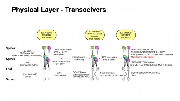
This is roughly how it looks—what has recently been, where we are heading, and what is possible. It's clear, at least, how to move towards 50-gigabit SerDes for both multimode and single-mode. Moreover, if we look at the current single-mode transceivers and the prospects for 400G, often, even when 50G SerDes come from the electrical side, the optics could already push out 100 Gbps per lane. Therefore, it is quite possible that instead of transitioning to 50, there will be a transition to 100-gigabit SerDes and 100 Gbps per lane, as many vendors expect their availability quite soon. The period when 50G SerDes were the fastest seems not to be long-lasting, as the first samples of 100G SerDes will roll out almost next year. After some time, they may also become reasonably priced.
Another nuance regarding the choice of physics is that, in principle, we can already use 400- or 200-gigabit ports with 50G SerDes. However, it turns out that there is not much sense in this because, as I mentioned earlier, we want a sufficiently large radix on the switches, within reasonable limits, of course. We want 128. And if the chip capacity is limited and we increase the link speed, then the radix, naturally, decreases—there are no miracles.
We can increase the overall capacity through planes, and there are no special costs associated with this; we can add the number of planes. However, if we lose the radix, we will need to introduce an additional level. Therefore, under the current conditions, with the maximum available capacity per chip, it turns out that it is more efficient to use 100-gigabit ports because they allow for a greater radix.
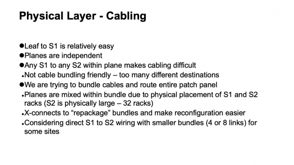
The next question is how the physics is organized, but from the perspective of the cabling infrastructure. It turns out that it is organized quite amusingly. The cabling between the leaf switches and first-level spine switches is relatively straightforward, as there aren't many links; everything is built quite simply. However, if we take one plane, what happens internally is that we need to connect all the first-level spines to all the second-level spines.
Additionally, there are usually certain preferences regarding how this should look inside the data center. For example, we really wanted to bundle cables and run them in such a way that one high-density patch panel would connect entirely to another patch panel, preventing a mishmash of different lengths. We managed to solve this problem. Initially, looking at the logical topology, one can see that the planes are independent, and each plane can be built on its own. But when we add such bundling and want to pull an entire patch panel into another patch panel, we have to mix different planes within one bundle and introduce an intermediate structure in the form of optical cross-connects to repackage them from how they were assembled in one segment to how they will be assembled in another segment. This gives us a nice feature: all the complex switching does not extend beyond the racks. When something needs to be heavily intertwined, or 'unfold the planes' as it is sometimes called in Clos networks, it is all concentrated within one rack. We do not have highly disassembled switching, down to individual links, between racks.
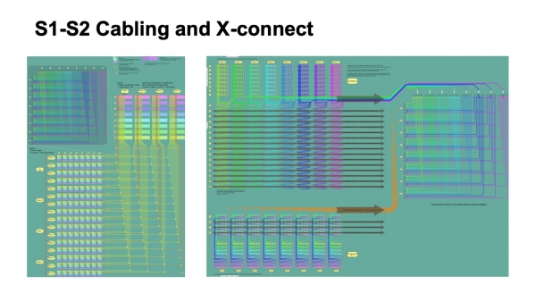
This is how it looks from the perspective of the logical organization of the cabling infrastructure. In the picture on the left, the colored blocks represent the first-level spine switches, eight of each, and the four bundles of cables running from them, which intersect with the bundles coming from the spine-2 switches.
The small squares indicate intersections. In the upper left, there is an illustration of each intersection, which is actually a 512-port cross-connect module that repackages cables to arrive completely in one rack, where only one spine-2 plane is present. To the right, there is a slightly more detailed illustration relevant to several Pods at the spine-1 level, and how this is packed in the cross-connect, as it arrives at the spine-2 level.
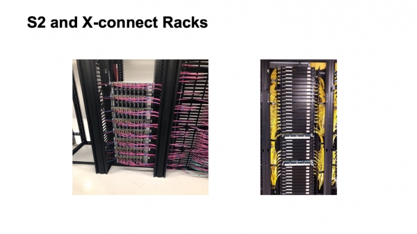
This is how it looks. A not fully assembled spine-2 rack (on the left) and the cross-connect rack. Unfortunately, not much is visible there. This entire structure is currently being deployed in one of our large data centers that is expanding. It's a work in progress, it will look better, and it will be filled out more effectively.
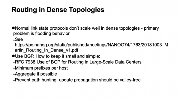
An important question: we chose the logical topology and built the physical layer. What will happen with the control plane? It is well-known from operational experience that there are several remarks suggesting that link state protocols are good and pleasant to work with, but unfortunately, they do not scale well in a densely connected topology. There is one main factor that hinders this — how flooding works in link state protocols. If you just take the flooding algorithm and look at how our network is structured, you can see that at each step there would be a very large fanout, flooding the control plane with updates. Specifically, such topologies with the traditional flooding algorithm in link state protocols mix very poorly.
The choice is to use BGP. How to prepare it correctly is described in RFC 7938 concerning the use of BGP in large data centers. The basic ideas are simple: a minimal number of prefixes per host and generally a minimal number of prefixes in the network, using aggregation if possible, and suppressing path hunting. We want very careful, very controlled propagation of updates, known as valley free. We want updates, when traversing the network, to unfold exactly once. If they originate at the bottom, they go up, unfolding no more than once. There should be no zigzags. Zigzags are very bad.
To achieve this, we use a fairly simple scheme to utilize the basic mechanisms of BGP. This means we use eBGP operating on link local, and autonomous systems are assigned as follows: an autonomous system on ToR, an autonomous system for the entire block of spine-1 switches of one Pod, and a common autonomous system for the entire Top of Fabric. It's not hard to see that even the normal behavior of BGP gives us the propagation of updates that we desire.
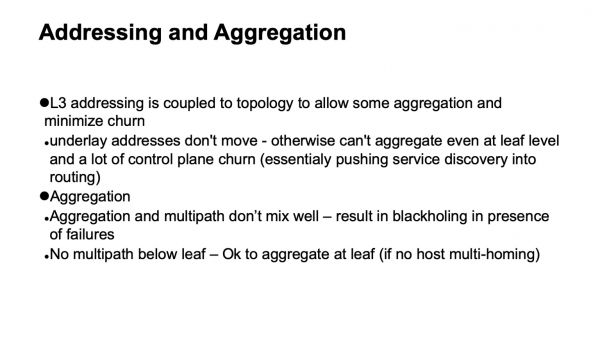
Naturally, we have to design addressing and address aggregation to be compatible with how routing is constructed, ensuring the stability of the control plane. L3 addressing in the transport layer is tied to topology, because without this aggregation cannot be achieved; individual addresses will sneak into the routing system. Another thing is that aggregation unfortunately does not mix well with multi-path, because when we have multi-path and aggregation, everything works well when the entire network is operational and has no failures. Unfortunately, as soon as failures occur in the network and the symmetry of the topology is lost, we can end up at a point from which the aggregate was announced, but cannot proceed further to where we need to go. Therefore, aggregation is best done where there is no further multi-path, in our case, this is on ToR switches.
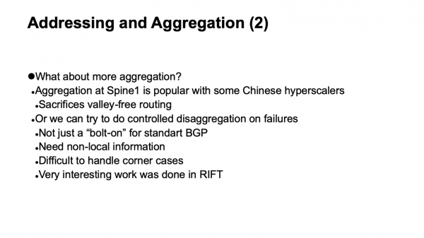
In fact, aggregation can be done, but cautiously. If we can achieve controlled de-aggregation in the event of network failures. But this is quite a complex task; we even estimated whether it could be done, if additional automation can be implemented, and finite state machines that will correctly interact with BGP to obtain the desired behavior. Unfortunately, handling corner cases is very non-obvious and complex, and by attaching external equipment to BGP, this task is not well solved.
Very interesting work has been done in this regard within the RIFT protocol, which will be discussed in the next presentation.
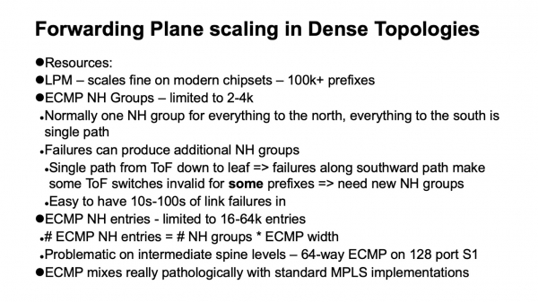
Another important aspect is how data planes scale in dense topologies, where we have a large number of alternative paths. Several additional data structures are used: ECMP groups that describe in turn groups of Next Hop.
In a well-functioning network, without failures, when we move up in a Clos topology, it is sufficient to use just one group, because anything that is not local is described by the default, allowing us to move upward. When we move downwards to the south, all paths are not ECMP; these are single-path routes. Everything is fine. The problem, and the peculiarity of classic Clos topology, is that if we look at the Top of Fabric, any element has only one path to any element below. If failures occur along this path, then that specific element at the top of the fabric becomes invalid for those prefixes lying along the broken path. For the others, it remains valid, and we have to dissect the ECMP groups and introduce a new state.
What does data plane scalability look like on modern devices? If we perform LPM (longest prefix match), it works quite well, above 100k prefixes. If we talk about Next Hop groups, it’s not so good, around 2-4 thousand. When we discuss the table that contains descriptions of Next Hops (or adjacencies), it ranges from about 16k to 64k. This can become a problem. And here we come to an interesting digression: what happened to MPLS in data centers? Essentially, we wanted to implement it.
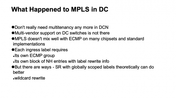
Two things happened. We implemented micro-segmentation on hosts, which made it unnecessary to do so on the network. Support from different vendors was not very good, especially with open implementations on white boxes with MPLS. Moreover, MPLS, at least its traditional implementations, unfortunately, does not integrate well with ECMP. And that is the reason.
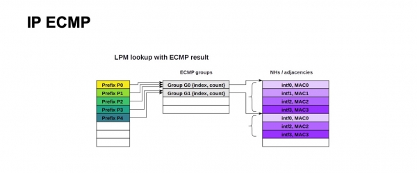
This is how the structure of ECMP forwarding for IP looks. A large number of prefixes can use the same group and the same block of Next Hops (or adjacencies, which may have different names in various documentation for different devices). The essence is that it is described as an outgoing port and what to rewrite the MAC address to in order to reach the correct Next Hop. For IP, everything looks straightforward; you can use a very large number of prefixes for the same group, using the same block of Next Hops.
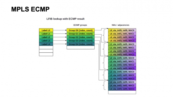
The classic MPLS architecture implies that depending on the outgoing interface, the label can be rewritten to different values. Therefore, we need to maintain a group and a block of Next Hops for each incoming label. Unfortunately, this does not scale.
It's not hard to see that we needed about 4000 ToR switches in our design, with a maximum width of 64 ECMP paths, if we move from spine-1 to spine-2. We just barely fit, at the limit, into one ECMP group table, only if one prefix with ToR is used, and we definitely cannot fit into the Next Hops table.
All is not lost, because architectures like Segment Routing imply global labels. Formally, we could condense all these Next Hops blocks again. For this, a wild card operation would be needed: taking a label and rewriting it to the same one without a specific value. Unfortunately, this is not very present in the available implementations.
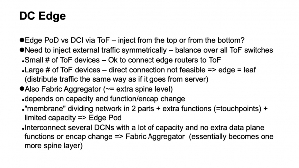
Finally, we need to bring external traffic to the data center. How do we do this? Previously, traffic was brought into the Clos network from above. There were border routers that connected to all the devices at the Top of fabric. This solution works quite well for small and medium sizes. Unfortunately, to symmetrically bring traffic into the entire network this way, we need to connect to all Top of fabric elements simultaneously, and when they exceed a hundred, it turns out we need a large radix on the border routers as well. Overall, this costs money because border routers are more functional, and the ports on them tend to be more expensive, resulting in not a very elegant structure.
Another option is to bring traffic in from below. It is not hard to see that the Clos topology is built in such a way that traffic coming from below, that is, from the ToR side, is evenly distributed across levels to the entire Top of fabric in two iterations, fully loading the entire network. Therefore, we introduce a special type of Pod, the Edge Pod, which ensures external connectivity.
There is another option. For example, Facebook does this. They call it Fabric Aggregator or HGRID. An additional spine layer is introduced to connect several data centers. Such a structure is possible if we do not have additional functions or encapsulation changes at the junctions. If they exist, these are additional touch points, which complicate things. Typically, more functions arise, and there’s a kind of membrane separating different parts of the data center. It's not worth making such a membrane large, but if absolutely necessary, it makes sense to consider moving it, making it as wide as possible, and relocating it to the hosts. This is done, for instance, by many cloud operators. They have overlays that start from the hosts.
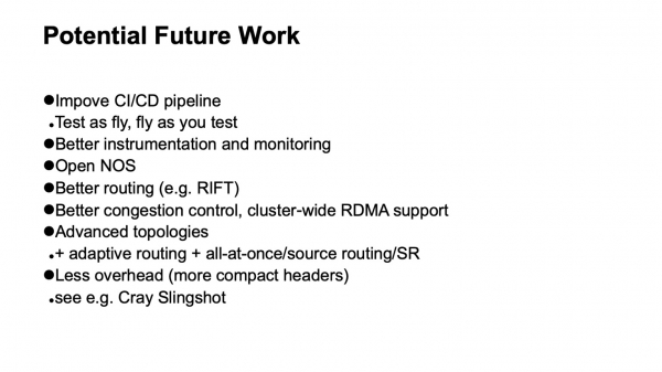
What development opportunities do we see? First and foremost — improving the support for the CI/CD pipeline. We want to fly as we test and test as we fly. This doesn't work out very well because the infrastructure is large, and duplicating it for tests is impossible. We need to understand how to introduce testing elements into the operational infrastructure without bringing it down.
Better instrumentation and better monitoring are hardly ever unnecessary. The whole question is about balancing effort and return. If reasonable efforts can be added, that would be excellent.
Open operating systems for network devices. The best protocols and routing systems, such as RIFT. Research is also needed on applying the best congestion control schemes and possibly introducing, at least at some points, support for RDMA within the cluster.
If we look towards the more distant future, advanced topologies and possibly networks using less overhead will be needed. Recently, there were publications about fabric technology for HPC Cray Slingshot, which is based on commodity Ethernet but with the option of using much shorter headers. As a result, overhead is reduced.
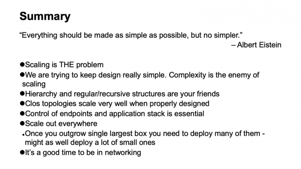
Everything should be done as simply as possible, but not simpler. Complexity is the enemy of scalability. Simplicity and regular structures are our friends. If you can scale out somewhere, do it. Overall, it's a great time to work on networking technologies. A lot of interesting things are happening. Thank you.
Source: habr.com
