

The task of increasing the communication range with an unmanned aerial vehicle (UAV) does not lose its relevance. This article discusses methods to improve this parameter. The article was written for developers and operators of UAVs and is a continuation of a series of articles about communication with UAVs (for the beginning of the cycle, see .
What affects the communication range
Communication range depends on the modem used, antennas, antenna cables, radio wave propagation conditions, external interference and some other reasons. In order to determine the degree of influence of one or another parameter on the communication range, consider the range equation
(1)

where
 — desired communication range [meters];
 is the speed of light in vacuum [m/sec];
 — frequency [Hz];
 — modem transmitter power [dBm];
 — transmitter antenna gain [dBi];
 — loss in the cable from the modem to the transmitter antenna [dB];
 — receiver antenna gain [dBi];
 — loss in the cable from the modem to the receiver antenna [dB];
 — modem receiver sensitivity [dBm];
 — attenuation multiplier that takes into account additional losses due to the influence of the Earth's surface, vegetation, atmosphere and other factors [dB].
It can be seen from the equation that the range is determined by:
- modem used;
- radio channel frequency;
- applied antennas;
- losses in cables;
- influence on the propagation of radio waves of the Earth's surface, vegetation, atmosphere, buildings, etc.
Further, the parameters affecting the range are considered separately.
Modem used
The communication range depends only on two parameters of the modem: transmitter power  and receiver sensitivity
  , or rather, from their difference - the energy budget of the modem
(2)

In order to increase the communication range, it is necessary to choose a modem with a large value  . Increase
  in turn, by increasing
  or by reducing
  . Preference should be given to searching for modems with high sensitivity (
 as low as possible), rather than increasing the transmitter power
  . This issue is discussed in detail in the first article. .
In addition to materials it is worth bearing in mind that individual manufacturers, such as Microhard , indicate in the specifications of some devices not the average, but the peak power of the transmitter, which is several times greater than the average and which cannot be used to calculate the range, since this will lead to a strong excess of the calculated range of the true value. Such devices include, for example, the popular pDDL2450 module [,]. This fact directly follows from the results of testing this device, performed to obtain an FCC certificate. (see page 58). Test results for FCC-certified wireless devices can be viewed on the FCC ID website. , by typing in the search bar the appropriate FCC ID, which should be on the label with the type designation of the device. The FCC ID of the pDDL2450 module is NS916pDDL2450.
Radio channel frequency
From the range equation it clearly follows that the lower the operating frequency  , the longer the communication range
  . But let's not rush to conclusions. The fact is that other parameters included in the equation also depend on the frequency. For example, antenna gains
  и
и  will depend on the frequency in the case when the maximum dimensions of the antennas fixedwhich is exactly what happens in practice. Antenna Gain
  , expressed in dimensionless units (times), can be expressed in terms of the physical area of the antenna
  follows
(3)

where  - antenna aperture efficiency, i.e. the ratio of the effective area of \uXNUMXb\uXNUMXbthe antenna to the physical one (depends on the design of the antenna) .
Of it is immediately clear that for a fixed antenna area, the gain increases in proportion to the square of the frequency. Substitute в , having previously rewritten using dimensionless units for antenna gains  ,
,  , cable losses
  ,
,  and attenuation multiplier
  , and also using Watts for
  и
и  instead of dBm. Then
(4)

where coefficient  is a constant for fixed antenna dimensions. Thus, in this situation, the communication range is directly proportional to the frequency, i.e. the higher the frequency, the greater the range. Output. With fixed dimensions of the antennas, an increase in the frequency of the radio link leads to an increase in the communication range due to the improvement of the directional properties of the antennas. However, it must be borne in mind that with increasing frequency, the attenuation of radio waves in the atmosphere, caused by gases, rain, hail, snow, fog and clouds, also increases. . Moreover, as the path length increases, the attenuation in the atmosphere also increases. For this reason, for each path length and average weather conditions on it, there is a certain maximum carrier frequency value, limited by the allowable level of signal attenuation in the atmosphere. Let us leave the final decision on the influence of the frequency of the radio channel on the communication range until the section where the influence of the Earth's surface and the atmosphere on the propagation of radio waves will be considered.
Antennas
The communication range is determined by such an antenna parameter as the gain  (gain in English terminology), measured in dBi. Gain is an important composite parameter because it takes into account: (1) the ability of an antenna to focus transmitter energy in the direction of a receiver compared to an isotropic radiator (isotropic, hence the index i in dBi); (2) losses in the antenna itself [,]. To increase the communication range, one should choose antennas with the highest possible gain value from those that are suitable in terms of weight and size parameters and the capabilities of the guidance system. The ability of an antenna to focus energy is not given free of charge, but only by increasing the dimensions (aperture) of the antenna. For example, the larger the receiving antenna, the larger the area it can collect energy to supply to the input of the receiver, and the more energy, the stronger the received signal, i.e., the communication range increases. Thus, you must first determine the maximum dimensions of the antennas that are adequate to the problem being solved and limit the search area to this parameter, and then search for a specific antenna model, focusing on the maximum gain. The second parameter of the antenna, important for practice, is the beam width (DN) (beamwidth) [,], measured in angular degrees. Typically, the RP width is defined as the angle between two spatial directions from the center of the antenna at which the antenna gain is reduced by 3 dB from the maximum for that antenna. The AP width in azimuth and elevation can vary greatly. This parameter is closely related to the dimensions of the antenna according to the rule: more dimensions - less width of the pattern. This parameter is not directly included in the range equation, but it is it that determines the requirements for the guidance system of the ground station (NS) antenna on the UAV, since the NS, as a rule, uses highly directional antennas, at least in cases where the range is maximized communications with UAVs is a priority. Indeed, while the tracking system of the National Assembly provides the angular accuracy of pointing the antenna to the UAV, equal to half the width of the pattern or less, then the level of the received / emitted signal will not fall below 3 dB from the maximum. Half the width of the AP of the selected antenna, under no circumstances, should be less than the angular error of the NS antenna pointing system in azimuth or elevation.
Cables
To maximize the communication range, it is necessary to use cables with the lowest possible attenuation per unit length (cable attenuation or cable loss) on working frequency of the radio link NS - UAV. Cable attenuation per unit length is defined as the ratio of the signal at the output of a 1 m long cable segment (in the metric system) to the signal at the input of the cable segment, expressed in dB. Losses in cables  , included in the range equation , are determined by multiplying the attenuation per unit length by the cable length. Thus, to obtain the maximum possible communication range, it is necessary to use cables with the lowest possible attenuation per unit length and minimize the length of these cables. On the NS, modem units must be installed directly on the mast next to the antennas. In the body of the UAV, the modem should be located as close as possible to the antennas. Separately, it is worth checking the impedance of the selected cable. This parameter is measured in ohms and is usually 50 or 75 ohms. The impedance of the cable, the modem's antenna connector, and the connector on the antenna itself must be equal.
Influence of the Earth's surface
In this section, we will consider the propagation of radio waves over a plain or sea surface. This situation is often encountered in the practice of using UAVs. UAV monitoring of pipelines, power lines, agricultural crops, many military and special operations - all this is well described by this model. Human experience paints us a picture in which communication between objects is possible if they are in the field of direct optical visibility of each other, otherwise communication is impossible. However, radio waves do not belong to the optical range, so the situation is somewhat different with them. In this regard, it is useful for the UAV developer and operator to remember the following two facts.
1. Communication in the radio range is also possible in the absence of direct visibility between the NS and the UAV.
2. The influence of the underlying surface on communication with the UAV will be felt even when there are no objects on the optical line of the NS-UAV.
To understand the specifics of the propagation of radio waves near the surface of the Earth, it is useful to familiarize yourself with the concept of a significant region of propagation of radio waves. . In the absence of any objects in a significant radio wave propagation zone, the range calculation can be performed using the formulas for free space, i.e.  в can be taken equal to 0. If there are objects in the essential zone, then this cannot be done. On fig. 1 at point A shows a point emitter located at a height
  above the surface of the Earth, which radiates electromagnetic energy in all directions with the same intensity. At point B at height height
  there is a receiver for measuring the field intensity. In this model, the significant radio wave propagation region is an ellipsoid with foci at points A and B.
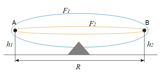
Rice. 1. Significant area of propagation of radio waves
The radius of the ellipsoid in its “thickest” part is determined by the expression
(5)

Of it's clear that  depends on frequency
  inversely proportional to the smaller
  , the "thicker" the ellipsoid (
 in fig. 1). In addition, the "thickness" of the ellipsoid increases with increasing distance between communication objects. For radio waves
  can be quite impressive, so when
  10 km
10 km  2.45 GHz we get
  50÷60 m.
Consider now an opaque object depicted by a gray triangle in Fig. 1. It will affect the propagation of radio waves with a frequency  , since it is located in a significant propagation zone, and will practically not affect the propagation of radio waves with a frequency
  . For radio waves of the optical range (light), the value
  is small, so the influence of the Earth's surface on the propagation of light is not felt in practice. Considering that the surface of the Earth is a sphere, it is easy to understand that with increasing distance
  , the underlying surface will move more and more into a significant propagation zone, thus blocking the flow of energy from point A to point B - the end of the story, communication with the UAV is interrupted. Similarly, communication will be affected by other objects on the track, such as uneven terrain, buildings, forests, etc.
Consider now Fig. 2 in which an opaque object completely covers a significant area of propagation of a radio wave with a frequency  , making it impossible to communicate on that frequency. At the same time, communication on the frequency
  still possible because part of the energy "jumps" over an opaque object. The lower the frequency, the farther beyond the optical horizon the radio wave can propagate, maintaining a stable connection with the UAV.
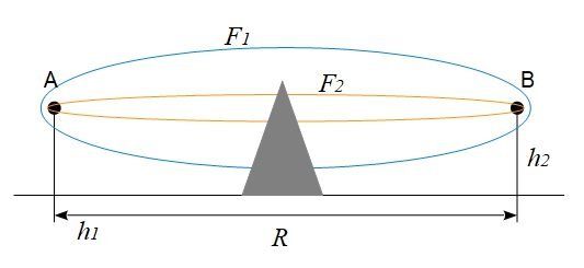
Rice. 2. Coverage of a significant area of radio wave propagation
The degree of influence of the Earth's surface on communication also depends on the height of the antennas.  и
и  . The greater the height of the antennas, the greater the distance points A and B can be moved apart, preventing objects or the underlying surface from entering the significant zone.
As the object or underlying surface moves into the significant zone, the field strength at point B will oscillate , i.e., it will be either more or less than the average field strength. This happens due to the reflection of energy from the object. The reflected energy can add up at point B with the main energy in phase - then a rise occurs in the field strength, or in antiphase - then a decline (and quite deep) occurs in the field strength. It is important to keep this effect in mind in order to understand the specifics of communication with UAVs. The loss of communication with the UAV at a certain distance can be caused by a local drop in the field strength due to oscillations, i.e. if you fly some more distance, then the connection can be restored. The final loss of communication will occur only after the significant zone is completely covered by objects or the underlying surface. Next, methods will be proposed to deal with the consequences of field strength oscillations.
Formulas for Calculating the Attenuation Multiplier  when propagating radio waves over the smooth surface of the Earth are quite complex, especially for distances
  , exceeding the range of the optical horizon . Therefore, in the further consideration of the problem, we will resort to mathematical modeling using the author's set of computer programs. Consider a typical task of transmitting video from a UAV to a satellite using a 3D Link modem from Geoscan. The initial data are as follows.
1. NS antenna suspension height: 5 m.
2. UAV flight altitude: 1000 m.
3. Radio link frequency: 2.45GHz.
4. NS antenna gain: 17 dB.
5. UAV antenna gain: 3dB.
6. Transmitter power: +25 dBm (300 mW).
7. Speed in the video channel: 4 Mbps.
8. Receiver sensitivity in the video channel: −100.4 dBm (for a frequency band occupied by a 12 MHz signal).
9. Underlying surface: dry soil.
10. Polarization: vertical.
The line-of-sight distance for these initial data will be 128.8 km. The results of calculations in the form of signal power at the input of the modem receiver in dBm are shown in fig. 3.
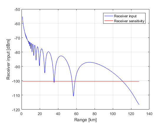
Rice. 3. Signal strength at the input of the 3D Link modem receiver
The blue curve in fig. 3 is the signal power at the input of the NS receiver, the red straight line indicates the sensitivity of this receiver. The X-axis shows the range in km, the Y-axis shows the power in dBm. At those range points where the blue curve lies above the red one, direct video reception from the UAV is possible, otherwise there will be no connection. It can be seen from the graph that, due to oscillations, communication will be lost in the range of 35.5–35.9 km and further in the range of 55.3–58.6 km. In this case, the final disconnection of the connection will come much further - after 110.8 km of flight.
As mentioned above, the dips in the field strength occur due to the addition in antiphase at the location of the NS antenna of the direct signal and the signal reflected from the Earth's surface. You can get rid of the loss of communication on the NS due to failures by fulfilling 2 conditions.
1. Use a modem on the NS with at least two receive channels (RX diversity), for example 3D Link .
2. Place the receiving antennas on the NS mast on different height.
The height spacing of the receiving antennas should be such that dips in field strength at one antenna location are compensated for by levels higher than the receiver sensitivity at the other antenna location. On fig. Figure 4 shows the result of this approach for the case where one NS antenna is located at a height of 5 m (solid blue curve) and the other at a height of 4 m (dashed blue curve).
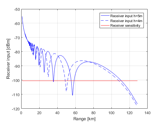
Rice. Fig. 4. Signal strength at the inputs of two 3D Link modem receivers from antennas located at different heights
From fig. 4 clearly shows the fruitfulness of this method. Indeed, over the entire distance of the UAV flight, up to a range of 110.8 km, the signal at the input of at least one NS receiver exceeds the sensitivity level, i.e., the video from the board will not be interrupted throughout the entire flight distance.
The proposed method, however, helps to increase the reliability of the UAV → NS radio link only, since the ability to install antennas at different heights is only available on the NS. It is not possible to ensure the separation of antennas along the height of 1 m on UAVs. To improve the reliability of the NS→UAV radio link, the following approaches can be used.
1. Apply the signal of the NS transmitter to the antenna that receives a more powerful signal from the UAV.
2. Use space-time codes, such as the Alamouti code .
3. Use the antenna directional control technology (beamforming) with the ability to control the power of the signal sent to each of the antennas.
The first method is close to optimal in the problem of communication with UAVs. It is simple and in it all the energy of the transmitter is directed in the right direction - to the optimally located antenna. For example, at a distance of 50 km (see Fig. 4), the transmitter signal is fed into an antenna suspended at 5 meters, and at a distance of 60 km - into an antenna suspended at 4 meters. This is the method used in the 3D Link modem. . The second method does not use a priori data on the state of the UAV → NS communication channel (levels of received signals at the antenna outputs), therefore it divides the transmitter energy equally between two antennas, which inevitably leads to energy losses, since one of the antennas may be in a hole field strength. The third method is equivalent to the first one in terms of communication quality, but it is much more complicated to implement.
Let us further consider the issue of the influence of the frequency of radio waves on the communication range with the UAV, taking into account the influence of the underlying surface. It was shown above that increasing the frequency is beneficial, because with fixed antenna dimensions, this leads to an increase in the communication range. However, the issue of dependency  frequency was not considered. From it follows that the ratio of the gains of antennas equal in area and designed to operate at frequencies
  и
и  , equals
(6)

For  2450 MHz;
  915 MHz we get
  7.2 (8.5 dB). This is exactly what happens in practice. Compare, for example, the parameters of the following antennas from Wireless Instruments:
- WiBOX PA 0809-8V [13] (frequency: 0.83–0.96 GHz; beamwidth: 70°/70°; gain: 8 dBi);
- WiBOX PA 24-15 [14] (frequency: 2.3–2.5 GHz; beamwidth: 30°/30°; gain: 15 dBi).
It is convenient to compare these antennas, since they are made in the same cases 27x27 cm, i.e. they have the same area. Note that the antenna gain differs by 15−8=7 dB, which is close to the calculated value of 8.5 dB. It can also be seen from the characteristics of the antennas that the width of the antenna pattern for the range of 2.3–2.5 GHz (30°/30°) is more than twice narrower than the width of the antenna pattern for the range of 0.83–0.96 GHz (70°/70°), i.e. The gain of the antennas with the same dimensions really increases due to the improvement of the directional properties. Taking into account the fact that 2 antennas are used in the communication line, the ratio  will be 2∙8.5=17 dB. Thus, with the same dimensions of the antennas, the energy budget of the radio link with the frequency
  2450 MHz will be 17 dB more than the line budget with frequency
  915 MHz. In the calculation, we also take into account the fact that, as a rule, whip antennas are used on UAVs for which the dimensions are not as critical as for the considered NS panel antennas. Therefore, we accept the UAV antenna gains for frequencies
  и
и  equal. Those. the difference in the energy budgets of the lines will be 8.5 dB, not 17 dB. The results of the calculation performed for these initial data and the height of the NS antenna suspension of 5 m are shown in fig. 5.
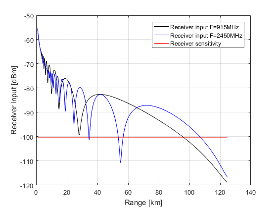
Rice. 5. Signal power at the receiver input for radio links operating at frequencies of 915 and 2450 MHz
From fig. Figure 5 clearly shows that the communication range with an increase in the operating frequency and the same area of the NS antenna increases from 96.3 km for a radio link with a frequency of 915 MHz to 110.8 km for a line with a frequency of 2450 MHz. However, the line at 915 MHz has a lower oscillation frequency. Fewer oscillations means fewer dips in field strength, i.e. less chance of interrupting communication with the UAV over the entire flight distance. Perhaps it is this fact that determines the popularity of the sub-GHz range of radio waves for command-telemetry communication lines with UAVs as the most reliable. At the same time, when performing the above-described set of actions to protect against field strength oscillations, the gigahertz radio links provide a longer communication range by improving the directional properties of the antennas.
From the consideration of Fig. 5, we can also conclude that in the shadow zone (after the mark of 128.8 km), lowering the operating frequency of the communication line makes sense. Indeed, at about −120 dBm, the power curves for frequencies  и
и  intersect. Those. when using receivers with a sensitivity better than -120 dBm, a radio link at a frequency of 915 MHz will provide a greater communication range. In this case, however, the required bandwidth of the link must be taken into account, since for such a high sensitivity value, the information rate will be very small. For example, 3D Link modem although it provides sensitivity up to -122 dBm, but the aggregate (both directions) information transfer rate will be 23 kbit / s, which, in principle, is sufficient for CTRL communication with UAVs, but is clearly not enough for transmitting video from the board. Thus, the subGHz range, indeed, has a slight advantage over the GHz range for KTRL, but clearly loses in performance when organizing video lines.
When choosing the frequency of the radio link, it is also necessary to take into account the attenuation of the signal during propagation in the Earth's atmosphere. For NS-UAV communication links, attenuation in the atmosphere is caused by gases, rain, hail, snow, fog and clouds . For operating frequencies of radio links below 6 GHz, attenuation in gases can be neglected . The strongest attenuation is observed in rains, especially high intensity (showers). Table 1 shows the data attenuation specific [dB/km] in rain of different intensity for frequencies 3-6 GHz.
Table 1. Specific attenuation of radio waves [dB/km] in rains of different intensity depending on the frequency
Frequency [GHz]
3 mm/hour (weak)
12 mm/hour (moderate)
30mm/hour (strong)
70 mm/hour (shower)
3.00
0.3∙10−3
1.4∙10−3
3.6∙10−3
8.7∙10−3
4.00
0.3∙10−2
1.4∙10−2
3.7∙10−2
9.1∙10−2
5.00
0.8∙10−2
3.7∙10−2
10.6∙10−2
28∙10−2
6.00
1.4∙10−2
7.1∙10−2
21∙10−2
57∙10−2
From Table. It follows from Table 1 that, for example, at a frequency of 3 GHz, the attenuation in the shower will be about 0.0087 dB/km, which on a path of 100 km will give 0.87 dB of the total attenuation. With an increase in the operating frequency of the radio link, the attenuation in the rain increases sharply. For a frequency of 4 GHz, the attenuation in a shower on the same path will already be 9.1 dB, and at frequencies of 5 and 6 GHz it will be 28 and 57 dB, respectively. In this case, however, it is assumed that rain with a given intensity takes place throughout the route, which rarely happens in practice. However, when using the UAV in areas where heavy rains are frequent, it is recommended to select the operating frequency of the radio link below 3 GHz.
Literature
1. Smorodinov A.A. Habr. 2019.
2. Kalinin A.I., Cherenkova E.L. Propagation of radio waves and the operation of radio links. Connection. Moscow. 1971.
3.
4.
5.
6.
7.
8. C. A. Balanis. antenna theory. Analysis and design. Fourth edition. John Wiley & Sons. 2016.
9. Article in Wikipedia.
10. Article in Wikipedia.
11.
12. S. M. Alamouti. "A simple transmit diversity technique for wireless communications". IEEE Journal on Selected Areas in Communications. 16(8): 1451–1458.
13.
14.
Source: habr.com
