

Introduction
The article was prompted by the disheartening frequency of questions on this topic in specialized groups within the Russian-speaking Telegram community. It is aimed at beginner administrators of Mikrotik RouterOS (hereafter ROS). The focus is solely on MultiWAN with an emphasis on routing. As a bonus, it includes the minimum necessary configurations to ensure safe and convenient operations. Those looking for in-depth discussions on queues, load balancing, VLANs, bridges, and multi-step deep analysis of channel states should refrain from reading further.
Source Data
For this purpose, a five-port Mikrotik router running ROS version 6.45.3 has been selected. It will route traffic between two local networks (LAN1 and LAN2) and three ISPs (ISP1, ISP2, ISP3). The channel to ISP1 has a static 'grey' IP address, ISP2 has a 'white' IP received via DHCP, and ISP3 has a 'white' IP with PPPoE authorization. The connection diagram is shown in the image:
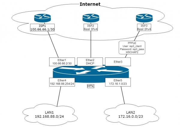
The task is to configure the router 'MTK' based on the diagram so that:
- Automatic switching to a backup provider is ensured. The primary provider is ISP2, the first backup is ISP1, and the second backup is ISP3.
- The LAN1 network is to access the Internet only through ISP1.
- Traffic from local networks to the Internet should be routed through the selected provider based on the address-list.
- The setup should allow publishing services from the local network to the Internet (DSTNAT).
- A firewall filter is to be configured to provide minimal adequate security from the Internet.
- The router should be able to send its own traffic through any of the three providers, depending on the selected source address.
- Ensure routing of return packets through the channel they came from (including LAN).
Note. We will configure the router 'from scratch' to guarantee no surprises from startup configurations that change from version to version 'out of the box'. Winbox will be used as the configuration tool, where changes will be visually displayed. The configurations themselves will be input through commands in the Winbox terminal. Physical connection for configuration will be made via a direct connection to the Ether5 interface.
A few reflections on what a multivan is, whether it's a problem, or if clever people are weaving webs of conspiracies around it.
An inquisitive and attentive admin, while configuring such or a similar scheme, suddenly realizes that it's working just fine. Yes, without all those user-defined routing tables and other route rules that most articles on this topic are cluttered with. Shall we check?
Can we configure addressing on the interfaces and default gateways? Yes:
On ISP1 we specified the address and gateway with distance=2 and check-gateway=ping.
On ISP2, the default DHCP client setting — therefore distance will be one.
On ISP3 in the PPPoE client settings, with add-default-route=yes we set default-route-distance=3.
Don't forget to set up NAT for external access:
/ip firewall nat add action=masquerade chain=srcnat out-interface-list=WAN
As a result, users in local networks can joyfully connect through the primary provider ISP2, with channel redundancy using the check gateway See note 1
Item 1 of the task is implemented. Where is the multivan with its tags? No...
Next. We need to route specific clients from LAN through ISP1:
/ip firewall mangle add action=route chain=prerouting dst-address-list=!BOGONS
passthrough=yes route-dst=100.66.66.1 src-address-list=Via_ISP1
/ip firewall mangle add action=route chain=prerouting dst-address-list=!BOGONS
passthrough=no route-dst=100.66.66.1 src-address=192.168.88.0/24
Items 2 and 3 of the task are implemented. Tags, marks, route rules, where are you?!
Do we need to provide access to the favorite OpenVPN server with the address 172.17.17.17 for clients from the Internet? Here you go:
/ip cloud set ddns-enabled=yes
For clients as peers, we provide the output result: “:put [ip cloud get dns-name]”
Setting up port forwarding from the internet:
/ip firewall nat add action=dst-nat chain=dstnat dst-port=1194
in-interface-list=WAN protocol=udp to-addresses=172.17.17.17
Item 4 is ready.
We configure the firewall and other security measures for item 5, while also enjoying the fact that users already have everything working and reaching for a container of our favorite drink...
Oh! We almost forgot the tunnels.
Has the L2TP client, set up according to a Googled article, connected to the beloved Dutch VDS? Yes.
Has the L2TP server with IPsec been set up and are clients connecting by DNS name from IP Cloud (see above)? Yes.
Leaning back in the chair, sipping a drink, we lazily consider items 6 and 7 of the task. We think — do we even need this? Everything seems to work as is... So if it really isn't necessary, that's it. The multivan is implemented.
What is a multivan? It's the connection of multiple internet channels to a single router.
After this, the article can be skipped, because what else could there be apart from some questionable show-off?
With those who remain, who are interested in points 6 and 7 of the task, and who feel the itch of perfectionism, we dive deeper.
The most important task in implementing the multihoming strategy is the correct routing of traffic. Specifically: regardless of which (or which) provider channel the default route on our router is looking at, it should return the response precisely to the channel from which the packet originated. The task is clear. But where’s the problem? In a simple local network, the task is the same, yet no one gets tangled up in extra configurations and doesn’t feel any trouble. The difference lies in the fact that any routable node on the Internet is accessible through each of our channels, not just a specific one like in a simple local network. The
The solution will be divided into three stages:
- Preliminary settings. At this stage, the basic settings of the router will be established: local network, firewall, address lists, hairpin NAT, etc.
- Multihoming. At this stage, the necessary connections will be tagged and sorted into routing tables.
- Connection to ISP. At this stage, the interfaces ensuring the connection to the Internet will be configured, routing will be activated, and the mechanism for backup Internet channels will be established.
1. Preliminary settings
1.1. Clear the router configuration using the command:
/system reset-configuration skip-backup=yes no-defaults=yesagreeing with "Dangerous! Reset anyway? [y/N]:" and, after rebooting, connect via Winbox using MAC. At this stage, the configuration and user database are cleared.
1.2. Create a new user:
/user add group=full name=knight password=ultrasecret comment=”Not horse”log in under it and remove the default user:
/user remove adminNote. The author believes that deleting, rather than disabling, the default user is safer and recommends it.
1.3. Create basic interface lists for easy operation in the firewall, discovery settings, and other MAC servers:
/interface list add name=WAN comment="For Internet"
/interface list add name=LAN comment="For Local Area"
Add comments to the interfaces
/interface ethernet set ether1 comment="to ISP1"
/interface ethernet set ether2 comment="to ISP2"
/interface ethernet set ether3 comment="to ISP3"
/interface ethernet set ether4 comment="to LAN1"
/interface ethernet set ether5 comment="to LAN2"
and fill in the interface lists:
/interface list member add interface=ether1 list=WAN comment=ISP1
/interface list member add interface=ether2 list=WAN comment=ISP2
/interface list member add interface=ether3 list=WAN comment="to ISP3"
/interface list member add interface=ether4 list=LAN  comment="LAN1"
/interface list member add interface=ether5 list=LAN  comment="LAN2"
Note. Writing clear comments is worth the time spent and greatly eases troubleshooting and understanding of the configuration.
The author believes it is necessary, for security reasons, to add the ether3 interface to the WAN interface list, even though it will not carry the IP protocol.
Don't forget that once the PPP interface is activated on ether3, it will also need to be added to the WAN interface list.
1.4. Hiding the router from detection and management from provider networks using MAC:
/ip neighbor discovery-settings set discover-interface-list=!WAN
/tool mac-server set allowed-interface-list=LAN
/tool mac-server mac-winbox set allowed-interface-list=LAN
1.5. Creating a minimally sufficient set of firewall filter rules to protect the router:
/ip firewall filter add action=accept chain=input comment="Related Established Untracked Allow"
connection-state=established,related,untracked
(this rule allows established and related connections initiated from both connected networks and the router itself)
/ip firewall filter add action=accept chain=input comment="ICMP from ALL" protocol=icmp(ping and not just ping. All ICMP is allowed in. It is very useful for finding MTU issues)
/ip firewall filter add action=drop chain=input comment="All other WAN Drop" in-interface-list=WAN(the closing input chain rule denies everything else that comes from the Internet)
/ip firewall filter add action=accept chain=forward
comment="Established, Related, Untracked allow"
connection-state=established,related,untracked
(this rule allows established and related connections that pass through the router)
/ip firewall filter add action=drop chain=forward comment="Invalid drop" connection-state=invalid(this rule drops connections with connection-state=invalid that pass through the router. It is highly recommended by Mikrotik, but in some rare situations, it may block useful traffic)
/ip firewall filter add action=drop chain=forward comment="Drop all from WAN not DSTNATed"
connection-nat-state=!dstnat connection-state=new in-interface-list=WAN
(this rule denies packets from the Internet that did not go through the dstnat procedure from passing through the router. This will protect local networks from attackers who, being in the same broadcast domain as our external networks, will set our external IPs as gateways and thus try to 'explore' our local networks.)
Note. Let’s assume that LAN1 and LAN2 networks are trusted and traffic between them and from them is not filtered.
1.6. Creating a list of non-routable networks:
/ip firewall address-list
add address=0.0.0.0/8 comment=""This" Network" list=BOGONS
add address=10.0.0.0/8 comment="Private-Use Networks" list=BOGONS
add address=100.64.0.0/10 comment="Shared Address Space. RFC 6598" list=BOGONS
add address=127.0.0.0/8 comment=Loopback list=BOGONS
add address=169.254.0.0/16 comment="Link Local" list=BOGONS
add address=172.16.0.0/12 comment="Private-Use Networks" list=BOGONS
add address=192.0.0.0/24 comment="IETF Protocol Assignments" list=BOGONS
add address=192.0.2.0/24 comment=TEST-NET-1 list=BOGONS
add address=192.168.0.0/16 comment="Private-Use Networks" list=BOGONS
add address=198.18.0.0/15 comment="Network Interconnect Device Benchmark Testing"
 list=BOGONS
add address=198.51.100.0/24 comment=TEST-NET-2 list=BOGONS
add address=203.0.113.0/24 comment=TEST-NET-3 list=BOGONS
add address=224.0.0.0/4 comment=Multicast list=BOGONS
add address=192.88.99.0/24 comment="6to4 Relay Anycast" list=BOGONS
add address=240.0.0.0/4 comment="Reserved for Future Use" list=BOGONS
add address=255.255.255.255 comment="Limited Broadcast" list=BOGONS
(This is a list of addresses and networks that are not routed to the Internet, and accordingly, we will also adhere to this.)
Note. The list may change, so I recommend periodically checking its relevance.
1.7. Configuring DNS for the router itself:
/ip dns set servers=1.1.1.1,8.8.8.8Note. In the current version of ROS, dynamic servers have priority over statically assigned ones. The name resolution request is sent to the first server in the list. The next server is used if the current one is unavailable. The timeout is large — over 5 seconds. There is no automatic return when the 'failed server' resumes operation. Considering this algorithm and the presence of multipath, the author recommends not to use servers provided by ISPs.
1.8. Setting up the local network.
1.8.1. Configuring static IP addresses on local network interfaces:
/ip address add interface=ether4 address=192.168.88.254/24 comment="LAN1 IP"
/ip address add interface=ether5 address=172.16.1.0/23 comment="LAN2 IP"
1.8.2. Defining routing rules to our local networks through the main routing table:
/ip route rule add dst-address=192.168.88.0/24 table=main comment=”to LAN1”
/ip route rule add dst-address=172.16.0.0/23 table=main comment="to LAN2"
Note. This is one of the simple and quick ways to access the addresses of local networks with sources from the external IP addresses of the router interfaces, through which there is no default route.
1.8.3. Enabling Hairpin NAT for LAN1 and LAN2:
/ip firewall nat add action=src-nat chain=srcnat comment="Hairpin to LAN1"
out-interface=ether4 src-address=192.168.88.0/24 to-addresses=192.168.88.254
/ip firewall nat add action=src-nat chain=srcnat comment="Hairpin to LAN2"
out-interface=ether5 src-address=172.16.0.0/23 to-addresses=172.16.1.0
Note. This allows access to your resources (dstnat) using the external IP, while being inside the network.
2. The actual implementation of the correct multipath
To solve the task of 'responding from where it was asked', we will use two ROS tools: connection mark and routing mark. Connection mark allows you to label the desired connection and subsequently work with this label as a condition for application routing mark. And then, you can work with routing mark ip route route rules and . Now that we have understood the tools, we need to determine which connections to mark — first, and where exactly to mark them — second.The first part is simple — we need to mark all connections arriving at the router from the Internet via the corresponding channel. In our case, these will be three labels (one for each channel): 'conn_isp1', 'conn_isp2', and 'conn_isp3'.
The nuance with the second part is that incoming connections will be of two types: transit and those intended for the router itself. The connection mark mechanism operates in the
mangle table. Let’s look at the movement of a packet in a simplified diagram, kindly assembled by specialists from mikrotik-trainings.com (no advertisement):Following the arrows, we see that the packet arriving at the '
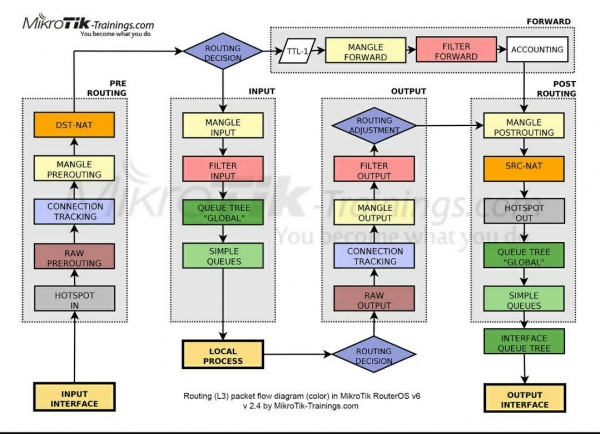
input interface' passes through the 'Prerouting' chain and only then is split into transit and local in the 'Routing Decision' block. Therefore, to achieve two goals, we will involveConnection Mark in the Mangle Prerouting chain. chains ' chain and only then is split into transit and local in the '.
NoteIn ROS, the labels 'Routing mark' are specified in the section Ip/Routes/Rules as 'Table', while in other sections, they are referred to as 'Routing Mark'. This might cause some confusion in understanding, but essentially they are the same and are analogous to rt_tables in iproute2 on Linux.
2.1. We tag incoming connections from each of the providers:
/ip firewall mangle add action=mark-connection chain=prerouting
comment="Connmark in from ISP1" connection-mark=no-mark in-interface=ether1  new-connection-mark=conn_isp1 passthrough=no

/ip firewall mangle add action=mark-connection chain=prerouting
comment="Connmark in from ISP2" connection-mark=no-mark in-interface=ether2  new-connection-mark=conn_isp2 passthrough=no

/ip firewall mangle add action=mark-connection chain=prerouting
comment="Connmark in from ISP3" connection-mark=no-mark in-interface=pppoe-isp3  new-connection-mark=conn_isp3 passthrough=no
Note. To avoid tagging already tagged connections, I use the condition connection-mark=no-mark instead of connection-state=new, as I find this to be more correct, just as I opt out of dropping invalid connections in the input filter.
passthrough=no — because in this implementation method, re-tagging is excluded and to speed up, we can terminate the rule matching after the first match.
It should be noted that we are not yet interfering with routing. Currently, only preparation stages are underway. The next stage of implementation will involve processing transit traffic that returns through an established connection from the recipient in the local network. That is, those packets which (see diagram) passed through the router on the path:
"Input Interface" => "Prerouting" => "Routing Decision" => "Forward" => "Post Routing" => "Output Interface" and reach their destination in the local network.
Important! In ROS, there is no logical division between external and internal interfaces. If we trace the path of the response packet through the provided diagram, it will follow the same logical path as the request:
"Input Interface" => "Prerouting" => "Routing Decision" => "Forward" => "Post Routing" => "Output Interface" simply the interface for the request "Input Interface" was the ISP interface, while for the response it was the LAN.
2.2. We direct the response transit traffic through the appropriate routing tables:
/ip firewall mangle add action=mark-routing chain=prerouting
comment="Routemark transit out via ISP1" connection-mark=conn_isp1
dst-address-type=!local in-interface-list=!WAN new-routing-mark=to_isp1 passthrough=no

/ip firewall mangle add action=mark-routing chain=prerouting
comment="Routemark transit out via ISP2" connection-mark=conn_isp2
dst-address-type=!local in-interface-list=!WAN new-routing-mark=to_isp2 passthrough=no

/ip firewall mangle add action=mark-routing chain=prerouting
comment="Routemark transit out via ISP3" connection-mark=conn_isp3
dst-address-type=!local in-interface-list=!WAN new-routing-mark=to_isp3 passthrough=no
Note. in-interface-list=!WAN — we are only working with traffic from the local network and dst-address-type=!local, which does not have the destination address of the router's interfaces.
The same applies to local packets that came to the router via the path:
"Input Interface" => "Prerouting" => "Routing Decision" => "Input" => "Local Process"
Important! The response will follow this path:
"Local Process" => "Routing Decision" => "Output" => "Post Routing" => "Output Interface"
2.3. We direct the response local traffic through the corresponding routing tables:
/ip firewall mangle add action=mark-routing chain=output
comment="Routemark local out via ISP1" connection-mark=conn_isp1 dst-address-type=!local
new-routing-mark=to_isp1 passthrough=no

/ip firewall mangle add action=mark-routing chain=output
comment="Routemark local out via ISP2" connection-mark=conn_isp2 dst-address-type=!local
new-routing-mark=to_isp2 passthrough=no

/ip firewall mangle add action=mark-routing chain=output
comment="Routemark local out via ISP3" connection-mark=conn_isp3 dst-address-type=!local
new-routing-mark=to_isp3 passthrough=no
At this stage, the task of preparing the response to be sent back through the Internet channel from which the request came can be considered resolved. Everything is tagged, marked, and ready for routing.
An excellent "side" effect of this configuration is the ability for DSNAT port forwarding to work with both (ISP2, ISP3) providers simultaneously. Not on all, as ISP1 has a non-routable address. This effect is important, for example, for a mail server with two MX records looking into different Internet channels.
To address the nuances of local networks with external router IPs, we use solutions from sections 1.8.2 and 3.1.2.6.
Additionally, we can employ a tool with tags to solve point 3 of the task. We will implement it as follows:
2.4. We direct traffic from local clients from the routing lists to the corresponding tables:
/ip firewall mangle add action=mark-routing chain=prerouting
comment="Address List via ISP1" dst-address-list=!BOGONS new-routing-mark=to_isp1
passthrough=no src-address-list=Via_ISP1

/ip firewall mangle add action=mark-routing chain=prerouting
comment="Address List via ISP2" dst-address-list=!BOGONS new-routing-mark=to_isp2
passthrough=no src-address-list=Via_ISP2

/ip firewall mangle add action=mark-routing chain=prerouting
comment="Address List via ISP3" dst-address-list=!BOGONS new-routing-mark=to_isp3
passthrough=no src-address-list=Via_ISP3
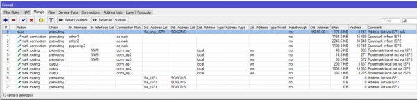
In the end, it looks approximately like this:
3. We configure the connection to the ISP and implement routing by tags
3.1. Configuring the connection to ISP1:
3.1.1. Configuring the static IP address:
/ip address add interface=ether1 address=100.66.66.2/30 comment="ISP1 IP"3.1.2. Setting up static routing:
3.1.2.1. Adding a "fallback" default route:
/ip route add comment="Emergency route" distance=254 type=blackholeNote. This route allows traffic from local processes to pass through the Route Decision stage regardless of the status of any provider's channels. The nuance of outgoing local traffic is that for a packet to move anywhere, there must be an active route to the default gateway in the main routing table. If not, the packet will simply be discarded.
As an extension of the tool check gateway for a deeper analysis of channel status, I suggest using the method of recursive routes. The essence of the method is that we instruct the router to look for a path to its gateway not directly, but through an intermediate gateway. The selected "check" gateways will be 4.2.2.1, 4.2.2.2, and 4.2.2.3 respectively for ISP1, ISP2, and ISP3.
3.1.2.2. Route to the "check" address:
/ip route add check-gateway=ping comment="For recursion via ISP1"
distance=1 dst-address=4.2.2.1 gateway=100.66.66.1 scope=10
Note. We lower the scope value to the default in ROS target scope to later use 4.2.2.1 as a recursive gateway. I emphasize: the scope of the route to the "check" address must be less than or equal to the target scope of the route that will reference the checker.
3.1.2.3. Default recursive route for traffic without a routing mark:
/ip route add comment="Unmarked via ISP1" distance=2 gateway=4.2.2.1Note. The distance=2 value is used because ISP1 is designated as the first backup according to the task conditions.
3.1.2.4. Default recursive route for traffic with the routing mark "to_isp1":
/ip route add comment="Marked via ISP1 Main" distance=1 gateway=4.2.2.1
routing-mark=to_isp1
Note. Here, we finally start to make use of the fruits of the preparatory work done in section 2.
Through this route, all traffic marked with the route 'to_isp1' will be directed to the first provider's gateway, regardless of which gateway is currently active by default for the main table.
3.1.2.5. The first backup recursive default route for the marked traffic of providers ISP2 and ISP3:
/ip route add comment="Marked via ISP2 Backup1" distance=2 gateway=4.2.2.1
routing-mark=to_isp2
/ip route add comment="Marked via ISP3 Backup1" distance=2 gateway=4.2.2.1
routing-mark=to_isp3
Note. These routes are also necessary for traffic backup from local networks, which consist of members of the address list 'to_isp*'.
3.1.2.6. Setting up the route for local router traffic to the internet through ISP1:
/ip route rule add comment="From ISP1 IP to Inet" src-address=100.66.66.2 table=to_isp1Note. Combined with the rules from section 1.8.2, this ensures access to the required channel with the specified source. This is critical for building tunnels where the local side IP address is set (EoIP, IP-IP, GRE). Since the rules in ip route rules are executed from top to bottom until the first condition is met, this rule must come after the rules from section 1.8.2.
3.1.3. Setting up a NAT rule for outgoing traffic:
/ip firewall nat add action=src-nat chain=srcnat comment="NAT via ISP1"
ipsec-policy=out,none out-interface=ether1 to-addresses=100.66.66.2
Note. NAT applies to all outgoing traffic except those that fall under IPsec policies. I try not to use action=masquerade unless absolutely necessary. It operates slower and is more resource-intensive than src-nat, as it calculates the address for NAT for every new connection.
3.1.4. Directing clients from the list who are prohibited from going through the other providers directly to the gateway of provider ISP1.
/ip firewall mangle add action=route chain=prerouting comment="Address List via ISP1 only"
dst-address-list=!BOGONS passthrough=no route-dst=100.66.66.1
src-address-list=Via_only_ISP1 place-before=0
Note. action=route has a higher priority and is applied before other routing rules.
place-before=0 — places our rule first on the list.
3.2. Configuring the connection to ISP2.
Since provider ISP2 provides us settings via DHCP, it makes sense to make the necessary changes using a script that starts when the DHCP client is triggered:
/ip dhcp-client
add add-default-route=no disabled=no interface=ether2 script=":if ($bound=1) do={r
    n    /ip route add check-gateway=ping comment="For recursion via ISP2" distance=1
           dst-address=4.2.2.2/32 gateway=$"gateway-address" scope=10r
    n    /ip route add comment="Unmarked via ISP2" distance=1 gateway=4.2.2.2;r
    n    /ip route add comment="Marked via ISP2 Main" distance=1 gateway=4.2.2.2
           routing-mark=to_isp2;r
    n    /ip route add comment="Marked via ISP1 Backup1" distance=2 gateway=4.2.2.2
           routing-mark=to_isp1;r
    n    /ip route add comment="Marked via ISP3 Backup2" distance=3 gateway=4.2.2.2
           routing-mark=to_isp3;r
    n    /ip firewall nat add action=src-nat chain=srcnat ipsec-policy=out,none
           out-interface=$"interface" to-addresses=$"lease-address" comment="NAT via ISP2"
           place-before=1;r
    n    if ([/ip route rule find comment="From ISP2 IP to Inet"] ="") do={r
    n        /ip route rule add comment="From ISP2 IP to Inet"
               src-address=$"lease-address" table=to_isp2 r
    n    } else={r
    n       /ip route rule set [find comment="From ISP2 IP to Inet"] disabled=no
              src-address=$"lease-address"r
    n    }      r
    n} else={r
    n   /ip firewall nat remove  [find comment="NAT via ISP2"];r
    n   /ip route remove [find comment="For recursion via ISP2"];r
    n   /ip route remove [find comment="Unmarked via ISP2"];r
    n   /ip route remove [find comment="Marked via ISP2 Main"];r
    n   /ip route remove [find comment="Marked via ISP1 Backup1"];r
    n   /ip route remove [find comment="Marked via ISP3 Backup2"];r
    n   /ip route rule set [find comment="From ISP2 IP to Inet"] disabled=yesr
    n}r
    n" use-peer-dns=no use-peer-ntp=no
The script itself in the Winbox window:
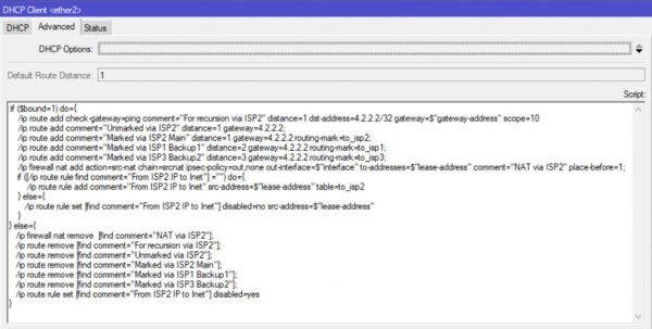
Note. The first part of the script triggers upon successful lease acquisition, the second — after lease release.See note 2
3.3. Configuring the connection to provider ISP3.
Since the provider gives us dynamic settings, it makes sense to make the necessary changes using scripts that start up after the interface ppp is brought up and after it goes down.
3.3.1. First, we configure the profile:
/ppp profile
add comment="for PPPoE to ISP3" interface-list=WAN name=isp3_client
on-down="/ip firewall nat remove  [find comment="NAT via ISP3"];r
    n/ip route remove [find comment="For recursion via ISP3"];r
    n/ip route remove [find comment="Unmarked via ISP3"];r
    n/ip route remove [find comment="Marked via ISP3 Main"];r
    n/ip route remove [find comment="Marked via ISP1 Backup2"];r
    n/ip route remove [find comment="Marked via ISP2 Backup2"];r
    n/ip route rule set [find comment="From ISP3 IP to Inet"] disabled=yes;"
on-up="/ip route add check-gateway=ping comment="For recursion via ISP3" distance=1
    dst-address=4.2.2.3/32 gateway=$"remote-address" scope=10r
    n/ip route add comment="Unmarked via ISP3" distance=3 gateway=4.2.2.3;r
    n/ip route add comment="Marked via ISP3 Main" distance=1 gateway=4.2.2.3
    routing-mark=to_isp3;r
    n/ip route add comment="Marked via ISP1 Backup2" distance=3 gateway=4.2.2.3
    routing-mark=to_isp1;r
    n/ip route add comment="Marked via ISP2 Backup2" distance=3 gateway=4.2.2.3
    routing-mark=to_isp2;r
    n/ip firewall mangle set [find comment="Connmark in from ISP3"]
    in-interface=$"interface";r
    n/ip firewall nat add action=src-nat chain=srcnat ipsec-policy=out,none
    out-interface=$"interface" to-addresses=$"local-address" comment="NAT via ISP3"
    place-before=1;r
    nif ([/ip route rule find comment="From ISP3 IP to Inet"] ="") do={r
    n   /ip route rule add comment="From ISP3 IP to Inet" src-address=$"local-address"
    table=to_isp3 r
    n} else={r
    n   /ip route rule set [find comment="From ISP3 IP to Inet"] disabled=no
    src-address=$"local-address"r
    n};r
    n"
The script itself in the Winbox window:
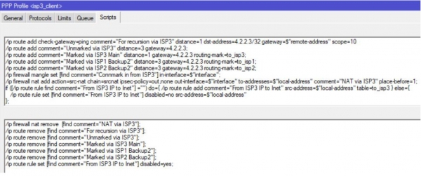
Note. Line
/ip firewall mangle set [find comment=«Connmark in from ISP3»] in-interface=$«interface»;
allows for the correct handling of interface renaming, as it works with its code rather than the displayed name.
3.3.2. Now, using the profile, we create a ppp connection:
/interface pppoe-client add allow=mschap2 comment="to ISP3" disabled=no
interface=ether3 name=pppoe-isp3 password=isp3_pass profile=isp3_client user=isp3_client
As the last touch, let's configure the clock:
/system ntp client set enabled=yes server-dns-names=0.pool.ntp.org,1.pool.ntp.org,2.pool.ntp.orgFor those who have read to the end
The proposed implementation method for multipath is a personal preference of the author and is not the only possible one. The ROS toolkit is extensive and flexible, which can be challenging for beginners but is also the reason for its popularity. Explore, experiment, and discover new tools and solutions for yourself. For example, in this multipath implementation, the tool could be replaced by Check-gateway with recursive routes to Netwatch.
Notes
- Check-gateway is a mechanism that allows the deactivation of a route after two consecutive failed gateway availability checks. The check is performed every 10 seconds, plus a response timeout. Thus, the actual switch timing ranges from 20 to 30 seconds. If this switching timing is not sufficient, there is an option to use the tool Netwatch, where the check timer can be set manually. The mechanism Check-gateway does not trigger during periodic packet losses in the channel.
Important! Deactivating the main route entails deactivating all other routes that reference it. Therefore, it is unnecessary to specify check-gateway=ping .
- Sometimes, there is a malfunction in the DHCP mechanism that appears as the client getting stuck in a renew state. In this case, the second part of the script will not execute, but allowing traffic to flow correctly will not be hindered, as the state is monitored by the corresponding recursive route.
- ECMP (Equal Cost Multi-Path) there is an option in ROS to set up a route with multiple gateways and the same distance. In this case, connections will be distributed across the channels using a round-robin algorithm, proportional to the number of specified gateways.
A personal thanks to Evgeny for the push to write the article, help in forming its structure and highlighting key points.
Source: habr.com
