


This article is a continuation , dedicated to the specifics of configuring equipment Palo Alto Networks . Here we want to discuss the configuration of IPSec Site-to-Site VPN on the equipment Palo Alto Networks and a possible configuration option for connecting multiple Internet providers.
To demonstrate, a standard scheme for connecting the head office to the branch will be used. To ensure a fault-tolerant Internet connection, the head office utilizes simultaneous connections with two providers: ISP-1 and ISP-2. The branch is connected to a single provider, ISP-3. Two tunnels are established between firewalls PA-1 and PA-2. The tunnels operate in Active-Standby, with Tunnel-1 active, and Tunnel-2 will start transmitting traffic upon the failure of Tunnel-1. Tunnel-1 uses the connection to Internet provider ISP-1, while Tunnel-2 uses the connection to Internet provider ISP-2. All IP addresses are randomly generated for demonstration purposes and do not relate to reality.
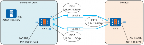
To build the Site-to-Site VPN, the IPSec set of protocols for securing data transmitted over IP will be used. IPSec It will operate using the security protocol ESP (Encapsulating Security Payload), which will ensure the encryption of transmitted data.
In IPSec includes IKE (Internet Key Exchange) is the protocol responsible for negotiating SA (security associations), the security parameters used to protect transmitted data. PAN firewalls support IKEv1 and IKEv2.
In IKEv1 The VPN connection is built in two phases: IKEv1 Phase 1 (IKE tunnel) and IKEv1 Phase 2 (IPSec tunnel), thus creating two tunnels, one of which is used for exchanging control information between the firewalls, while the other is for traffic transmission. In IKEv1 Phase 1 there are two operational modes—main mode and aggressive mode. Aggressive mode uses fewer messages and operates faster, but does not support Peer Identity Protection.
IKEv2 replaced it, and compared to IKEv1, its main advantage is lower bandwidth requirements and faster SA negotiation. In IKEv1 fewer control messages are used (only 4), the EAP protocol is supported, MOBIKE is included, and a mechanism for checking the availability of the peer with which the tunnel is created— IKEv2 Liveness Check , replacing Dead Peer Detection in IKEv1. If the check fails, then, replacing Dead Peer Detection in IKEv1. If the check fails, then IKEv2 can drop the tunnel and then automatically restore it at the first opportunity. More details about the differences can be .
If the tunnel is established between firewalls from different manufacturers, there may be bugs in the implementation IKEv2, and for compatibility with such equipment, there is an option to use IKEv1. In other cases, it is better to use IKEv2.
Configuration steps:
• Configuring two internet providers in ActiveStandby mode
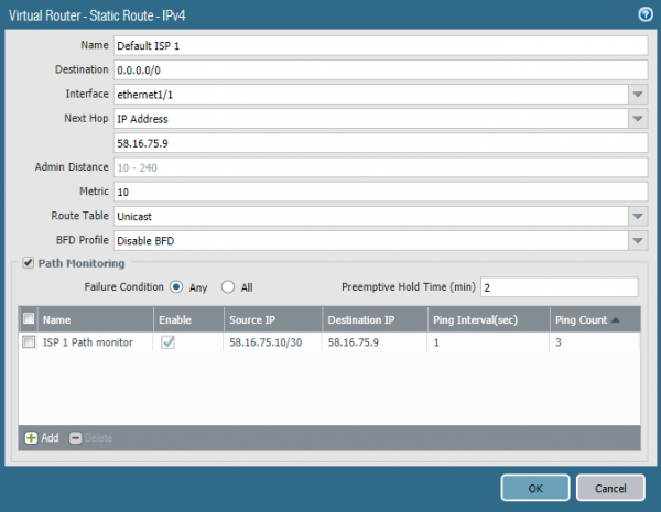
There are several ways to implement this function. One of them involves using the mechanism of Path Monitoring, which became available starting with version PAN-OS 8.0.0. In this example, version 8.0.16 is used. This function is similar to IP SLA in Cisco routers. The static default route parameter is configured to send ping packets to a specific IP address from a specified source address. In this case, the ethernet1/1 interface pings the default gateway once per second. If there are no responses for three consecutive pings, the route is considered non-functional and is removed from the routing table. A similar route is configured towards the second internet provider, but with a higher metric (it is a backup). As soon as the first route is removed from the table, the firewall will start sending traffic through the second route — Fail-Over. When the first provider starts responding to pings, its route will return to the table and replace the second one due to the better metric — Fail-Back. The process Fail-Over takes a few seconds depending on the configured intervals, but, in any case, the process is not instantaneous, and during this time traffic is lost. Fail-Back occurs without traffic loss. It is possible to make Fail-Over faster, with the help of BFD, if the internet provider provides such an opportunity. BFD is supported starting from the model PA-3000 Series and VM-100. As an address for pinging, it is better to specify a public, always accessible internet address rather than the provider’s gateway.
• Creating a tunnel interface
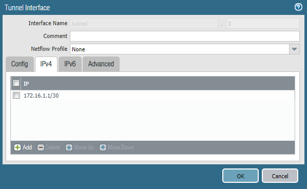
Traffic inside the tunnel is transmitted through special virtual interfaces. Each of them must be configured with an IP address from the transit network. In this example, subnet 172.16.1.0/30 will be used for Tunnel-1, and subnet 172.16.2.0/30 for Tunnel-2.
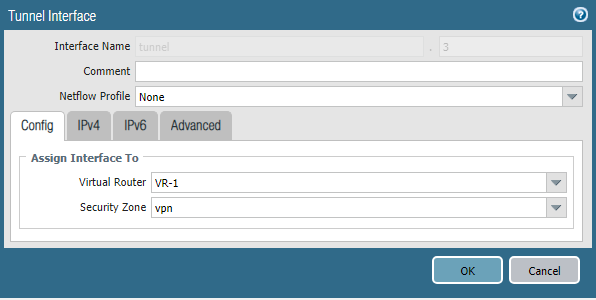
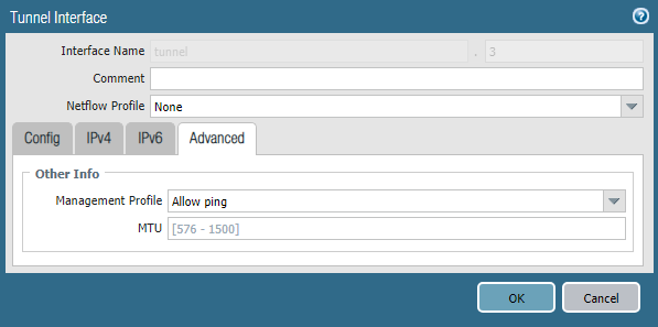
The tunnel interface is created in the section Network -> Interfaces -> TunnelYou need to specify a virtual router and a security zone, as well as an IP address from the corresponding transport network. The interface number can be any.
In the section Advanced you can specify Management Profile, which will allow pinging this interface; this can be useful for testing.
• Configuring IKE Profile
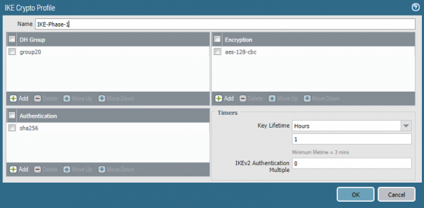
IKE Profile is responsible for the first phase of establishing a VPN connection where tunnel parameters are specified. IKE Phase 1. The profile is created in the section Network -> Network Profiles -> IKE Crypto. You need to specify the encryption algorithm, hashing algorithm, Diffie-Hellman group, and key lifetime. Generally, the more complex the algorithms, the worse the performance, so they should be selected based on specific security requirements. However, it is strongly discouraged to apply a Diffie-Hellman group lower than 14 for protecting sensitive information. This is due to protocol vulnerabilities that can only be mitigated by using 2048-bit modules or higher, or elliptic curve cryptography algorithms used in groups 19, 20, 21, 24. These algorithms offer better performance compared to traditional cryptography. . And .
• Configuring IPSec Profile
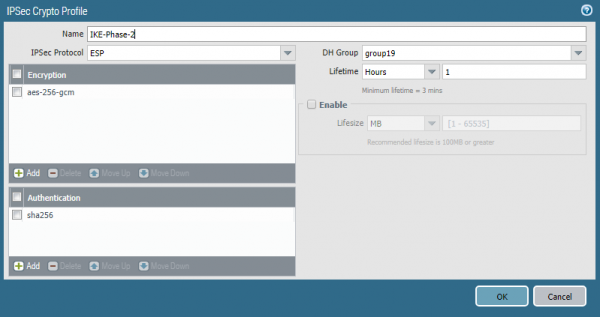
The second phase of establishing a VPN connection is the IPSec tunnel. The SA parameters for it are configured in Network -> Network Profiles -> IPSec Crypto Profile. Here you need to specify the IPSec protocol — AH or ESP, as well as the parameters SA — hashing algorithms, encryption algorithms, Diffie-Hellman groups, and key lifetime. The SA parameters in IKE Crypto Profile and IPSec Crypto Profile may not match.
• Configuring IKE Gateway
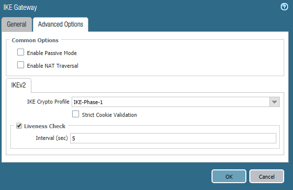
IKE Gateway is an object representing the router or firewall with which the VPN tunnel is established. For each tunnel, you need to create a separate one IKE Gateway. In this case, two tunnels are created, one through each Internet provider. The corresponding outgoing interface and its IP address, the peer IP address, and the shared key are specified. As an alternative to the shared key, certificates can be used.
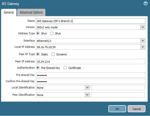
Here you specify the previously created IKE Crypto Profile. The parameters of the second object IKE Gateway are similar, except for the IP addresses. If the Palo Alto Networks firewall is located behind a NAT router, the mechanism must be enabled. NAT Traversal.
• Configuring IPSec Tunnel
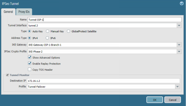
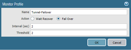
IPSec Tunnel — this is an object that specifies the parameters of the IPSec tunnel, as the name suggests. You need to indicate the tunnel interface and previously created objects here. IKE Gateway, IPSec Crypto Profile. To enable automatic routing failover to the backup tunnel, you need to enable Tunnel Monitor. This is a mechanism that checks if the peer is alive using ICMP traffic. You must specify the IP address of the tunnel interface of the peer with which the tunnel is being built as the destination address. The profile includes timers and actions upon loss of connection. Wait Recover – wait until the connection is restored, Fail Over — send traffic via another route if one exists. The configuration of the second tunnel is exactly the same, specifying the second tunnel interface and IKE Gateway.
• Routing Configuration
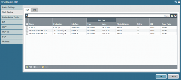
In this example, static routing is used. On the PA-1 firewall, in addition to two default routes, two routes to the subnet 10.10.10.0/24 in the branch must be specified. One route uses Tunnel-1, the other Tunnel-2. The route through Tunnel-1 is primary since it has a lower metric. The mechanism Path Monitoring for these routes is not in use. Failover is handled by Tunnel Monitor.
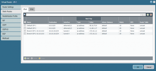
Similar routes for the subnet 192.168.30.0/24 need to be configured on PA-2.
• Network Rules Configuration
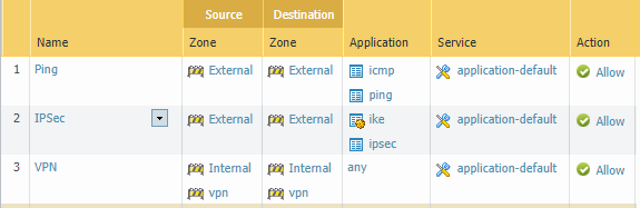
Three rules are needed for the tunnel to function:
- For operation Path Monitor allow ICMP on the external interfaces.
- For IPSec allow applications ike and ipsec on the external interfaces.
- Allow traffic between internal subnets and tunnel interfaces.
Conclusion
This article discusses the configuration option for a resilient internet connection and Site-to-Site VPN. We hope the information was useful and that the reader gained insight into the technologies used in Palo Alto Networks. If you have questions about the configuration or suggestions for future article topics, please write them in the comments; we will be happy to respond.
Source: habr.com
