

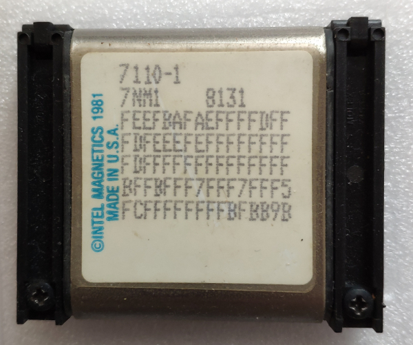
Photo from the author's collection
1. History
Bubble memory, or memory on cylindrical magnetic domains, is a non-volatile memory developed at Bell Labs in 1967 by Andrew Bobeck. Research showed that small cylindrical magnetic domains form in monocrystalline thin films of ferrites and garnets when a sufficiently strong magnetic field is applied perpendicular to the surface of the film. By changing the magnetic field, these bubbles can be moved. Such properties make magnetic bubbles an ideal medium for building a sequential storage of bits, similar to a shift register, where the presence or absence of a bubble in a specific position indicates a zero or one value of a bit. The diameter of a bubble is in the tenths of a micron, with one chip capable of storing thousands of bits of data. For example, in the spring of 1977, Texas Instruments first introduced a chip with a capacity of 92304 bits to the market. This memory is non-volatile, making it similar to magnetic tape or disk, but since it is solid-state and contains no moving parts, it offers greater reliability than tape or disk, requires no maintenance, and is much smaller and lighter, enabling its use in portable devices.
Initially, the inventor of bubble memory, Andrew Bobeck, proposed a "one-dimensional" version of the memory, in the form of a thread onto which a thin strip of ferromagnetic material was wound. This memory was called "twistor memory," and was even produced on a commercial scale, but was soon replaced by the "two-dimensional" version.
You can review the history of bubble memory creation in [1-3].
2. Principle of operation
Here I ask for forgiveness, I am not a physicist, so the explanation will be very approximate.
Some materials (for example, gadolinium-gallium garnet) have the property of being magnetized in only one direction, and if a constant magnetic field is applied along this axis, the magnetized areas will form something like bubbles, as shown in the figure below. Each bubble is only a few microns in diameter.
Imagine we have a thin, approximately 0.001 inch thick, crystalline film made of such material applied to a non-magnetic substrate, for example, glass.
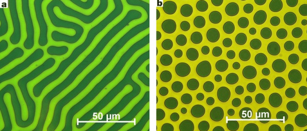
It’s all about magical bubbles. The image on the left shows the absence of a magnetic field, while the image on the right shows a magnetic field directed perpendicular to the surface of the film.
If a pattern of magnetic material, such as permalloy, an iron-nickel alloy, is created on the surface of a film made of such material, the bubbles will be attracted to the elements of this pattern. Typically, T-shaped or V-shaped elements are used.
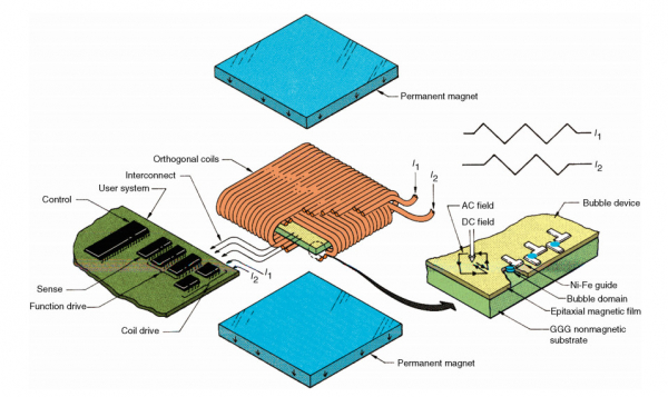
A single bubble can be formed by a magnetic field of 100-200 Oersted applied perpendicular to the magnetic film, created by a permanent magnet, while a rotating magnetic field generated by two coils in the XY directions allows bubbles-domains to move from one magnetic 'island' to another, as shown in the diagram. After four changes of direction of the magnetic field, the domain will move from one island to the adjacent one.
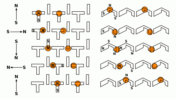
This allows us to consider the CMD device as a shift register. If we generate bubbles at one end of the register and detect them at the other, we can send a specific pattern of bubbles in a loop and use the system as a memory device, reading and writing bits at specific moments in time.
Thus, the advantages and disadvantages of CMD memory are as follows: one advantage is energy independence (as long as a perpendicular field, created by permanent magnets, is applied, the bubbles will not disappear or shift from their positions), while a disadvantage is the long access time, as accessing a randomly selected bit requires spinning the entire shift register to the desired position, and the longer it is, the more cycles this will require.
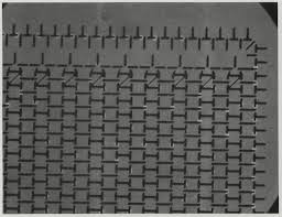
Pattern of magnetic elements on the magnetic film of CMD.
Creating a magnetic domain is called 'nucleation' in English. This involves applying a current of a few hundred milliamperes to the winding for about 100 ns, generating a magnetic field perpendicular to the film and opposite to the field of a permanent magnet. This creates a magnetic 'bubble' — a cylindrical magnetic domain in the film. Unfortunately, this process highly depends on temperature, and the recording operation may end unsuccessfully, leading to the absence of a bubble or the formation of multiple bubbles.
Various techniques are used for reading data from the film.
One method, non-destructive reading, involves detecting the weak magnetic field of the cylindrical domain using a magnetoresistive sensor.
The second method is destructive reading. The bubble is directed to a special track for generation/detection, where it is destroyed by magnetizing the material in the forward direction. If the material was magnetized in the opposite direction and the bubble was present, this will cause a larger current in the coil, which is then detected by the electronic circuit. Afterwards, the bubble must be regenerated on a special writing track.
However, if the memory is organized as a single continuous array, it has two major drawbacks. Firstly, the access time will be very long. Secondly, a single defect in the chain will lead to a complete malfunction of the entire device. Therefore, memory is structured with one main track and multiple subordinate tracks, as shown in the figure.
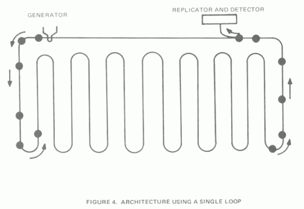
Bubble memory with a single continuous track
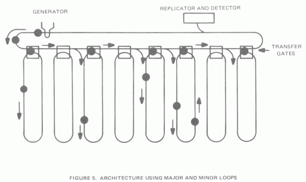
Bubble memory with main/subordinate tracks
This memory configuration not only significantly reduces access time but also allows for the production of memory devices that contain a certain number of defective tracks. The memory controller must account for these and bypass them during read/write operations.
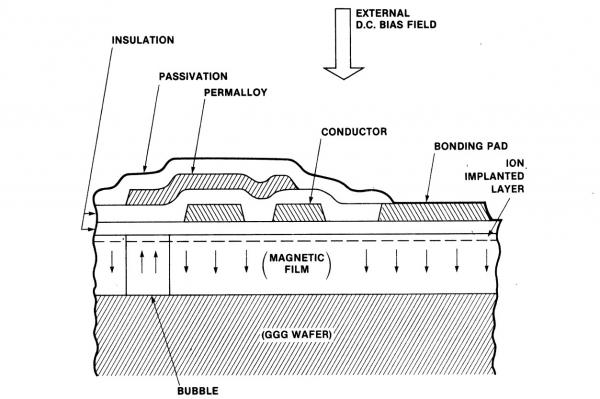
The figure below shows a cross-section of the bubble memory 'chip'.
You can also read about the principle of bubble memory operation in [4, 5].
3. Intel 7110
Intel 7110 — a magnetic bubble memory module with a capacity of 1 MB (1048576 bits). It is depicted on the KDPV. 1 megabit represents a storage capacity for user data, and considering the redundant tracks, the total capacity is 1310720 bits. The device contains 320 loop tracks, each with a capacity of 4096 bits, but only 256 of them are used for user data; the remainder serves as a reserve for replacing 'bad' tracks and for storing redundant error correction code. The device follows a 'main track-minor loop' architecture. Information about active tracks is contained in a separate bootstrap loop. On the KDPV, you can see the hexadecimal code printed directly on the module, which serves as the map of 'bad' tracks: 80 hexadecimal digits represent 320 data tracks, with active tracks represented by a '1' bit and inactive ones by a '0'.
You can find the original documentation for the module at [7].
The device features a dual-row pin configuration and is socket-mounted without soldering.
The module structure is shown in the figure:
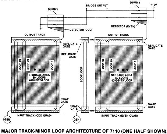
The memory array is divided into two 'half sections', each further divided into two 'quads', with each quad containing 80 subordinate tracks. The module includes a plate of magnetic material placed between two orthogonal coils that create a rotating magnetic field. For this purpose, triangular waveform current signals are applied to the coils, offset by 90 degrees relative to each other. The assembly consisting of the plate and coils is placed between permanent magnets and housed in a magnetic shield that closes the magnetic flux generated by the permanent magnets and screens the device from external magnetic fields. The plate is tilted at an angle of 2.5 degrees, creating a slight bias field along the tilt. This bias is negligible compared to the coil field and does not interfere with bubble movement during device operation; however, it shifts the bubbles into fixed positions relative to the permalloy elements when the device is off. A strong perpendicular component from the permanent magnets sustains the existence of bubble magnetic domains.
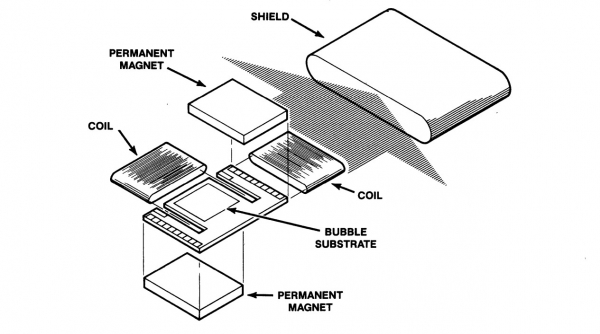
The module contains the following components:
- Memory tracks. Specifically, those tracks made of permalloy elements that hold and direct the bubbles.
- Replication generator. This serves to replicate the bubble that is constantly present at the generation point.
- Inbound track and exchange nodes. Generated bubbles move along the inbound track. Bubbles are directed into one of 80 subordinate tracks.
- Outbound track and replication node. Bubbles are read from the data tracks without destruction. The bubble is split into two parts, one of which is directed to the outbound track.
- Detector. Bubbles from the outbound track enter a magnetoresistive detector.
- Boot track. The boot track contains information about active and inactive data tracks.
Below, we will discuss these nodes in more detail. You can also find descriptions of these nodes in [6].
Bubble generation
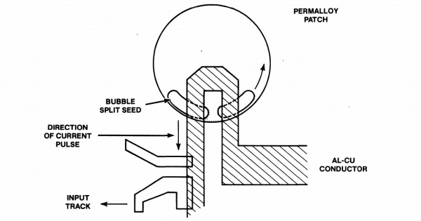
To generate a bubble, at the very beginning of the inbound track, there is a conductor bent into a tiny loop. A current pulse is supplied to it, which creates a magnetic field in a very small area stronger than that of permanent magnets. The pulse creates a bubble at this location, which remains constant, sustained by a permanent magnetic field, and circulates along the permalloy element under the influence of a rotating magnetic field. If we need to record a one in memory, we send a short pulse into the conductive loop, resulting in the birth of two bubbles (marked in the figure as Bubble split seed). One of the bubbles rushes along the permalloy track with the rotating field, while the other stays in place and quickly regains its original size. It then moves to one of the subordinate tracks and swaps places with the bubble that circulates in it. This bubble, in turn, reaches the end of the inbound track and disappears.
Bubble exchange
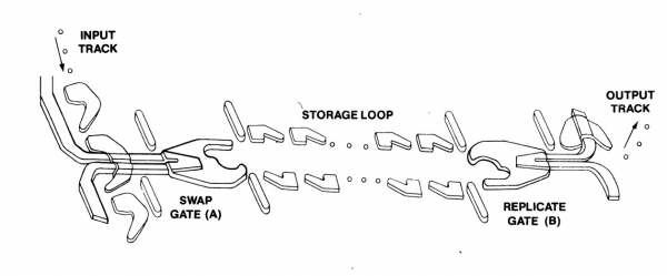
Bubble exchange occurs when a rectangular-shaped current pulse is supplied to the corresponding conductor. No splitting of the bubble into two parts occurs during this process.
Data reading
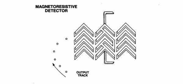
Data is sent to the output track by replication and continues to circulate in its track after reading. Thus, a non-destructive reading method is implemented in this device. For replication, a bubble is directed under an elongated permalloy element, under which it stretches. A loop-shaped conductor is also present on top; if a current pulse is applied to the loop, the bubble splits into two parts. The current pulse consists of a short section with a large current to separate the bubble into two parts and a longer section with a smaller current to direct the bubble to the output track.
At the end of the output track, there is a bubble detector, a magnetoresistive bridge made of permalloy elements forming a long chain. When the magnetic bubble comes under the permalloy element, its resistance changes, and a voltage difference appears at the output of the bridge in the millivolt range. The shape of the permalloy elements is designed so that the bubble moves along them; eventually, it reaches a special 'guard' bus and disappears.
Redundancy
The device contains 320 tracks, each with 4096 bits. Of these, 272 are active, and 48 are inactive spares.
Boot Loop
The device contains 320 data tracks, of which 256 are designated for storing user data, while the others may be faulty or serve as spares for replacing faulty ones. One additional track contains information on the usage of data tracks, with 12 bits for each track. When power is applied to the system, it must be initialized. During initialization, the controller must read the boot track and write the information from it into a special register of the formatting/current sensor chip. The controller will then use only the active tracks, while inactive ones will be ignored and not written to.
Data Storage - Structure
From the user's perspective, data is stored in 2048 pages of 512 bits each, consisting of 256 bytes of data, 14 bits of error correction code, and 2 unused bits saved in each half of the device.
Error Correction
Error detection and correction can be performed by a current sensor chip that contains a 14-bit code decoder, capable of correcting single errors up to 5 bits (burst error) in each block of 270 bits (including the code itself). The code is appended to the end of each 256-bit block. The correction code can be used or not used at the user's discretion; code checking can be enabled or disabled in the controller. If the code is not used, all 270 bits can be utilized for user data.
Access time
The magnetic field rotates at a frequency of 50 kHz. The average access time to the first bit of the first page is 41 ms, which is half the time required to complete a full cycle along the track plus the time to traverse the output track.
320 active and spare tracks are divided into four parts of 80 tracks each. This organization reduces access time. Quarters are addressed in pairs: each pair of quarters contains even and odd bits of a word, respectively. The device contains four input tracks with four initial bubbles, and four output tracks. The output tracks use two detectors, organized so that no two bubbles from two tracks reach one detector simultaneously. Thus, the four streams of bubbles are multiplexed and converted into two streams of bits, which are saved in the registers of the current sensor chip. There, the contents of the registers are multiplexed again and transmitted to the controller through a serial interface.
In the second part of the article, we will take a closer look at the circuitry of the bubble memory controller.
4. References
The author has found and preserved for you a wealth of useful technical information on CMD memory, its history, and other related aspects in the darkest corners of the web:
1. — Two Memories by Engineer Bobek
2. — Two Memories by Engineer Bobek (Part 2)
3. — Bubble Memory
4. Adaptation of Magnetic Bubble Memory in a Standard Microcomputer Environment
5. — Texas Instruments TIB 0203 Bubble Memory
6. — Memory Components Handbook. Intel 1983.
7. 7110 1-Megabit Bubble Memory
Source: habr.com
