

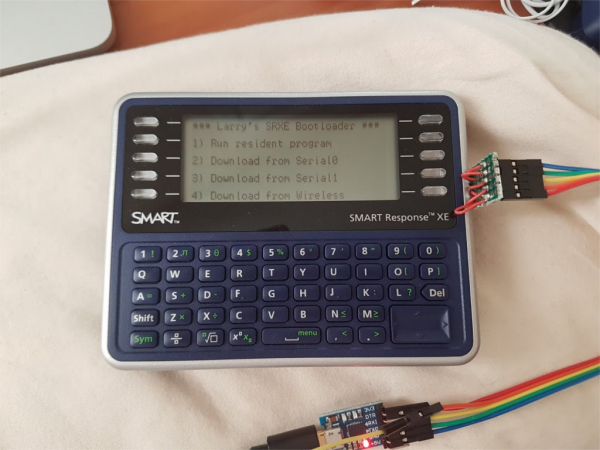
It all started with the author's purchase of an interesting device on the secondary market — Smart Response XE (). It is intended for schools: each student in the class receives a device resembling an electronic notebook or a translator from the nineties. The teacher asks a question, and students type their answers on the device's keyboards, which are transmitted via radio (802.15.4) to a receiver connected to the teacher's PC.
Support for these devices was discontinued several years ago, and what schools bought for $100-200 each now appears on eBay for $10 or less. The hardware is very suitable for geeky experiments:
- a 60-key keyboard
- a display with a resolution of 384×136, 2 bits per pixel — similar to BK, CGA, but with 4 shades of brightness instead of colors
- an ATmega128RFA1 microcontroller (128 kB flash memory, 4 kB EEPROM, 16 kB RAM, 802.15.4 transceiver)
- an external (relative to the microcontroller, not the entire device) flash memory of 1 megabit (128 kilobytes) with an SPI interface
- a compartment for 4 AAA batteries.
From the name of the microcontroller, it's clear that it belongs to the AVR family, which means making the device Arduino-compatible is a more than trivial task...
From a news piece on , the author learned that this (the same link explains what to connect where), gaining the ability to run games for Arduboy:
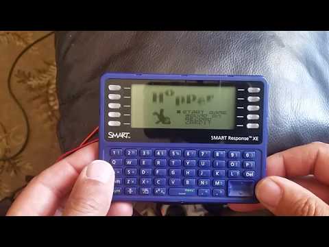
However, the author is more interested in the ability not to play on the device, but to explore:
- flash memory with a serial SPI interface
- bootloaders for AVR
- the 802.15.4 standard
The author began by writing (GPL v3), allowing to initialize the display, display text and rectangles, and access the flash memory with the SPI interface. Then he started to come up with ideas for practical uses of the device: a pocket VT-100 compatible terminal, multiplayer games. After modifying three devices, he decided to 'teach' them to receive sketches 'over the air'. This would not only be interesting but also very convenient: opening the device case is difficult each time, and under the battery compartment's cover are only holes to connect a JTAG programmer to the board.
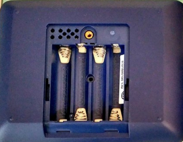
This is enough to upload the Arduino bootloader, but not the sketch — the serial port is not connected, so you can't avoid opening the case. Additionally, the TX0 and RX0 lines of the first serial port are combined with the key matrix polling lines, specifically those used for polling the function keys on either side of the display. But what can you do — the author made the following setup:
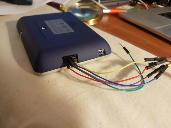
He routed the JTAG lines, so now it's not necessary to open the battery compartment. To allow sketch uploads as well, he connected both serial ports to this same connector, and also added a switch because the device cannot be physically powered off differently when the batteries are installed.
It took quite a long time working with a soldering iron, a utility knife, and a glue gun. In general, uploading sketches 'over the air' is much more convenient, so something needs to be invented urgently for this purpose.
The Arduino IDE uses the program . It communicates with the microcontroller via the protocol, which allows files to be transmitted in both directions. It is poorly compatible with channels where variable delays, distortion, and data loss are possible. If something is loose or crackling in the serial channel, you can go insane trying to find the cause. Once, the author struggled for half a day before realizing that the issue was a bad cable, along with a finicky CP2102 interface converter. Even a microcontroller with a built-in interface converter, like the ATmega32u4, can occasionally 'act up' like this. Every Arduino user has noticed that errors during sketch uploads are not uncommon. Sometimes the writing goes smoothly, but during verification, an error is discovered. This does not mean there was a mistake during writing — the failure occurred during reading. Now imagine that while working 'over the air', the same thing will happen, but much more frequently.
After trying various methods to overcome this problem, the author came up with the following solution. The device has 128-kilobyte flash memory with an SPI interface — receiving data over wires (remember, the author already has one device with a side connector), using this memory as a buffer, and sending data to another device via radio channel. A little greeting from Cybiko.
After writing the code for working with the radio channel and the font, the bootloader became longer than 4 kilobytes. Therefore, the HFUSE value had to be changed from 0xDA to 0xD8. Now, the bootloader can be up to 8 kilobytes in length, and the starting address is set to 0x1E000. This is reflected in the Makefile, but it should also be taken into account during flashing. using avrdude.
The 802.15.4 standard transceiver in the ATmega128RFA1 was originally designed to operate under the , which is quite complex, so the author decided instead to simply transmit packets. This is implemented in hardware on the ATmega128RFA1, so the code required is minimal. Additionally, for simplicity, the author chose to use a fixed channel, not allowing for manual selection. The 802.15.4 standard supports 16 channels numbered from 11 to 26. They are quite congested, with some overlapping with WiFi channels (ZigBee channels are marked in red, WiFi channels in blue, green, and yellow).

It turned out that channels 15 and 26 are least susceptible to interference from WiFi. The author chose the latter. Disclaimer: the translator does not know if simplifying ZigBee like this is permitted. Perhaps, it would be worth programming it a bit more to implement it fully?
On the first device, it is necessary to implement a finite state machine that transmits data using the STK500 protocol. Mostly, the transmitted and received messages are self-contained, but some are linked to those that have passed through the channel earlier. A description of the dialogue is provided. .
A crucial part of this dialogue is the transmission of packets intended for writing to the flash memory of the target device. For simple microcontrollers of the AVR family, the page size is 128 bytes, but for the ATmega128RFA1, it is 256. The flash memory that connects via the SPI protocol also has the same size. When uploading a sketch, the program in the first device does not send it immediately to the second, but writes it to this memory. When the Arduino IDE checks the correctness of the writing, it receives what has been written there. Now, the received data needs to be transmitted via radio channel to the second device. During this process, switching between reception and transmission happens quite frequently. The STK500 protocol is indifferent to delays, but it cannot tolerate data loss (strangely, it was mentioned earlier that delays in data transmission also have an impact). However, losses during wireless transmission are inevitable. The ATmega128RFA1 has a hardware implementation of repeat requests if there are doubts about the correctness of the transmission, but the author decided to implement the same functionality programmatically on their own. They developed a protocol where significantly more data flows one way than the other.
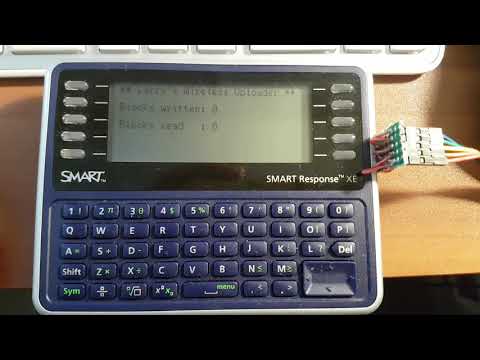
It is not perfect, but everything works. The 256-byte page is split into four segments, each of which is transmitted over the radio channel as a packet. A packet can hold up to 125 bytes of data plus one byte for length and two bytes for CRC. Thus, fragments of 64 bytes each, along with page and segment numbers (from 0 to 3), are placed there. The receiving device has a variable that allows tracking how many segments have been received, and when all four arrive, an acknowledgment is sent back to the transmitting device that the entire page has been accepted. No acknowledgment (if CRC does not match) — resend the entire page. The speed achieved is even greater than when transmitting over cable. See:
However, it would be advisable to provide a convenient way to connect the device to a cable for uploading sketches. For example, integrate an interface converter based on the CP2102, like in the photo, and attach it to the board in a way that allows it to withstand the force when connecting and disconnecting the Micro USB cable.
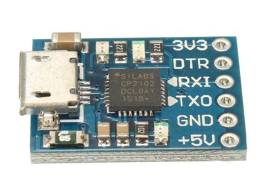
It also features a 3.3-volt regulator (and how to use it in a device powered by 6 volts — only if there's a similar regulator, and two diodes can be added to automatically choose which one the device will be powered from). You need to desolder all three LEDs from the interface converter board, otherwise they will additionally drain the batteries when powered from them, as well as interfere with keyboard polling and working with flash memory using the SPI interface.
The pursuit of the goal turned out to be even more interesting than achieving it (and let's not bring up that joke about the bus). The author learned a lot about bootloaders for AVR, flash memory with SPI interface, the STK500 protocol, and the 802.15.4 standard.
The rest of the code in addition to the library described above — , and it is also under GPL v3. The author's Twitter — .
Source: habr.com
