

Recently, colleagues in the field have independently started asking me: how to receive all Bluetooth channels at once from a single SDR receiver? The bandwidth allows it, with SDRs offering an output bandwidth of 80 MHz and more. Of course, this could be done on an FPGA, but developing that would take a considerable amount of time. I had long known that doing this on a GPU is quite simple, but to this extent!
The Bluetooth standard defines the physical layer in two versions: Classic and Low Energy. The specification is available. The document is extremely lengthy, reading it in full is risky for the brain. Fortunately, major companies producing measurement equipment have the resources to create illustrative documents on the topic. and , for example. I have absolutely no chance of competing with them in terms of presenting the material. Interested parties, please explore the links.
All I need to know about the physical layer for creating a multi-channel filter is the frequency grid step and modulation speed. These are summarized in a table in one of the referenced documents:
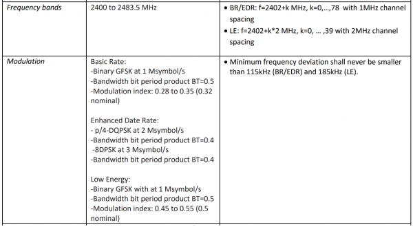
Thus, we need to segment the 80 MHz bandwidth into 79 filters with a tuning step of 1 MHz and simultaneously into 40 filters with a tuning step of 2 MHz. The sample frequency outputs from the filters should be 1 MHz and 2 MHz, respectively.
Therefore, we need two comb filters.
To start, let’s choose the parameters of these filters based on the bandwidths of Bluetooth Classic and Bluetooth Low Energy signals. We need their impulse responses to calculate the load on the filter computing device. It should be noted that the lengths of the impulse responses are chosen based on the requirements of a 'fast' filtering algorithm. The essence doesn’t change this. The number of coefficients of the impulse response should not be too large for the filter to be realizable on reasonable computing hardware.
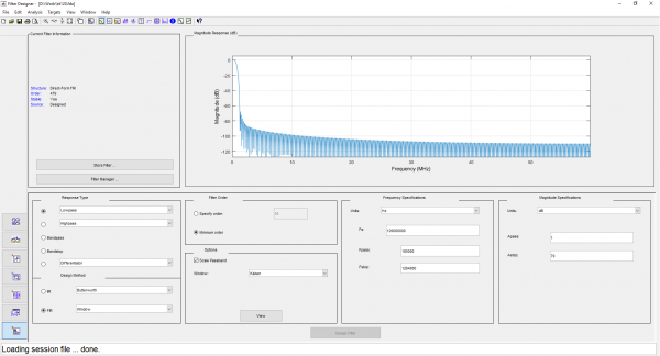
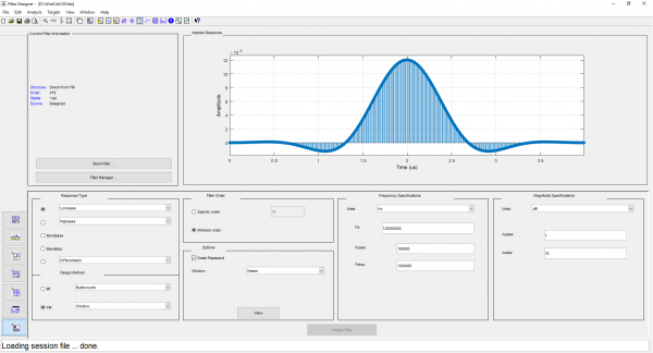
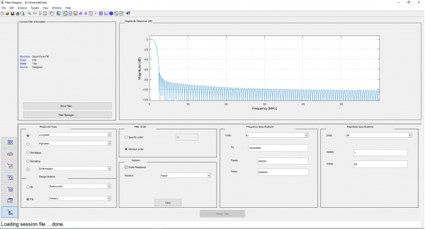
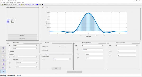
For the filters with a step of 1 MHz, we will select a low-pass filter bandwidth (half of the bandpass filter bandwidth) of 500 kHz, adjusting the impulse response length to 480 taps. For the filters with a step of 2 MHz, we will choose these parameters as 1 MHz and 240 taps, respectively. We select the Kaiser window. We will calculate the impulse response in filterDesigner and export it in C-header format:
Screenshots from filterDesigner
You can solve the problem directly: by constructing a corresponding array DDC (). This approach is good for FPGAs, where cost savings can be achieved by reducing the bit-width of the first stage processors. Additionally, FPGAs are the most energy-efficient way to implement this. However, the labor costs for this method are the highest.
When implementing filter banks on popular GPUs, it becomes possible to realize a more sophisticated algorithm: a polyphase filter bank based on FFT, which is available on CUDA from the library. In foreign literature, the algorithm is called Polyphase or WOLA (Weight, Overlap and Add) FFT Filterbank. My reluctance to draw prevents me from providing a clear explanation myself. There are many materials on the topic on the web, especially a clear graph is presented on page 11 (many thanks to the esteemed authors), here it is:
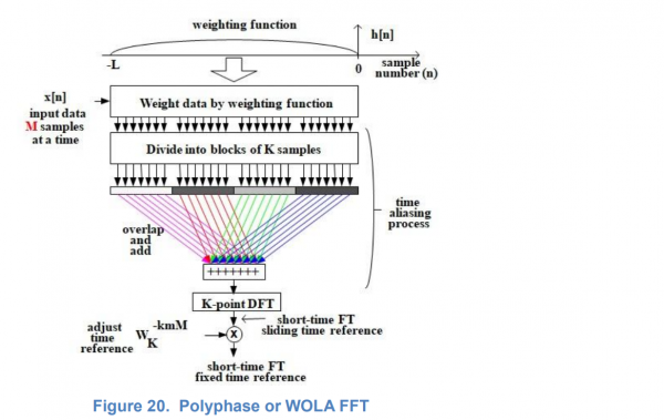
I will try to explain the processing scheme in my own words. Those with weak nerves are advised not to read.
I will try to explain the processing scheme in my own words within my methodological capabilities. FFT is the convolution of the input signal with the entire spectrum of complex orthogonal harmonics, which fit into the interval of the impulse response. The impulse response of the filter, to which the signal is multiplied before entering the FFT, is modulated by this spectrum of harmonics. In other words, the envelope of the impulse responses of the resulting comb filters is factored out. Then, the spectrum of harmonics is reduced by a certain factor due to the widening of the filter's passband relative to the filter in rectangular windowing. In the illustration, we see reduction by four. In other words, after widening the passband with a Kaiser window (simultaneously increasing the attenuation in the stopband), we only need one-fourth of the filters. The others are redundant; their frequency characteristics overlap. From the four consecutive FFT points, we choose only the zero point, the calculation of which is the summation of the four
input points taken over a time equal to one quarter of the duration of the original FFT.
We will select the hardware that is at hand. This is the input board from "Instrumental Systems" FMC126P. I have already written about it in one previous article. A submodule from the same company with an AD9371 transceiver and a bandwidth of 100 MHz is inserted into the FMC connector of the board. The entire stream from the transceiver can be continuously transmitted to the computer for processing.
Let’s choose a video card with a GTX 1050 GPU. (Just kidding, it chose us: it was all we had on hand, yanked from the computing unit for antenna calculations, but it was all the more surprising to see a working comb). Now, let’s move on to the software part.
Unfortunately, due to licensing issues, we cannot publish the complete code. We can only show the GPU kernels. However, the rest of the code isn't particularly interesting.
Here is the kernel that performs signal multiplication with a window and summation, along with a wrapper for its invocation:
__global__ void cuComplexMultiplyWindowKernel(const cuComplex *data, const float *window, size_t windowSize, cuComplex *result) {
    __shared__ cuComplex multiplicationResult[480];
    multiplicationResult[threadIdx.x] = cuComplexMultiplyFloat(data[threadIdx.x + windowSize / 4 * blockIdx.x], window[threadIdx.x]);
    __syncthreads();
    cuComplex sum;
    sum.x = sum.y = 0;
    if (threadIdx.x < windowSize / 4) {
        for(int i = 0; i < 4; i++) {
            sum = cuComplexAdd(sum, multiplicationResult[threadIdx.x + i * windowSize / 4]);
        }
        result[threadIdx.x + windowSize / 4 * blockIdx.x] = sum;
    }
}

cudaError_t cuComplexMultiplyWindow(const cuComplex *data, const float *window, size_t windowSize, cuComplex *result, size_t dataSize, cudaStream_t stream) {
    size_t windowStep = windowSize / 4;
    cuComplexMultiplyWindowKernel<<>>(data, window, windowSize, result);
    return cudaGetLastError();
}
The signal processing code that calls this kernel closely follows the algorithm scheme shown in the figure above, so I don’t see the point in including it here.
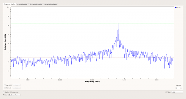
The combs were tested on the output spectrum of the channels in real time. A signal from a 2450 MHz signal generator was fed into the AD9371, and the filter selectivity matched the calculated values.
Plans include adapting the software to the XRTX board and implementing packet searching, if anyone finds it necessary or free time allows.
All the work on the software was done by , praise him!
Source: habr.com
