

We all know that the world of technology around us is digital or is striving towards that. Digital broadcasting is far from new; however, if you haven't specifically looked into it, the technologies associated with it might be unexpected for you.
Contents of the article series
- Part 4: Digital component of the signal
- Part 5: Coaxial distribution network
- Part 6: RF-signal amplifiers
- Part 7: Optical receivers
- Part 8: Optical backbone network
- Part 9: Headend
- Part 10: Troubleshooting in the CATV network
Components of the Digital Television Signal
A digital television signal represents a transport stream of various versions of MPEG (sometimes other codecs), transmitted via radio signals using quadrature amplitude modulation (QAM) of varying degrees. Anyone familiar with communications should understand these words clearly, so I'll just provide a GIF from , which I hope will help illustrate what this is for those who haven't yet shown interest:
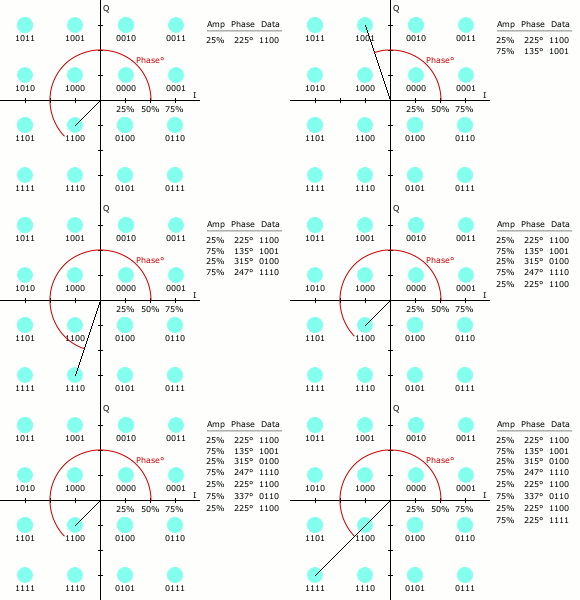
Such modulation, in one form or another, is used not only for 'tele-anachronism' but also for all data transmission systems that are at the forefront of technology. The speed of the digital stream in the 'antenna' cable reaches hundreds of megabits!
Parameters of the Digital Signal
Using the Deviser DS2400T device in the mode of displaying digital signal parameters, we can see what this looks like in reality:
Our network currently carries signals from three standards: DVB-T, DVB-T2, and DVB-C. Let's consider them one by one.
DVB-T
This standard did not become dominant in our country, giving way to the second version; however, it is quite suitable for use by operators because DVB-T2 receivers are backward compatible with the first-generation standard, meaning that subscribers can receive this signal on almost any digital television without additional set-top boxes. Furthermore, the standard designed for terrestrial transmission (the letter T stands for Terrestrial) has such good interference protection and redundancy that it sometimes works where for some reason the analog signal fails.
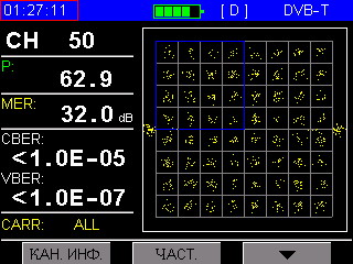
On the device screen, we can observe how the constellation of 64QAM is formed (the standard supports QPSK, 16QAM, 64QAM). It is clear that in real conditions, the points do not form a perfect shape but come with some dispersion. This is normal as long as the decoder can identify to which specific square the incoming point belongs, but even in the given image, areas can be seen where they are positioned at or close to the boundary. From this pattern, one can quickly assess signal quality visually: when the amplifier is not functioning properly, for instance, the points are scattered randomly, and the TV cannot compile a picture from the received data—it may exhibit pixelation or even freeze entirely. There are cases when the amplifier's processor 'forgets' to add one of the components (amplitude or phase) to the signal. In such cases, a circle or ring that occupies the entire field can be seen on the device screen. Two points outside the main field serve as references for the receiver and carry no information.
On the left side of the screen under the channel number, we see quantitative parameters:
Signal level (P) in the same dBmV as for the analog signal; however, for the digital signal, GOST regulates that it should only be 50 dBmV at the input to the receiver. This means that in areas with greater attenuation, 'digital' will perform better than analog.
The value of modulation errors (MER) indicates how distorted the signal we are receiving is, meaning how far the incoming point may be from the center of the square. This parameter is similar to the 'signal/noise' ratio in analog systems, with a normal value for 64QAM being from 28 dB. Here it is clearly visible that significant deviations in the provided image correspond to a quality above normal: this indicates the interference resistance of the digital signal.
The number of errors in the received signal (CBER)—the number of errors in the signal before being processed by any correction algorithms.
The number of errors after the Viterbi decoder (VBER) — the result of a decoder that uses redundant information to correct errors in the signal. Both of these parameters are measured in 'units per received amount'. For the device to show an error count of less than one in a hundred thousand or ten million (as shown in the image), it needs to receive those ten million bits, which takes some time on a single channel, so the measurement result does not appear immediately and may even initially show a poor reading (E-03, for example), but after a few seconds, it can report an excellent parameter.
DVB-T2
The standard for digital terrestrial broadcasting adopted in Russia can also be transmitted over cable. The constellation shape may be surprisingly unusual at first glance:

This rotation additionally enhances resistance to interference since the receiver knows that the constellation should be rotated at a specified angle, allowing it to filter what arrives without the prescribed shift. It can be observed that for this standard, the bit error rates are significantly higher, and errors in the signal before processing do not exceed the measurement limits, but represent a quite realistic 8.6 per million. A decoder is used to correct these errors. LDPC, hence the parameter is called LBER.
Due to enhanced resistance to interference, this standard supports a modulation level of 256QAM, but currently, only 64QAM is used in terrestrial broadcasting.
DVB-C
This standard was originally developed for transmission over cable (C — Cable) — a medium that is much more stable than air, hence allowing a higher degree of modulation than DVB-T, thus enabling the transmission of a larger volume of information without employing complex encoding.
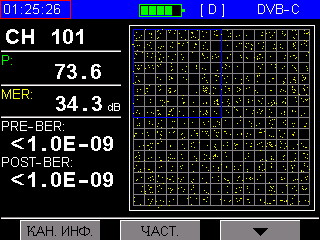
Here we see the 256QAM constellation. There are more squares, and their size has decreased. The probability of error has increased, meaning that a more reliable medium (or more complex encoding, as in DVB-T2) is required for transmitting such a signal. This signal may 'break apart' where analogue and DVB-T/T2 operate, but it also has a margin for error protection and error correction algorithms.
Due to the higher probability of error, the MER parameter for 256-QAM is normalized at 32dB.
The error bit counter has increased by another order of magnitude and now calculates one error bit per billion. However, even if there are hundreds of millions (PRE-BER ~E-07-8), the Reed-Solomon decoder used in this standard will correct all errors.
Source: habr.com
