

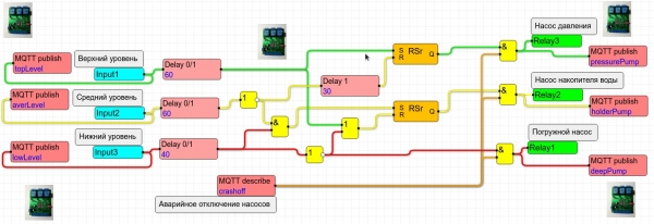
Main theses or what this article is about
The topic of the article is visual programming of PLCs ShIoTiny for smart homes, described here: .
In brief the concepts of nodes, connections, events, as well as the features of loading and executing a visual program on ESP8266, which serves as the basis for the PLC ShIoTiny.
Introduction or a couple of organizational questions
In the previous article regarding my development, I provided a brief overview of the controller’s capabilities ShIoTiny.
Strangely enough, the public showed considerable interest and asked me many questions. Some individuals even immediately suggested buying the controller from me. No, I am not against making some money, but my conscience does not allow me to sell a product that is still very raw software-wise.
Therefore, I posted the firmware binaries and device schematic on GitHub: .
Now anyone can flash the ESP-07 and play around with the firmware themselves. If someone really wants a board just like the one in the photo — I have a few available. Contact me at shiotiny@yandex.ru. But as the unforgettable Ogurtsov used to say: 'I take no responsibility for anything!'.
So, let’s get to the essence: what is a 'node' (node) and 'event'? How is the program executed?
As usual, we will start in order: with loading the program.
How the program is loaded
Let’s start with what happens when we press the button Upload in the editor ElDraw and our schematic-program, consisting of nice little squares, is sent to the device.
First, based on the diagram we drew, a text description is created.
Second, it is checked whether all the inputs of the nodes are connected to the outputs. There should be no 'hanging' inputs. If such an input is detected, the schematic in ShIoTiny will not load, and the editor will display the appropriate warning.
If everything goes successfully, the editor sends the text description of the schematic to ShIoTiny node by node. Naturally, the existing schematic in ShIoTiny is deleted beforehand. The received text description is saved in FLASH memory.
By the way, if you want to delete the schematic from the device, just upload an empty schematic (containing no node elements).
Once the entire program schema is loaded into the ShIoTiny PLC, it begins to "run." What does this mean?
It is important to note that the processes of loading the schema from FLASH memory when powered on and receiving the schema from the editor are identical.
First, the creation of node objects is carried out based on their description.
Then, the connections between the nodes are established. That is, links from outputs to inputs and from inputs to outputs are generated.
And only after all this is the main execution cycle of the program started.
I wrote for a long time, but the entire process — from loading the schema from FLASH memory to starting the main cycle — takes a fraction of a second for a schema of 60-80 nodes.
How does the main cycle work? Very simply. First, it waits for an event to occur events in any node, then processes this event. And so on endlessly, or until a new schema is loaded into ShIoTiny.
I have mentioned several times things like events, nodes and connections. But what is it from a programming perspective? We will discuss this today.
Nodes, connections, and events
A quick look at examples of program schemas shows that they consist of only two entities — nodes (or elements) and the connections between them. ShIoTinyNode
— is a virtual representation of some, data handler. This can be an arithmetic operation, a logical operation, or any operation that comes to mind. The main thing is that the node has an input and an output. or Input — is the place where the node receives data. The images of inputs are points that are always located on the left side of the node. actions. Output
— is the place from which the result of the node's operation is extracted. The images of outputs are points that are always located on the right side of the node. Some nodes do not have inputs. Such nodes generate results internally. For example, a constant node or a sensor node: they do not need data from other nodes to provide a result.
Other nodes, on the contrary, have no outputs. These are nodes that represent, for example, actuating devices (relays or similar). They receive data but do not generate results of computations available to other nodes. Additionally, there is a unique comment node. It does nothing and has no inputs or outputs. Its purpose is to serve as an explanation in the schema.
What is an event
...?
What is an "event"?
Eventevent»? Event — this is the occurrence of new data at any node. For example, events include: a change in the state of an input (node Input), receiving data from another device (nodes MQTT and UDP), the expiration of a given time interval (nodes Timer and Delay) and so on.
What are events needed for? To determine where new data has occurred at which node and which node states need to be changed due to the receipt of new data. An event 'passes' through the chain of nodes until it covers all nodes that need to be checked and changed.
All nodes can be divided into two categories.
Nodes that can generate events will be called 'active nodes».
Nodes that cannot generate events will be called 'passive nodes».
When a node generates an event (i.e., new data appears at its output), the state of the entire chain of nodes connected to the output of the event-generating node generally changes.
To make it clear, let's consider an example in the picture.
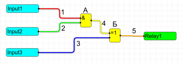
Active nodes here are Input1, Input2, and Input3. The other nodes are passive. Let's examine what happens when either input is closed. The results are conveniently summarized in a table.

As we can see, when an event occurs, a chain is built from the source node of the event to the endpoint node. The state of those nodes that do not fall within the chain remains unchanged.
A legitimate question arises: what happens when two or even several events occur simultaneously?
As a fan of Gleb Anfilov's creativity, I feel compelled to direct the curious inquirer to his book 'Escape from Surprises'. It serves as a 'theory of relativity for the smallest', where it is well explained what 'simultaneously' means and how to live with it.
But practically speaking, everything is much simpler: when two or even several events occur, all chains from each event source are built and processed consecutively in turn, with no wonders.
A logical question for a curious reader is: what happens if we connect the nodes in a ring? Or, as it is commonly said among these clever folks — introduce feedback. This means connecting the output of one node to the input of the previous node in such a way that the state of this node's output affects the state of its own input. You will not be allowed to directly connect the output of a node to its own input, as the editor will prevent that. ElDrawHowever, indirectly, as illustrated below — this can be done.
So, what will happen in this case? The answer is quite 'definite': it depends on what nodes you are using. Let's consider the example in the drawing.
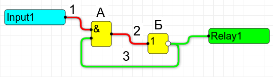
When the input contacts Input1 are open at the top input of node A — 0. At the output of node A, also 0. At the output of node B — 1. And finally, at the lower input of node A — 1. Everything is clear. If it's not clear to someone — see below for a description of how the 'AND' and 'NOT' nodes work.
Now we'll close the input contacts Input1, meaning we'll apply a one to the top input of node A. Those familiar with electronics know that we essentially have a classic generator circuit based on logic elements. Ideally, this circuit should continually output sequences of 1-0-1-0-1-0... and 0-1-0-1-0-1... The event should continually change the states of nodes A and B, cycling through 2-3-2-3…!
But in reality, this does not happen. The circuit falls into a random state — either the relay remains on or off, or it might buzz slightly as it toggles on and off several times in succession. Everything depends on the weather at the southern pole of Mars. And here’s why this occurs.
The event at node Input1 changes the state of node A, then node B, and so on in a loop several times. The program detects the 'looping' of the event and forcibly stops this carnival. After that, the state changes of nodes A and B are blocked until a new event occurs. The moment when the program decides — 'enough spinning in circles!' — generally depends on many factors and can be considered random.
Be careful when connecting nodes in a ring — the effects will not always be obvious! Be well aware of what you are doing and why!
Can we still build a generator on the available nodes? Yes, we can! However, this requires a node that can generate events by itself. And such a node exists — it’s the "delay line." Let’s see how a generator works with a period of 6 seconds in the illustration below.
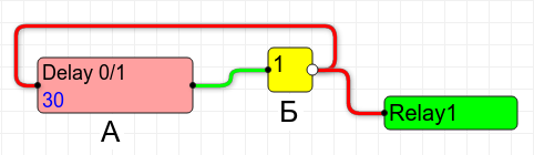
The key element of the generator is node A — the delay line. If the state of the input to the delay line changes from 0 to 1, then 1 will not appear on the output immediately, but only after a specified time. In our case, that is 3 seconds. Similarly, if the state of the input to the delay line changes from 1 to 0, then 0 will appear on the output after the same 3 seconds. The delay time is specified in tenths of a second. So, a value of 30 means — 3 seconds.
A feature of the delay line is that it generates an event after the delay time has elapsed.
Let’s assume that initially, the output of the delay line was 0. After passing through node B — the inverter — this 0 changes to 1 and enters the input of the delay line. Nothing happens immediately. The output of the delay line remains 0, but the timer for the delay starts. Three seconds pass. And then the delay line generates an event. A 1 appears at the output. This 1 then passes through node B — the inverter — turns into 0, and enters the input of the delay line. Another 3 seconds pass… and the process repeats. Thus, every 3 seconds, the state of the output of the delay line changes from 0 to 1 and then from 1 to 0. The relay clicks. The generator works. The pulse period is 6 seconds (3 seconds on a 0 output and 3 seconds — 1).
However, in real circuits, this example is usually unnecessary. There are special timer nodes that perfectly generate a sequence of pulses with a specified period without external help. The duration of the “0” and “1” in these pulses equals half the period.
To set periodic actions, use timer nodes.
I would like to note that such digital signals, where the duration of "0" and "1" are equal, are called "meander."
I hope I've clarified a bit about how events propagate between nodes and what not to do.
Conclusion and references
The article turned out to be short, but it is a response to the questions that arose regarding nodes and events.
As firmware evolves and new examples emerge, I will write about programming ShIoTiny brief articles as long as they interest people.
As before, the scheme, firmware, examples, node descriptions, and everything .
Questions, suggestions, criticism — send them here: shiotiny@yandex.ru
Source: habr.com
