


Main theses or what this article is about
We continue the series of articles on ShIoTiny — a visually programmable controller based on a chip ESP8266.
This article explains, using the example of a project for controlling ventilation in a bathroom or another room with high humidity, how to build a program for ShIoTiny.
The previous articles in the series.
Links
Introduction
Understanding comes from experience. This is a truth proven by time and generations. Thus, there is nothing better for learning practical skills than trying to do something on your own. Examples that illustrate what can be done and what should be avoided will come in handy here. Others' mistakes may not prevent your own failures, but they can help reduce their number.
Questions and letters from readers of previous articles prompted me to create a small example project for controlling ventilation to demonstrate how ShIoTiny nodes work.
The original idea upon which the controller was based ShIoTiny — a pump-irrigation station — won't suit everyone and may not be of interest. Therefore, I chose a universally understood and useful ventilation control system as an example.
I should mention that the project idea is not mine; I and then adapted it to ShIoTiny.
First, understand what you want
The process of improvement is infinite. This characteristic has led to the downfall of many good ideas and projects. Instead of releasing something that, while not perfect, is functional, developers often continue perfecting it. They refine it until their competitors surpass them by launching something that, albeit imperfect (and often downright shabby), works.
Therefore, it is crucial to know where to draw the line in a project. In other words, we need to determine what we want to achieve at the end of the project based on what we have at the beginning. In Russian, there is a wonderful concise term 'plan' for a document created specifically to describe the process of creating something, which lazy translators and deficient managers have recently bizarrely started calling a 'roadmap.' But let that be.
Our plan will be as follows. Let's assume there is a room where the humidity can sometimes rise significantly, such as a bathroom or kitchen. Humidity is unpleasant, and the time-honored way to combat it is to ventilate the space. There are many methods of ventilation. However, we'll skip over exotic and outdated methods such as fans operated by people and focus on a regular fan. Fans are cheaper and easier to find in our area.
In short, we want to control the fan: turn it on and, accordingly, turn it off. More precisely, we want it to turn on and off automatically as needed.
Now we need to determine the conditions under which the fan should turn on and the conditions under which it should turn off.
This is quite obvious: if the humidity exceeds a certain threshold, the fan turns on and exhausts the air; if the humidity normalizes, the fan turns off.
An observant reader will immediately latch onto the word "threshold." Set by whom? How is it set?
The threshold humidity can be set in several ways. We will consider two of them: the first — using a variable resistor, and the second — via the network using the MQTT protocol. Each of these methods has its advantages and disadvantages, which will be discussed later.
For those who didn't understand, let me clarify that "threshold humidity" is the level of humidity at which the fan must be turned on.
The next question is whether to give the user the right to turn on the fan directly. That is, regardless of the humidity level, at the push of a button? We will provide such an option. After all, the fan may be needed not only when the humidity is high but also to eliminate, for example, unpleasant odors, commonly referred to as "stench."
So, we understand what we want and even a bit about how it will work. Let's briefly list all the functions of our ventilation control system:
- setting the threshold humidity level (two options);
- measuring the humidity level;
- automatic fan activation;
- automatic fan deactivation;
- manual fan activation (at the push of a button).
So, the plan is clear. We need to implement all the functions listed above in our program. We will act based on this 'plan.' First, let’s draw the structural diagram of the device.
Structural diagram of the device
In general, we will have two such diagrams. The first one is for the case where the threshold humidity level is set by a variable resistor. The second diagram is for the case where the threshold humidity level is set over the network using the MQTT protocol.
However, since these diagrams will differ by only one element—the variable resistor for setting the threshold humidity level—we will draw only one structural diagram. Of course, the structural diagram according to GOST looks different. But we are not targeting experienced engineers; we are focusing on the younger generation. Therefore, clarity is more important.
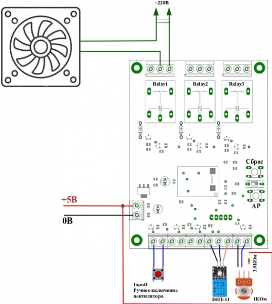
So, what do we see in the picture? A fan connected to a relay Relay1 of the controller. I would like to point out that the fan is a device operating under high voltage. So, if someone is going to build this themselves—exercise caution. That is, at a minimum, before inserting your fingers or measuring devices into the circuit—cut off the power to the fan. And a second note. If your fan is more powerful than ShIoTiny250W , then it should not be connected directly to— only through a starter. ShIoTiny We are clear on the fan. Now the button for 'manual fan activation.' It is connected to the input
Input1 . There's really nothing more to explain here.Temperature and humidity sensor
DHT-11 DHT-22 (or or their equivalents). A special input on the controller is provided for its connection. As can be seen in the picture, connecting such a sensor is not a problem. And finally, the variable resistor setting the threshold humidity level. More precisely, it is a divider consisting of a variable resistor and a constant resistor. There are no issues with its connection, but I would like to clarify that the built-in ADC on ShIoTinyis designed for a maximum of 1 Volt. Hence, a voltage divider of about 5 times is needed.
And I remind you once again that this divider is not necessary if the threshold humidity level is set over the network using the MQTT protocol. ESP8266 is rated for a maximum of 1 Volt. Hence, a voltage divider of about 5 times is required.
And once again, I remind you that this divider is unnecessary if the threshold humidity level is set via the network using the MQTT protocol.
Let's start by creating the device operation algorithm in the ElDraw ShIoTiny editor. You can read how to access this editor in previous articles or in the guide, the link to which is at the beginning of this article.
First option, the simplest
Let's start with the basics: turning on the relay Relay1 when the threshold humidity level is exceeded for a specified time.
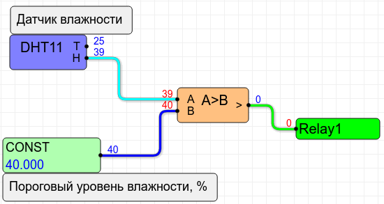
As we can see, nothing complicated: just four nodes, not counting the comment nodes. DHT11 — this is the temperature and humidity sensor itself (you can change it to DHT22).
Constant CONST — the threshold humidity level, in percent.
The comparator is a node that compares two numbers and outputs 1 if the specified condition is met and 0 if it is not.
In our case, this condition will be A>B, where A — the humidity level measured by the sensor, and B — the threshold humidity level.
As soon as the measured humidity level (A) exceeds the threshold humidity level (B), the comparator will output 1 and the relay will turn on. Conversely, as soon as the humidity level normalizes (i.e., A>B A<=B ), it will output 0 and the relay will turn off.), the comparator will output 1 and the relay will turn on. Conversely, as soon as the humidity level normalizes (i.e., A>B Is everything clear? If not, please read it again or check the description of how the nodes work in the guide.
I should note that the data from the sensor
updates approximately once every 10 seconds. Therefore, the relay cannot turn on and off more frequently than once every 10 seconds. DHT11 Everything would be fine, but we would like to set the threshold humidity level using a variable resistor. It's quite simple!
We will just replace the constant node with an ADC node. After all, it's to the ADC that we connected the voltage divider with the variable resistor.
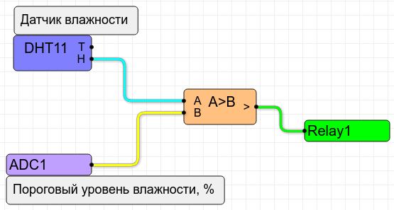
The voltage at the ADC input varies from 0 to 1 Volt. Meanwhile, the humidity at the sensor output ranges from 0 to 100%. How do we compare them? It's easy. The ADC node in
not only measures the voltage at the input but can also ShIoTiny scale and shift the values..
That is, at the output of the ADC1 node (ADC), the value will be Xcalculated according to the formula

, where  — the voltage at the ADC input (from 0 to 1V); k — the range (ADC range), and b— the offset (ADC offset). Therefore, if we set k=100 and b=0, then as
  varies from 0 to 1, the output value X of the ADC node will change in the range from 0 to 100. That is, it will be numerically equal to the variation range of humidity from 0 to 100%.
Alternatively, by simply turning the variable resistor motor, you can set the threshold humidity level from 0 to 100. The only inconvenience is that there are no display devices. However, in practice, if you make 6 divisions on the variable resistor at 0%, 20%, 40%, 60%, 80%, and 100%, this is sufficient to set the threshold humidity level.
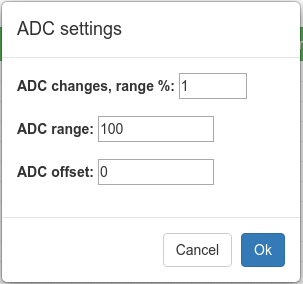
How do we set the coefficients? k — the range (ADC range), and b- Offset (ADC offset)? It's as easy as pie! Just click with your mouse pointer on the node ADC1 and a settings window will appear immediately. In this window, you can set everything you need. For our case, it will look like the one shown in the picture.
So, we have a basic working solution. Let's start improving it.
By the way, the simplest solution has one advantage — it doesn't need the internet. It is completely autonomous.
The second option is to connect a button.
Everything works and everyone is happy. But there is a problem, we cannot turn on the ventilation manually. We have already agreed that . There's really nothing more to explain here. there will be a button connected to the input that will turn the fan on and off regardless of the humidity sensor.
It's time to process this button in our scheme-program.
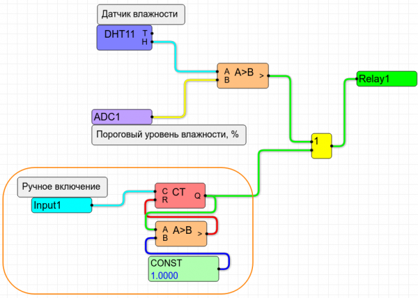
The block processing the button press is highlighted with an orange line. It consists of a button press counter that resets to zero when its output value exceeds one (green line, output of the node CT).
Everything operates as simply as before: the counter CT counts the button presses connected to the input. . There's really nothing more to explain here.That is, the value at the output of this counter increases by 1 with each press of the button.
As soon as this value reaches two (that is, greater than 1), a 1 will appear at the comparator's output A>B and this 1 will reset the counter CT to zero. I mean the lower comparator in the scheme!
Thus, our button has two states — 0 and 1. If we needed more states (3 or 4 or even more), we would just change the constant CONST from one to another value.
So, we have two conditions for turning on the fan: exceeding the set humidity level and a single press of the button. The fan will turn on if either condition is met. It will operate until the button is pressed again I can use or the humidity level returns to normal.
Of course, we could complicate the algorithm even more, but we won't do that—let's leave room for creativity for those who wish.
Third option, we connect to the internet.
Everything we've described is quite functional. But what about style? Any pimple-faced hipster-hacker-cracker will laugh at someone who turns a knob and presses a button instead of controlling it from a smartphone! Turning a knob is 'not trendy'. But sliding a finger across a smartphone screen, rubbing that finger raw—that's the pinnacle of a hipster-hacker-cracker's desires (I could never distinguish all of them, so if I'm mistaken, I apologize).
But let's be lenient towards these individuals. Internet-based control has its real advantages. First, there's visibility. There are plenty of applications across all platforms that allow a few taps to create a panel for our controller-Carlson that is quite usable. Second, it provides the ability to remotely monitor humidity levels in a room. And third, you can not only see if the fan is spinning but also what the set humidity threshold is. Additionally, you can tell whether the fan turned on automatically or manually. In general, it's everything you could wish for.
Surely, it's a bit much for a fan to receive such attention. But it's just an example.
So, to connect to the internet, we will use the technology MQTT and the corresponding protocol.
To use this technology, we need a MQTT broker. This is a special server that services MQTT clients, for example, ShIoTIny and your smartphone.
The essence of the technology MQTT is that any client publishes arbitrary data to the MQTT broker (server) under a specific name (called topic in the terminology MQTT). Other clients can subscribe to arbitrary data by name (topic) and receive newly published data. In other words, all data exchange happens on a client-broker-client basis.
I I won't dwell on the details. There are plenty of articles and tutorials online about how MQTT works and what programs are available for creating control panels. I'll simply show how to receive and publish data using ShIoTiny.
As a broker, I used , but the principle is the same everywhere.
So, let's assume you've registered on the MQTT broker.In general, the broker will provide you with (or require you to create) a username and password (for authentication), as well as a connection port. Connect ShIoTiny to to the MQTT broker using two methods — regular connection and by TLS (SSL).
All these parameters are entered on the ShIoTiny tab, section NetworkingMQTT Connection to server If your.
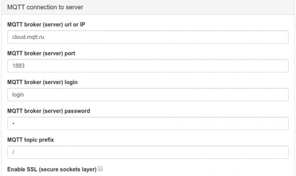
does not require authentication — leave the username and password fields empty. MQTT broker MQTT topic prefix
Parameter needs a separate explanation. The MQTT parameters prefix is a string added to the topic name (
) when publishing and subscribing to the MQTT broker. To set thetopicMQTT prefix for your controller, simply enter it in the field labeled “ MQTT Topic Prefix”). The prefix always starts with a slash (» («needs a separate explanation.)! If you do not enter a slash in the input field, it will be added automatically. The prefix cannot contain the character«/». There are no other restrictions. «#» and «+»For example, if you are publishing the parameter “
” (or subscribing to it), and your prefix is set to “status”, then on the broker this parameter will be published under the name “/shiotiny/. If you have an empty prefix set, all parameters on the broker will start with a slash (/shiotiny/statuswill be published as “«/»): «statusSo, let's assume you registered on/status».
and received a username, password, and port. Then you entered these parameters on the tab MQTT broker. Assuming the prefix is set to “ NetworkingMQTT Connection to server If your of the controller. I would like to point out that the fan is a device operating under high voltage. So, if someone is going to build this themselves—exercise caution. That is, at a minimum, before inserting your fingers or measuring devices into the circuit—cut off the power to the fan. And a second note. If your fan is more powerful than ShIoTiny.
Let's start by publishing the state of all key parameters: relay/room/».
Relay1 , manual on state, automatic on state, and finally the threshold and current humidity levels. And as a bonus — the temperature in the room. To see how this is done, refer to the illustration.As we can see, the difference from the previous version is only the nodes “
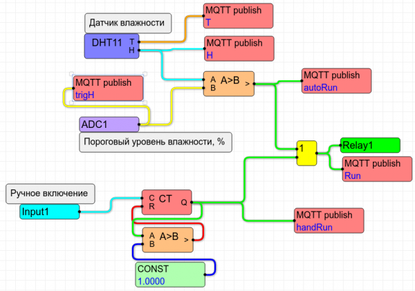
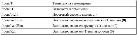
MQTT Publish”. Taking into account the prefix, the following parameters will be published:As we can see, the entire system state is at our fingertips!
But we want to not only see but also control. What to do? Very simple. We will forgo setting the humidity threshold using
ADC and a variable resistor, and we will set this very threshold directly from our smartphone! We remove the ADC node from the schematic and include three new nodes: MQTT FLASH store
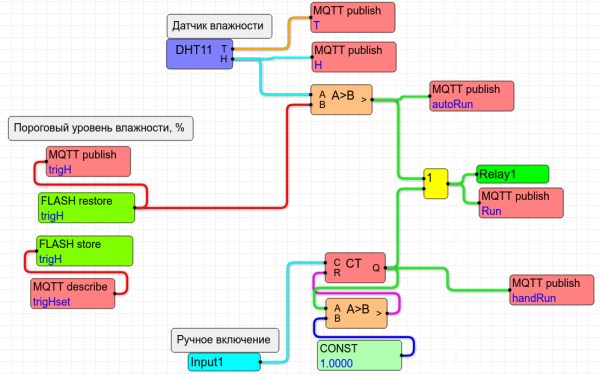
FLASH restore MQTT describe, The node's function is and clear: it receives the parameter.
(humidity threshold level) from the clear: it receives the parameter MQTT broker. But what does it do with the data next? It simply passes them to the node /room/trigHset . . But what does it do with the data next? It simply forwards it to the node. MQTT describe, which, in turn, saves this data in non-volatile memory under the name trigH. After that, the node The node's function is reads data from non-volatile memory under the name trigH and what happens next we already know.
Why such complications? Why not simply pass the received data to the comparator?
As my friend S. Holmes used to say — it's elementary! No one guarantees that after turning on your device, it will connect to to the MQTT broker. And humidity needs to be measured. And the fan needs to be turned on. But without information about the humidity threshold level, this is impossible! Therefore, our device, upon startup, retrieves the previously saved humidity threshold level from non-volatile memory and uses it for decision-making. And when a connection is established with the MQTT broker and someone publishes a new value /room/trigHset, then this new value will be used.
From there, you can come up with anything. For example, in addition to humidity, introduce temperature monitoring. Or add 'smart' lighting control (we still have two relays and two inputs left unused). Everything is in your hands!
Conclusion
Thus, we have examined several examples of implementing a simpler controller based on ShIoTiny. Perhaps this will be useful to someone.
As always, suggestions, wishes, questions, typos, and more — send to: shiotiny@yandex.ru
Source: habr.com
