

Creating a gateway between Wi-Fi and LoRa for UDP
I had a childhood dream — to give every household 'non-Wi-Fi' device a ticket to the network, that is, an IP address and a port. After some time, I realized that I shouldn't delay. I need to take action.
Technical specifications
Make an M5Stack gateway with an installed LoRa Module (Figure 1). The gateway will connect to the Wi-Fi network, obtaining a local IP address via DHCP. At regular intervals, the gateway will broadcast its name (analogous to SSID for Wi-Fi) and the range of allowed ports, so that other devices know there is such a network to connect to and what range they can choose a free port from. Since this will be a prototype, authentication is not necessary this time. New client devices will find the available LoRa network and transmit the chosen port to it. After the gateway receives the port from the new client, it checks if it is free; if yes, it registers the new client and starts listening on this port on its own asynchronous UDP server. After registration, the client will receive either approval or denial for the use of the declared port. The operating procedure is displayed in Table 1.
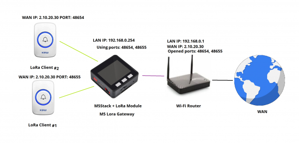
Figure 1
Table 1
Side
Direction and data
Side
Session
[ client ]
<— signal beacon —
[ gateway ]
0xA1
[ client ]
— chosen port —>
[ gateway ]
0xB1
[ client ]
<— approval or denial —
[ gateway ]
0xA2
[ client ]
— UDP packet —>
[ gateway ]
0xB2
[ client ]
<— UDP packet —
[ gateway ]
0xA3
[ network ]
<— UDP packet —
[ gateway ]
0xC1
Various Modules for M5Stack are lying on my desk, looking bored. Let's take the LoRa module and have some fun with it. The concept of the modules is excellent! What can I say? However, I have the first revision of the modules, which have an awful built-in antenna made on a flexible PCB and glued to the side wall of the case. I once conducted field tests of such modules (you can check them out on a Russian-language channel on YouTube):

Naturally, I had to remove these remnants and solder in standard helical antennas that come with the Ra-01. After such customization, the communication range improved significantly, but there was a side effect — the antenna has a diameter greater than the permissible distance between the modules. I had to abandon the Final module for the duration of the project.
The first difficulties from synchronization rigidity
It would seem, just take the library WiFiUdp.h, where everything is available for the comfortable existence of a UDP server, it is not. The library is designed to set up a synchronous server, which, unfortunately, cannot handle multiple connections simultaneously within a single thread. Such a library is not suitable for the current task. I had to drink many cups of tea and look for a library that would allow me to set up an asynchronous UDP server capable of supporting multiple connections at once. Such a library was found — AsyncUDP.h. What is the difference between a synchronous server and an asynchronous one? Let’s look at six episodes in Figure 2, which trivially display the working options of sockets.
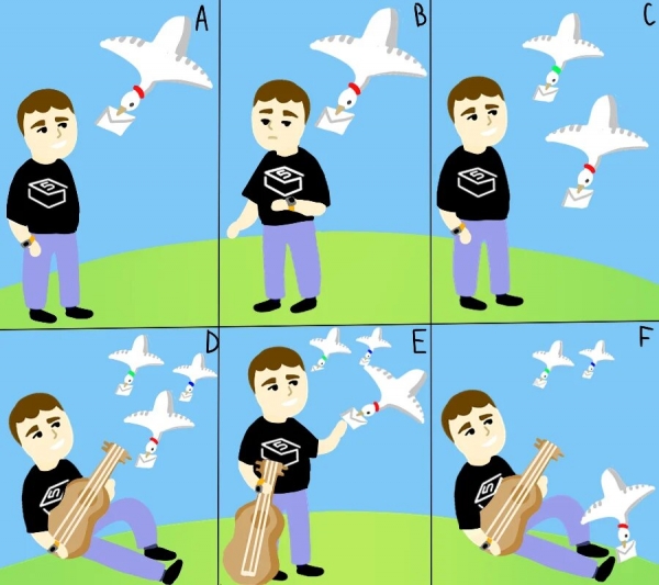
Figure 2
Starring:
Person in the role of Socket;
Dove in the role of Connection;
Letter in the role of Data.
Episode A. Synchronous socket without timeout
The person will stand until the dove brings him the letter.
Episode B. Synchronous socket with timeout
The person waits for the agreed time with the dove, and if it does not arrive on time, the person will leave.
Episode C. Synchronous socket with multithreading
The person is idly watching how the doves deliver the letters by themselves.
Episode D. Asynchronous socket (when there is nothing to receive yet)
The person is engaged in their favorite activities but doesn’t forget about the doves.
Episode E. Asynchronous socket (when there is something to receive)
The person briefly distracted from their activities to receive a letter from the dove.
Episode F. Asynchronous socket with multithreading
The person is engaged in their activities and is watching how the doves deliver the letters by themselves.
If you were attentive, you must have noticed that the collars on the doves in each episode have a specific color. And this is not coincidental. In episodes A and B, only one socket is working on the server, that’s all. In episode C, two sockets are already working. In episodes D, E, and F, there are three sockets each. "Why are there two there and three here?" you may ask. These are conditionally 2 and 3; in reality, instead of 2, there could be 20, and instead of three, 200. The task is to show that asynchronous sockets do not strain the hardware as much as synchronous ones.
How much can fit where?
Let’s look at Table 1, which presents the structure of a UDP packet and consider what can be done with it.
Table 1. Structure of UDP Packet
Bits
0 — 15
16 — 31
0-31
Source port
Destination port
32-63
Length
Checksum
64-…
Data
Let's add one more field at the very beginning of this table. Session (1 Byte). This is enough for this project. Based on the session, the device will know what to do with the packet next. Now let's come up with codes for the sessions and record them in table 2.
Table 2. Explanation of Sessions
Code
Title
Explanation
0xA1
Beacon
The gateway broadcasts the name of the LoRa network and the range of allowable ports at a specified interval. This is necessary for new clients to see the available network and for current clients to determine the signal level when no transmissions are occurring.
0xB1
Request
When a client detects the network, it sends the preferred port.
0xA2
Acceptance or Rejection
If the port requested by the client is free, then the server responds with acceptance; otherwise, it responds with rejection.
0xB2
Up-link
When the client sends a UDP packet to the gateway.
0xA3
Down-link
When the gateway sends a UDP packet to the client.
0xC1
Continuation of Up-link
When the gateway sends a UDP packet into the local network.
Alright. Now let's discuss the composition of sessions in table 3.
Table 3. Sessions
Session Name
Composition
Beacon
Session Code (1 Byte) + LoRa Network Name (4 Bytes) + Starting Port (2 Bytes) + Ending Port (2 Bytes)
Request
Transmission Code (1 Byte) + LoRa Network Name (4 Bytes) + Preferred Port (2 Bytes)
Acceptance or Rejection
Transmission Code (1 Byte) + LoRa Network Name (4 Bytes) + Preferred Port (2 Bytes) + Result (1 Byte)
Up-link
Transmission Code (1 Byte) + LoRa Network Name (4 Bytes) + Remote IP Address (4 Bytes) + Remote Port (2 Bytes) + Local IP Address (4 Bytes) + Local Port (2 Bytes) + Data Size (2 Bytes) + Data
Down-link
Transmission Code (1 Byte) + LoRa Network Name (4 Bytes) + Remote IP Address (4 Bytes) + Remote Port (2 Bytes) + Local IP Address (4 Bytes) + Local Port (2 Bytes) + Data Size (2 Bytes) + Data
Continuation of Up-link
Remote IP Address (4 Bytes) + Remote Port (2 Bytes) + Data Size (2 Bytes) + Data
I wrote two clients for Arduino and M5Stack. You can see how it works at There are no issues within the apartment; I haven't conducted field tests yet.
The source code is available on GitHub at
You can learn more about the M5Stack Base device and purchase it
You can select wireless LoRa modules for the Base device
I would be happy if this project proves useful to you. Thank you very much for your time!
List of literature and (or) sources:
Source: habr.com
