

Today we will begin studying routers. If you completed my video course from the first to the 17th lesson, you have already learned the basics of switches. Now we are moving on to the next device – the router. As you know from the previous video lesson, one of the topics of the CCNA course is titled – Cisco Switching & Routing.
In this series, we won't focus on Cisco routers, but rather consider the concept of routing in general. We will cover three topics. First, an overview of what you already know about routers and a discussion of how this knowledge can be applied alongside what you learned about switches. We need to understand how switches and routers work together.
Next, we will explore what routing is, what it means, and how it works, after which we will move on to types of routing protocols. Today I will use the topology you have seen in previous lessons.
We looked at how data moves across a network and how the three-way TCP handshake occurs. The first message sent over the network is the SYN packet. Let's examine how the three-way handshake takes place when a computer with the IP address 10.1.1.10 wants to connect to a server at 30.1.1.10, essentially trying to establish an FTP connection.
To initiate the connection, the computer creates a source port with a random number, 25113. If you've forgotten how this works, I recommend reviewing the previous video lessons that covered this topic.
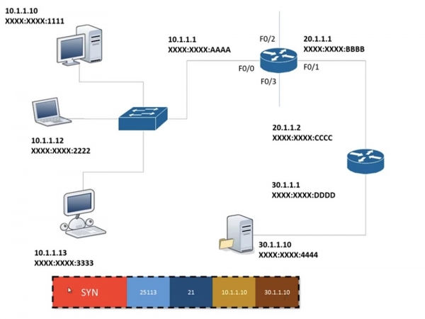
Next, it places the destination port number in the frame, knowing it needs to connect to port 21, and then adds the third layer OSI information, which includes its own IP address and the destination IP address. The data marked with a dotted line does not change until it reaches the endpoint. Upon reaching the server, it also remains unchanged, but the server adds second-layer information to the frame, specifically the MAC address. This is because switches only recognize second-layer OSI information. In this scenario, the router is the only network device that considers third-layer information; naturally, the computer also works with this information. So, the switch deals only with second-layer information, while the router handles third-layer.
The switch knows the source MAC address XXXX:XXXX:1111 and wants to find out the MAC address of the server that the computer is trying to reach. It compares the source IP address with the destination address, realizes that these devices are located in different subnets, and decides to use the gateway to access the other subnet.
I often get asked who decides what the gateway IP address should be. Firstly, this is determined by the network administrator who creates the network and assigns an IP address to each device. As an administrator, you can assign any address to the router that falls within the range of allowed addresses for your subnet. Typically, it's the first or last valid address, but there are no strict rules about its assignment. In our case, the administrator assigned the gateway, or router, the address 10.1.1.1 and assigned it to port F0/0.
When you configure a network on a computer with a static IP address of 10.1.1.10, you assign a subnet mask of 255.255.255.0 and a default gateway of 10.1.1.1. If you are not using a static address, then the computer uses DHCP, which assigns a dynamic address. Regardless of whether the computer uses a static or dynamic IP address, there must be a gateway address to access another network.
Thus, the computer 10.1.1.10 knows it must send a frame to the router at 10.1.1.1. This transmission occurs within the local network, where the IP address is irrelevant; only the MAC address matters. Assume that the computer has never communicated with the router before and does not know its MAC address, so it must first send an ARP request that asks all devices in the subnet: 'Hey, who has the address 10.1.1.1? Please tell me your MAC address!' Since ARP is a broadcast message, it is sent to all ports on all devices, including the router.
The computer 10.1.1.12, upon receiving the ARP, thinks: "No, my address is not 10.1.1.1," and discards the request. The same happens with the computer 10.1.1.13. The router, upon receiving the request, understands that it is being queried and sends the MAC address of port F0/0 – as all ports have different MAC addresses – to computer 10.1.1.10. Now, knowing the gateway address XXXX:AAAA, which is the destination address in this case, the computer adds it to the end of the frame addressed to the server. Along with this, it sets the FCS/CRC frame header, which represents an error-checking mechanism for transmission.
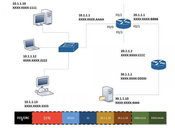
After that, the frame from computer 10.1.1.10 is sent over to the router 10.1.1.1. Upon receiving the frame, the router removes the FCS/CRC using the same algorithm for checking as the computer does. The data consists of nothing more than a series of zeros and ones. If the data is corrupted, meaning a 1 becomes a 0 or a 0 becomes a 1, or if there is data leakage, which often occurs when using a hub, then the device must resend the frame.
If the FCS/CRC check is successful, the router looks at the source and destination MAC addresses and removes them since this information is layer 2, and moves to the frame body, which contains layer 3 information. From it, it learns that the information contained in the frame is intended for the device with IP address 30.1.1.10.
The router somehow knows where this device is located. We didn't discuss this when looking at how switches work, so let's address it now. The router has 4 ports, so I added some connections to it. So, how does the router know that the data for the device with IP address 30.1.1.10 should be sent through port F0/1? Why doesn't it send it through port F0/3 or F0/2?
The fact is that the router operates with a routing table. Each router has such a table that allows it to decide through which port to forward a specific frame.
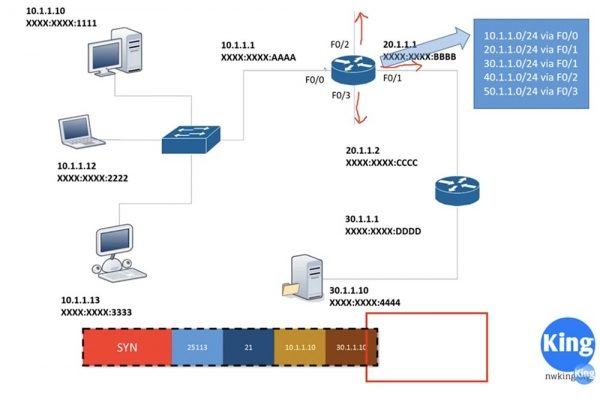
In this case, port F0/0 is configured with the IP address 10.1.1.1, indicating that it is connected to the network 10.1.1.0/24. Similarly, port F0/1 is configured with the address 20.1.1.1, meaning it is connected to the network 20.1.1.0/24. The router is aware of both networks because they are directly connected to its ports. Thus, it inherently knows that traffic for the network 10.1.1.0/24 should go through port F0/0, while traffic for 20.1.1.0/24 should go through port F0/1. So, how does the router determine which ports to use for additional networks?
We observe that the network 40.1.1.0/24 is connected to port F0/2, network 50.1.1.0/24 to port F0/3, and network 30.1.1.0/24 links the second router to the server. The second router also has a routing table indicating that network 30. is connected to its port, which we will label as 0/1, while it is connected to the first router via port 0/0. This router knows that its port 0/0 connects to network 20., and port 0/1 connects to network 30., but it does not have any further information.
Similarly, the first router is aware of networks 40. and 50. connected to ports 0/2 and 0/3, but it has no knowledge about network 30. The routing protocol provides routers with information that they do not possess by default. The mechanism by which these routers interact with each other is the foundation of routing, which can involve both dynamic and static routing.
Static routing means that the first router is provided with information: if communication with network 30.1.1.0/24 is necessary, it should use port F0/1. However, when the second router receives traffic from the server intended for computer 10.1.1.10, it does not know what to do with it, as its routing table only contains information about networks 30. and 20. Therefore, static routing must also be configured on this router: if it receives traffic for network 10., it should send it through port 0/0.
The issue with static routing is that I must manually configure the first router to work with network 30., and the second router to work with network 10. This is straightforward if I have only 2 routers, but when I have 10 routers, setting up static routing becomes very time-consuming. In such cases, it makes sense to use dynamic routing.
Thus, upon receiving a frame from the computer, the first router checks its routing table and decides to send it through port F0/1. In doing so, it adds the source MAC address XXXX.BBBB and the destination MAC address XXXX.CCCC to the frame.
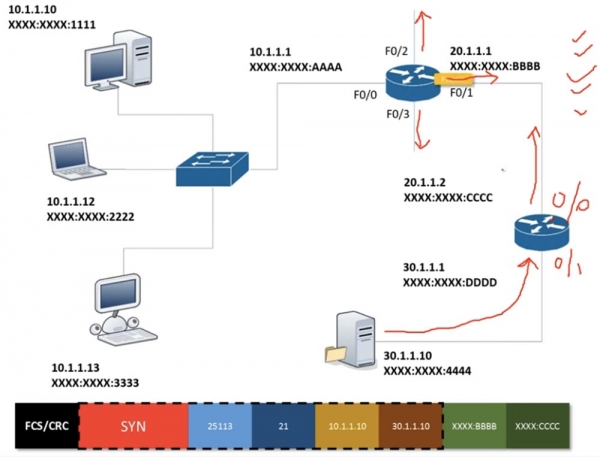
Upon receiving this frame, the second router 'trims' the MAC addresses associated with the second layer of the OSI model and proceeds to the information at the third level. It sees that the destination IP address 30.1.1.10 belongs to the same network as port 0/1 of the router, adds the source MAC address and the destination device's MAC address to the frame, and sends the frame to the server.
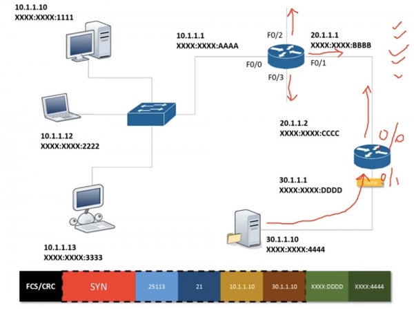
As I mentioned earlier, a similar process is repeated in the reverse direction, meaning the second stage of the handshake occurs, during which the server sends back a SYN ACK message. Before that, it discards all unnecessary information and keeps only the SYN packet.

Upon receiving this packet, the second router processes the received information, supplements it, and forwards it.
So, in previous lessons, we studied how switches work, and now we have learned how routers operate. Let's answer the question of what routing represents in a global sense. Suppose you come across a road sign at a roundabout. You see that the first exit leads to the Royal Air Force Base Fairfax, the second to the airport, and the third goes south. If you choose the fourth exit, you'll end up in a cul-de-sac, while the fifth takes you through the city center to Brecksby Castle.
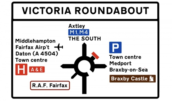
In general, routing is what causes a router to make decisions about where to direct traffic. In this case, you, as a driver, have to decide which exit to take at the roundabout. In networks, routers have to make decisions about where to send packets or frames. You must understand that routing enables the creation of tables upon which routers base these decisions.
As I said, there is static and dynamic routing. Let's consider static routing, for which I will draw 3 devices connected to each other, with the first and third devices linked to networks. Suppose one network 10.1.1.0 wants to connect with the network 40.1.1.0, while between the routers there are networks 20.1.1.0 and 30.1.1.0.
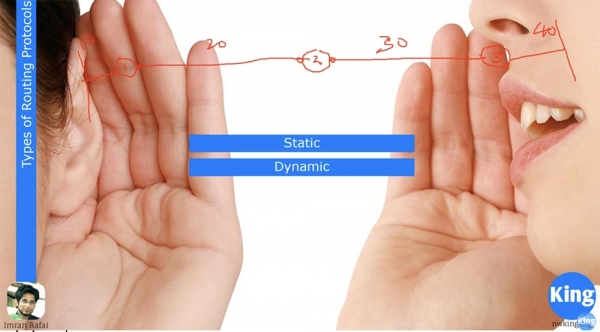
In this case, the router ports must belong to different subnets. Router 1 by default knows only about networks 10. and 20., and nothing about the other networks. Router 2 knows only about networks 20. and 30., as they are connected to it, while Router 3 knows only about networks 30. and 40. If network 10. wants to communicate with network 40., I must inform Router 1 about network 30. and that if it needs to forward a frame to network 40., it should use the interface for network 20. and send the frame over that same network 20.
I need to assign two routes to the second router: if it wants to send a packet from network 40. to network 10., it should use the port for network 20., and for sending a packet from network 10. to network 40. – the port for network 30. Similarly, I need to provide Router 3 with information about networks 10. and 20.
If you have small networks, setting up static routing is very easy. However, as the network grows, more issues arise with static routing. Imagine that you have created a new connection that directly links Router 1 and Router 3. In this case, the dynamic routing protocol will automatically update Router 1's routing table, stating: 'if you need to reach Router 3, use the direct route'!
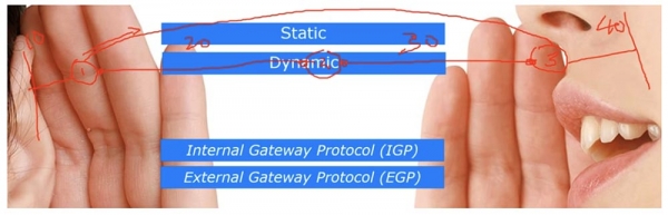
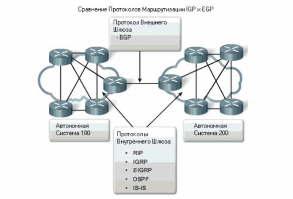
There are two types of routing protocols: Interior Gateway Protocol (IGP) and Exterior Gateway Protocol (EGP). The first protocol operates within a single, autonomous system known as a routing domain. Imagine you have a small organization with just 5 routers. If we are only talking about communication between these routers, we are referring to IGP; however, if you use your network to connect to the internet, like ISPs do, you use EGP.
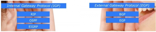
IGP uses 3 popular protocols: RIP, OSPF, and EIGRP. The CCNA curriculum only mentions the latter two protocols because RIP is outdated. It is the simplest of the routing protocols that is still used in some cases, but does not provide the necessary network security. This is one of the reasons why Cisco excluded RIP from the curriculum. However, I will still tell you about it because learning it helps understand the basics of routing.
EGP protocol classification uses two protocols: BGP and the EGP protocol itself. In the CCNA course, we will only focus on BGP, OSPF, and EIGRP. The discussion about RIP can be considered bonus information, which will be reflected in one of the video lessons.
There are also 2 types of routing protocols: Distance Vector protocols and Link State routing protocols.
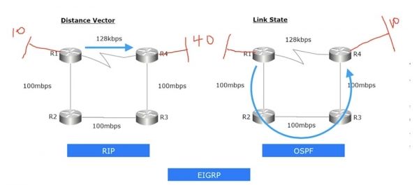
The first protocol considers distance and direction vectors. For example, I can establish a direct connection between router R1 and R4, or I can connect via the path R1-R2-R3-R4. When we talk about routing protocols that use the distance vector method, in this case, the connection will always be made through the shortest path. It does not matter that this connection will have a minimal speed. In our case, it is 128 kbps, which is much slower than the connection along the route R1-R2-R3-R4, where the speed is 100 Mbps.
Let's consider the distance vector protocol RIP. I will sketch the network 10. in front of router R1, and behind router R4 – network 40. Let's assume that there are many computers in these networks. If I want to establish a connection between network 10. R1 and network 40. R4, I will set up R1 with static routing that says: "if you need to connect to network 40., use the direct connection to router R4." At the same time, I need to manually configure RIP on all 4 routers. Then R1's routing table will automatically indicate that if network 10. wants to connect to network 40., it should use the direct connection R1-R4. Even if a detour is faster, the Distance Vector protocol will still choose the shortest path with the least transmission distance.
OSPF is a link state routing protocol that always looks at the condition of the network segments. In this case, it evaluates the speed of the links, and if it sees that the traffic speed over the link R1-R4 is very low, it will choose the path with higher speed R1-R2-R3-R4, even if its length exceeds the shortest path. Thus, if I configure the OSPF protocol on all routers, when trying to connect network 40. with network 10., the traffic will be sent via the route R1-R2-R3-R4. So, RIP is a distance vector protocol, while OSPF is a link state routing protocol.
There is another protocol – EIGRP, a proprietary routing protocol from Cisco. Speaking of networking devices from other manufacturers, for example, Juniper, they do not support EIGRP. It is an excellent routing protocol that is much more efficient than RIP and OSPF, but it can only be used in networks based on Cisco devices. Later, I will explain in more detail what makes this protocol so good. For now, I will note that EIGRP combines features of distance-vector protocols and link-state routing protocols, making it a hybrid protocol.
In the next video lesson, we will delve into Cisco routers, and I will tell you a bit about the Cisco IOS operating system, which is designed for both switches and routers. I hope that in lessons 19 or 20, we will start a detailed study of routing protocols, and I will demonstrate how to configure Cisco routers using small networks.
Thank you for staying with us. Do you enjoy our articles? Would you like to see more interesting materials? Support us by placing an order or recommending us to your friends. 30% discount for Habr users on a unique entry-level server designed by us for you: (options available with RAID1 and RAID10, up to 24 cores and up to 40GB DDR4).
Dell R730xd for half the price? Only with us in the Netherlands! Dell R420 — 2x E5-2430 2.2GHz 6C 128GB DDR3 2x960GB SSD 1Gbps 100TB — from $99! Read about how
Source: habr.com
