

Today we will discuss static routing and cover three topics: what static routing is, how it is configured, and what its alternatives are. You see the network topology, which includes a computer with the IP address 192.168.1.10 connected via a switch to a gateway, or a router. This connection uses the router's port f0/0 with the IP address 192.168.1.1.
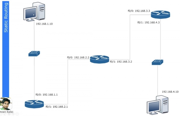
The second port of this router f0/1 with the IP address 192.168.2.1 is connected to port f0/0 of another router, which has the address 192.168.2.2. The second router is connected via port f0/1 with address 192.168.3.2 to the third router, which uses port f0/0 with the IP address 192.168.3.3 for this connection.
Finally, the third router is connected to the second switch through port f0/1 with the address 192.168.4.3, and the switch is connected to the second computer with the IP address 192.168.4.10.
If you know how to divide subnets by IP addresses, then identify that the segment from the first computer to the first router belongs to one subnet, the segment between the first and second routers belongs to the second subnet, the segment between the second and third routers belongs to the third subnet, and the segment between the third router and the second computer belongs to the fourth subnet. Thus, we have 4 different subnets.
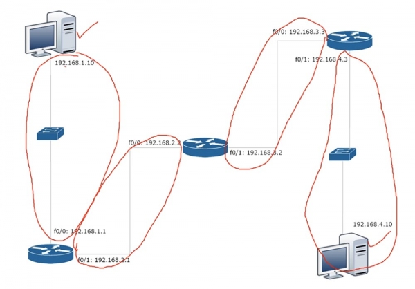
If computer 192.168.1.10 wants to communicate with computer 192.168.4.10, then it must first send its data to the gateway 192.168.1.1. It creates a frame that includes the source and destination IP addresses, source and destination MAC addresses, and sends it to the router. The router drops the level 2 information, meaning the MAC addresses, and looks at the level 3 information. Knowing that the data is addressed to a device with the IP address 192.168.4.10, the router understands that such a device is not connected to it, so it simply needs to forward this frame further along the network. It consults its routing table and sees that data for subnet 4 needs to be sent to the device with IP address 192.168.2.2.
Similarly, the second router checks its routing table, learns that data for subnet 4 needs to be sent to the IP address 192.168.3.3, and forwards the frame to the third router. Finally, the third router checks its table, determines that subnet 4 is connected to itself, and sends the frame to the second computer.
Let's take a look at how a routing table is created. For this, we will use Cisco Packet Tracer and see how the routing concept is implemented. Here is the same network topology, and now I will assign the corresponding IP addresses to the routers, also specifying the default gateway addresses.
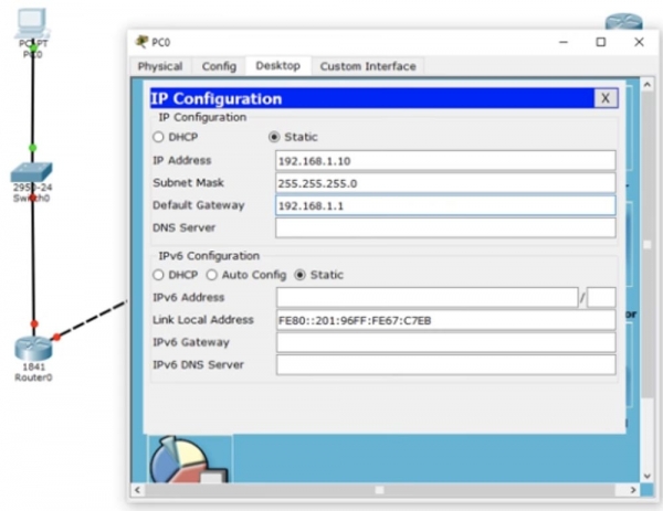
We don't do anything with the switch because it operates with default settings and uses VLAN1. Let's proceed to the settings of the first router, Router0. First, we'll assign it the hostname R1, after which we will configure the IP address and subnet mask for interface f0/0. Then we need to apply the no shutdown command. You can see how the interface marker has changed from red to green, indicating that the port has been activated in the network.
Next, we need to configure the second router port f0/1, while the hostname remains the same; we just add the IP address 192.168.2.1 and the subnet mask 255.255.255.0. There is nothing new here; it's a straightforward configuration, and you already know all the commands, so I will quickly go through the other routers. As I assign IP addresses and use the no shut command, the router ports will change color to green, indicating that the connection between devices has been established. At the same time, I am creating networks 1, 2, 3, and 4. The last octet of the router port IP address indicates the router number, while the penultimate octet indicates the network number connected to that port.
Thus, the first router will have port addresses 192.168.1.1 (first router, first network) and 192.168.2.1 (first router, second network), the second router will have 192.168.2.2 (second router, second network) and 192.168.3.2 (second router, third network), and the third router will have 192.168.3.3 (third router, third network) and 192.168.4.3 (third router, fourth network). I think this is quite easy to remember; however, in reality, addresses can be formed differently, depending on the rules adopted in your company. You should adhere to the company's rules because it will be easier for your colleague to troubleshoot your network if you structure it according to the guidelines.
So, I have finished assigning IP addresses to the router ports, and you can see that the port of the second switch has also changed color to green, as the connection between it and the second computer was established automatically.
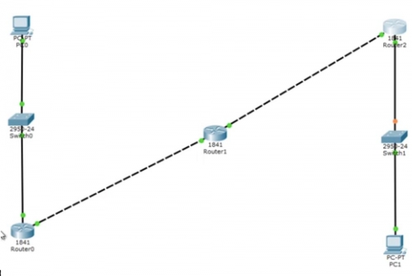
I will now call the command line terminal of the first computer and ping the second computer at the address 192.168.4.10. Let’s switch to simulation mode – now you can see the animated movement of ping packets across the network segments. I will run the ping test once more so you can closely observe what happens during the process. On the right in the table, you see ICMP, Internet Control Message Protocol – this indicates the ping. Ping is a protocol we use to check connectivity.
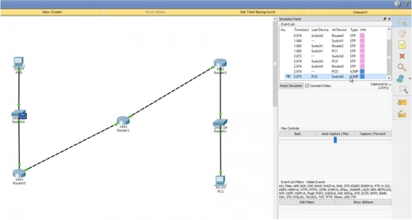
You send a test packet to another device, and if it returns it, the connection is successfully established. If you click on the ping packet in the diagram, you can view the transmission information.
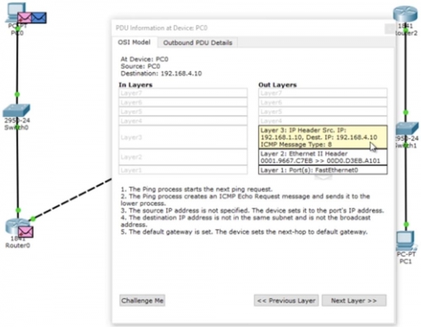
You see the data from the 3rd layer of the OSI model – the source and destination IP addresses of the ping, the 2nd layer data in the form of corresponding MAC addresses, and the 1st layer data indicating the port (or ports) – this is FastEthernet0. You can also look at the format of the ping frame: header, type, and body of the packet.
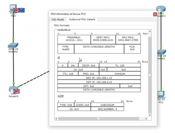
The frame is directed to the switch, which analyzes the MAC addresses and sends it further through the network to the router. The router sees the IP address 192.168.4.10 and drops the packet because it does not recognize that address. Let’s see what happens in real-time by returning to the ping in the command line window.
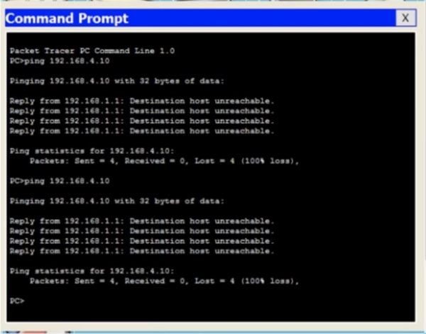
You can see that all 4 packets were lost in the attempt to ping the computer at 192.168.4.10 – the response from the router 192.168.1.1 indicates that the destination host is unreachable. Let’s return to the router’s command line interface and enter the command show ip route. You see the most important part – the routing table, and the command I entered is one of the basic Cisco routing commands. At the moment, this table contains 2 entries. At the top of the table is a list of abbreviations used, from which it is clear that the letter C indicates connections. The first entry indicates that the network 192.168.1.0/24 is directly connected to port FastEthernet0/0, while the network 192.168.2.0/24 is directly connected to port FastEthernet0/1. This means that currently, the router only knows about these two networks.
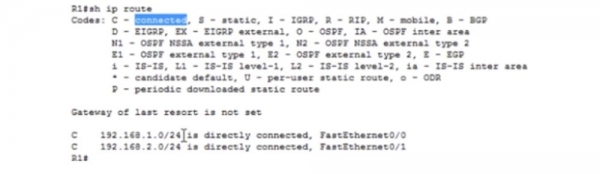
The value 192.168.1.0/24 is a network identifier. When we created subnets, we simultaneously created their identifiers. These identifiers tell the router that all devices with IP addresses ranging from 192.168.1.1 to 192.168.1.254 are located within this subnet. Thus, all these devices should technically be accessible to the router, as it is connected to this network.
If the identifier ends with /24, it means that all devices in this network from 1 to 254 will receive a broadcast message. So, only networks 1 and 2 are connected to this router, so it only knows about those networks. Therefore, when a ping from the address 192.168.4.10 reaches the router, it does not know that this address is reachable through the route Router0- Router1- Router2.
But as a network administrator, you know that this route is available, meaning the first router can send this packet to the second router. Therefore, you need to arrange static routing. Let's try to do this.
We will tell this router that any packet and any traffic intended for the network 192.168.4.0/24 should be sent to the second router. The command format for assigning static routing is as follows: ip route .

Now I will show you what this means. We use global configuration mode for this command on the router. I type ip route 192.168.4.0 255.255.255.0 – this means any traffic for devices in the network with an IP address from 1 to 254 in the last octet comes here, and then I type either the IP address or the port designation where this traffic should be sent. In this case, I type the interface designation f0/1, so the command looks like this: ip route 192.168.4.0 255.255.255.0 f0/1.
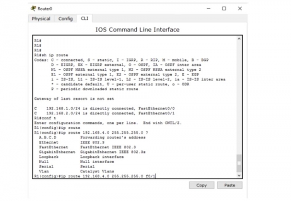
Instead of the gateway interface, I can specify its IP address, making the static routing command look like ip route 192.168.4.0 255.255.255.0 192.168.2.2.
You might wonder what is better. I believe that for broadcast networks such as Ethernet, it is preferable to specify the IP address. However, if you are using point-to-point networks like Frame Relay, it is better to use the exit interface. Later, we will discuss Frame Relay networks; for now, I will use a more suitable version of the routing command -192.168.4.0 255.255.255.0.
Now let’s take a look at the routing table using the command do show ip address. You will see that a new entry has appeared, marked with the letter S, which indicates static.
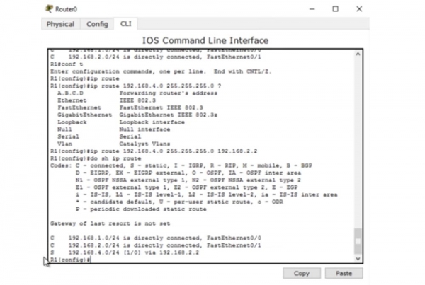
This entry indicates that if there is traffic for the network 192.168.4.0/24, it should be forwarded to the recipient through the device with the IP address 192.168.2.2. Let's return to the command line of the computer and ping the desired address once more. Now the traffic should pass through the first router and reach the second router, which should discard the packets.
In the first case, the router not only discarded the packets but also responded to the computer that the IP address 192.168.4.10 is unavailable. However, the second router can only respond to the first router from which it received the traffic. Let’s take a look at the routing table of the second router. It states that Router1 only knows about networks 2 and 3 and knows nothing about network 4, where it should send the packets from the first computer. It would send back a message indicating that the destination host is unavailable, but it doesn’t know how to reach the computer that sent those packets because it knows nothing about network 1. That’s why instead of an unavailable host message, we received a Request timed out message. Different network devices have different TTL values, so when IP packets reach this value, they are discarded. During this process, a countdown occurs – one hop is made, and the TTL counter changes from 16 to 15, then from 15 to 14, and so on, until the TTL value reaches 0 and the packet is destroyed.
This is how the mechanism preventing IP packet looping works. If a device does not receive a request within the set time, the system issues a message like this one. Let’s move on to the settings of the second router and show it how to reach the fourth subnet. For this, I will use the command ip route 192.168.4.0 255.255.255.0 192.168.3.3. Now the corresponding entry has appeared in the routing table, which we called with the command do show ip route.
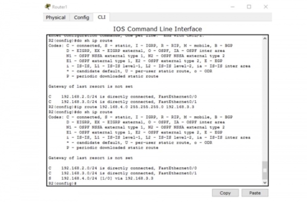
Now Router1 knows how to send traffic to the destinations in the fourth subnet. It forwards it to the third router. The third router, Router2, which is connected to network 4, definitely knows how to send the packet to the second computer.
What will happen if I send a ping again? After all, now all the network devices know how to reach the second computer. Will pinging the IP address 192.168.4.10 be successful? No, it won’t!
As I mentioned, ICMP is a protocol for two-way communication, so if someone sends ping packets, they should be returned. Routing means that each network device must not only know how to send a message to someone but also how to deliver a response back to the request sender. So, the packet sent by the first computer successfully reached the second computer. The second computer thinks, 'Great, I received your message and now need to send you a response.' This response, addressed to the device with the IP address 192.168.1.10, reaches the Router2. The third router sees it needs to send the packet to the first subnet, but its routing table only contains entries for the third and fourth subnets. Therefore, we need to create a static route using the command ip route 192.168.1.0 255.255.255.0 192.168.3.2. This command tells that the traffic intended for the network identified as 192.168.1.0 should be sent to the second router with the IP address 192.168.3.2.
What will happen after this? The second router knows about networks 2, 3, and 4, but knows nothing about the first network. Therefore, we need to go into the settings of the second router, Router1, and use the command ip route 192.168.1.0 255.255.255.0 192.168.2.1, which specifies that traffic for network 1 should be sent through network 2 to the first router, Router0.
After this, the packet reaches the first router, which is aware of the device 192.168.1.10 because the first network of this computer is connected to this router's port. Note that the first router now knows nothing about network 3, and the third router knows nothing about the second network. This could create a problem because these routers are unaware of the existence of intermediate subnets.
I ping the address 192.168.4.0 once again, and you can see that this time the ping was successful. The packets traveled the entire route from the first to the second computer and a response returned to the sender. The command window shows that each of the 4 response packets from 192.168.4.0 consists of 32 bytes, with a TTL of 125 ms, and the ping success rate is 100%. This means that the source received a reply from the destination host. Thus, even if the devices are unaware of some intermediate networks, it does not matter if they operate on the principle of 'final sender – final receiver'. The first computer knows how to reach the second computer, and the second knows how to reach the first.
Let's consider another situation. So, the first computer can successfully communicate with the second computer, with traffic passing through all these devices. Let's see if PC0 can connect to the third router, Router2, at address 192.168.3.3 – this is the port of network 3 of the third router. The ping shows that this is impossible – the destination host is unreachable.
Let's see what the reason is. Opening the routing table of the first router, we see that it only knows about 3 networks – the first, the second, and the fourth, but knows nothing about the third network. Therefore, if I want to connect to this network, a static route needs to be set for it.
Thus, we have looked at how to set up static routing for three routers. If you have 10 routers and 50 different subnets, manually configuring static routing will take a very long time. This is why we need dynamic routing.
I will now delete all the routes I created. To do this, I will sequentially call the routing tables of all the routers and prepend the word 'no' to the beginning of each static routing entry, thereby using the negation command. Now we can consider what dynamic routing is.
For dynamic routing, I need to activate the RIP protocol, which is a very fast protocol. But today, we will not discuss RIP; our topic is static routing, and I wanted to show you how meticulous and tedious this process is. I will still quickly demonstrate how RIP works, which we will discuss in detail in the next lesson.
Using the first router as an example, I will use the command router rip, then enter ver 2 to specify the protocol version, and then list the networks for which to use the dynamic routing protocol on separate lines: 192.168.1.0, 192.168.2.0. After that, I will move on to the second router and do the same. Technically, I am simply specifying the networks connected to this device, so for the second router, I will specify 192.168.2.0 and 192.168.3.0, and for the third router, after the command rip ver 2, I will use addresses 192.168.3.0 and 192.168.4.0. Then I will go back to the first router and check the routing table.
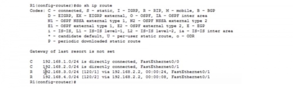
You can see that all networks magically appeared in it; the first two are those directly connected to the router, while the other two are those that are connected via the dynamic routing protocol RIP. The same situation is observed in the routing tables of the second and third routers. If I connect networks 5. and 6. to the second router, all devices using RIP will learn about these new networks. This is the advantage of dynamic routing.
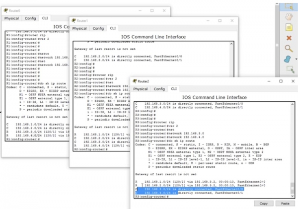
If I ping the second computer now, the connection will work without issues. I can ping the third router, and the ping will be successful because the first router, thanks to RIP, knows about all devices in all networks. The second and third routers will have similar 'knowledge'. I'm not saying that RIP is the best protocol, but it can effectively perform many tasks. For now, I just want you to understand what routing is, how it works, what a routing table is, and its significance.
Regardless of whether you use static or dynamic routing, the role of protocols is to fill the routing table. This table must know about all routes to all devices on the network so that one device can connect to another.
So today you learned that routing is the process that ensures the creation of route entries in routing tables so that a router can make decisions about sending traffic across the network.

Thank you for staying with us. Do you enjoy our articles? Would you like to see more interesting materials? Support us by placing an order or recommending us to your friends. 30% discount for Habr users on a unique entry-level server designed by us for you: (options available with RAID1 and RAID10, up to 24 cores and up to 40GB DDR4).
Dell R730xd for half the price? Only with us in the Netherlands! Dell R420 — 2x E5-2430 2.2GHz 6C 128GB DDR3 2x960GB SSD 1Gbps 100TB — from $99! Read about how
Source: habr.com
