

Today, we will take a closer look at some aspects of routing. Before we begin, I want to address a student question about my social media pages. On the left, I have placed links to our company's pages, and on the right – to my personal pages. I would like to point out that I do not add someone as a friend on Facebook unless I know them personally, so please do not send me friend requests.

You can simply follow my Facebook page to stay updated on all events. I respond to messages on my LinkedIn account, so feel free to contact me there, and of course, I am most active on Twitter. Below this video lesson, you’ll find links to all 6 social networks, so you can make use of them.
As usual, today we will cover three topics. The first is an explanation of the essence of routing, where I will tell you about routing tables, static routing, and so on. Then we will look at Inter-Switch routing, which explains how routing occurs between two switches. At the end of the lesson, we will become acquainted with the concept of Inter-VLAN routing, where one switch interacts with multiple VLANs and how these networks connect. This is a very interesting topic, and you might want to review it several times. There is also another interesting topic called Router-on-a-Stick.
So, what is a routing table? It is a table on which routers base their routing decisions. You can see what a typical routing table of Cisco routers looks like. Each computer running Windows also has a routing table, but that’s another topic.
The letter R at the beginning of the line indicates that the route to the network 192.168.30.0/24 is provided by the RIP protocol, C means that the network is directly connected to the router’s interface, S stands for static routing, and the dot after this letter shows that this route is a candidate default for performing static routing. There are several types of static routes, and today we will become familiar with them.
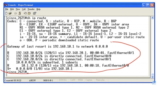
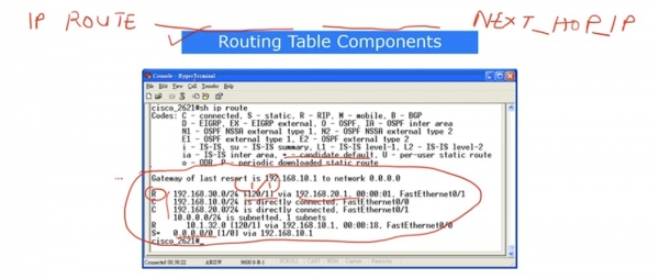
Let's consider the first network 192.168.30.0/24 as an example. In the line, you see two numbers in square brackets separated by a slash, which we have already discussed. The first number, 120, is the administrative distance that indicates the level of trust in this route. Suppose there is another route to this network in the table, designated by the letter C or S, with a lower administrative distance, for example, 1, as in static routing. In this table, you will not find two identical networks unless we use a mechanism like load balancing, but let's assume we have two entries for the same network. If you see a smaller number, it means that this route deserves more trust, and conversely, the larger the value of the administrative distance, the less trust this route deserves. Next in the line, it states through which interface the traffic should be sent – in our case, it is port 192.168.20.1 FastEthernet0/1. Here are the components that make up the routing table.
Now let's talk about how the router makes routing decisions. I mentioned the default candidate earlier and will explain what this means. Suppose the router receives traffic for network 30.1.1.1, which is missing from the routing table. Normally, the router would simply discard this traffic, but if there is an entry for a default candidate in the table, it means that everything the router doesn't know will be directed to the default candidate. In this case, the entry indicates that traffic coming for an unknown network to the router should be forwarded through port 192.168.10.1. Thus, traffic for network 30.1.1.1 will follow the route identified as the default candidate.
When a router receives a request to establish a connection with a certain IP address, it first checks if that address is contained in a specific route. Therefore, when it receives traffic for the network 30.1.1.1, it will first check to see if its address is in a specific entry in the routing table. Thus, if the router receives traffic for 192.168.30.1, it will check all entries and see that this address is contained within the address range of the network 192.168.30.0/24, after which it will send the traffic along this route. If no specific entries are found for network 30.1.1.1, the router will send the traffic destined for it via the candidate default route. This is how decisions are made: first, specific route entries are checked in the table, and then the candidate default route is used.
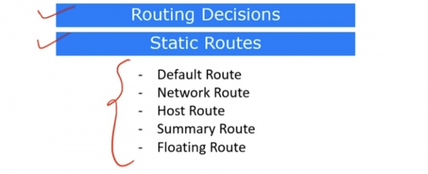
Now, let's look at different types of static routes. The first type is a default route.
As I mentioned, if the router receives traffic addressed to an unknown network, it will send it via the default route. The notice that a default route is set is indicated by the entry Gateway of last resort is 192.168.10.1 to network 0.0.0.0, meaning 'The gateway of last resort for network 0.0.0.0 has an IP address of 192.168.10.1.' This route is listed in the last line of the routing table, labeled with the letter S followed by a dot.
This parameter can be configured from global configuration mode. For a regular route using the RIP protocol, you need to enter the command ip route, specifying the identifier of the corresponding network, in our case 192.168.30.0, and the subnet mask 255.255.255.0, then specify 192.168.20.1 as the next hop. However, when setting the default route, you do not need to specify the network identifier and mask; you simply enter ip route 0.0.0.0 0.0.0.0, which means that instead of the subnet mask address, you again enter four zeros, and at the end of the line, you indicate the address 192.168.20.1, which will represent the default route.
The next type of static route is a Network Route. To set a network route, you need to specify an entire network, meaning using the command ip route 192.168.30.0 255.255.255.0, where the 0 at the end of the subnet mask signifies the entire range of 256 addresses for the /24 network, and specify the IP address of the next hop.
Now I will draw a template depicting the default route installation command and network route. It looks as follows:
ip route first part of the address second part of the address .
For the default route, both the first and second parts of the address will consist of 0.0.0.0, while for the network route, the first part represents the network identifier and the second - the subnet mask. Next will be the IP address of the network to which the router has decided to make the next hop.
For host route configuration, the host route uses the IP address of a specific host. In the command template, this will be the first part of the address, in our case 192.168.30.1, which points to a specific device. The second part is the subnet mask 255.255.255.255, which also indicates the IP address of a specific host, not an entire /24 network. Then you need to specify the next hop IP address. This is how you can establish a host route.
Summary route is an aggregate route. You remember that we already discussed the issue of route summarization when we have a range of IP addresses. Let's take the first network 192.168.30.0/24 and suppose we have a router R1 connected to network 192.168.30.0/24 with four IP addresses: 192.168.30.4, 192.168.30.5, 192.168.30.6, and 192.168.30.7. The slash 24 indicates that there are a total of 256 valid addresses in this network; however, in this case, we only have 4 IP addresses.
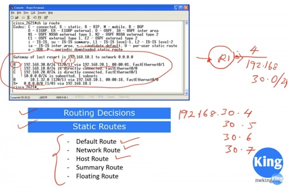
If I state that all traffic for network 192.168.30.0/24 should be routed through this route, that would be misleading because an IP address like 192.168.30.1 may not be accessible through this interface. Therefore, in this case, we cannot use 192.168.30.0 as the first part of the address, but must specify which specific addresses will be available. In this case, 4 specific addresses will be accessible through the right interface, while the other addresses of the network will be accessible through the left interface of the router. This is why we need to configure a summary or aggregate route.
From the principles of route summarization, we remember that in one subnet the first three octets of the address remain unchanged, and we need to create a subnet that encompasses all four addresses. For this, we need to specify the first part of the address as 192.168.30.4, and in the second part, use 255.255.255.252 as the subnet mask, where 252 means that this subnet contains 4 IP addresses: .4, .5, .6, and .7.
If your routing table contains two entries: a RIP route for the network 192.168.30.0/24 and a summary route 192.168.30.4/252, according to routing principles, the preferred route for specific traffic will be the Summary route. Everything that does not relate to this specific traffic will use the Network route.
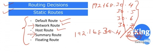
Here is what a summary route looks like – you aggregate several specific IP addresses and create a separate route for them.
In the group of static routes, there is also something called a 'floating route'. This is a backup route. It is used in case of issues with the physical connection of the static route, which has an administrative distance of 1. In our example, this is the route through the IP address 192.168.10.1 in the last line of the routing table, and if this route is disrupted at the physical level, the backup floating route is used.
To activate the backup route, at the end of the command line instead of the next hop IP address, which by default has a value of 1, another hop value, such as 5, is specified. The floating route is not listed in the routing table because it only comes into play when the static route becomes unavailable due to a failure.
If you didn't understand something from what I just explained, please watch the video again. If you still have questions, feel free to send me an email, and I will explain everything to you.
Now let's consider Inter-Switch routing. On the left side of the diagram is a switch serving the blue network of the sales department. On the right is another switch that operates solely with the green network of the marketing department. In this case, two independent switches are used, each serving different departments, as this topology does not utilize a shared VLAN network.
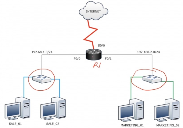
If you need to establish a connection between these two switches, that is, between the two different networks 192.168.1.0/24 and 192.168.2.0/24, a router must be used. This way, these networks can exchange packets and access the internet through router R1. If we used VLAN1 by default for both switches, connected by physical cables, they could communicate with each other. However, as this is technically impossible due to the separation of networks belonging to different broadcast domains, a router is necessary for their communication.
Assuming that each switch has 16 ports. In our case, we do not use 14 ports, as each department has only 2 computers. Therefore, it is optimal to use VLANs in this scenario, as shown in the next diagram.
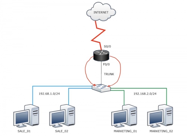
In this case, the blue network VLAN10 and the green network VLAN20 each have their own broadcast domain. The VLAN10 network is connected via cable to one port on the router, while the VLAN20 network connects to another port, with both cables originating from different switch ports. It seems that with this great solution, we have established communication between the networks. However, since the router has a limited number of ports, we are extremely inefficiently utilizing the capabilities of this device by occupying them in this way.
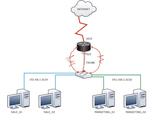
There is a more efficient solution – a 'router on a stick.' In this case, we connect a switch port trunk to one of the router's ports. We have already mentioned that by default, the router does not understand encapsulation according to the .1Q standard, so a trunk must be used to establish communication with it. The following occurs.
The blue VLAN10 network sends traffic through the switch to the F0/0 router interface. This port is divided into sub-interfaces, each of which has one IP address located in the address range of either the 192.168.1.0/24 network or the 192.168.2.0/24 network. This creates some ambiguity, as two different networks require two different IP addresses. Therefore, while the trunk between the switch and the router is created on one physical interface, we need to create two sub-interfaces for each VLAN. Thus, one sub-interface will serve the VLAN10 network, and the other will serve VLAN20. For the first sub-interface, we need to select an IP address from the 192.168.1.0/24 address range, and for the second, from the 192.168.2.0/24 range. When VLAN10 sends a packet, one IP address will be the gateway, and when VLAN20 sends a packet, the second IP address will be used as the gateway. Meanwhile, the 'router on a stick' will make a decision regarding the traffic flow from each of the 2 computers belonging to different VLANs. In simpler terms, we are dividing one physical interface of the router into two or more logical interfaces.
Let's see how this looks in the Packet Tracer program.
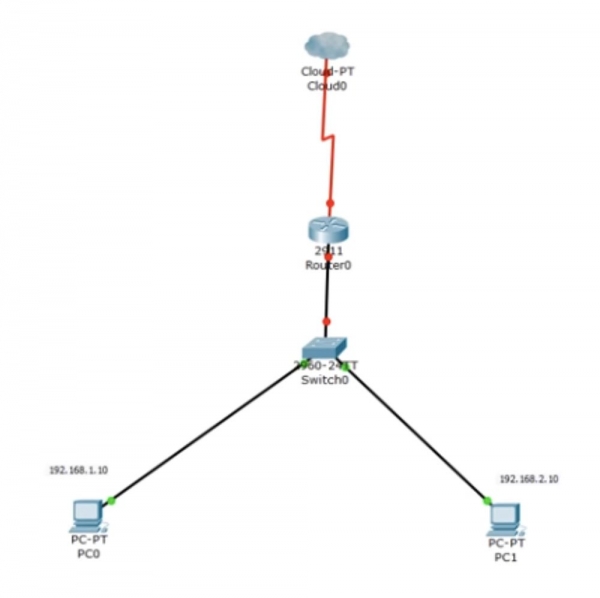
I simplified the diagram a bit, so we have one computer PC0 with the IP address 192.168.1.10 and a second computer PC1 with the address 192.168.2.10. When configuring the switch, I allocate one interface for VLAN10 and another for VLAN20. I access the CLI console and enter the command show ip interface brief to ensure that the FastEthernet0/2 and 0/3 interfaces are enabled. Then, I check the VLAN database and see that currently all switch interfaces are part of the default VLAN. Next, I sequentially enter the commands config t and int f0/2 to call up the port connected to the sales department's VLAN.
Next, I use the command switchport mode access. The access mode is used by default, so I just type this command. After that, I type switchport access VLAN10, and the system responds that since such a network does not exist, it will create VLAN10 itself. If you want to create a VLAN manually, for example, VLAN20, you need to type the command vlan 20, after which the command prompt will switch to virtual network settings, changing its header from Switch(config) # to Switch(config-vlan) #. Next, you need to assign the created network the name MARKETING using the command name . Then, we configure interface f0/3. I sequentially enter the commands switchport mode access and switchport access vlan 20, after which the network is connected to this port.
Thus, you can configure the switch in two ways: the first is by using the command switchport access vlan 10, after which the network is created automatically on this port; the second is when you first create the network, and then bind it to a specific port.
Similarly, the same can be done with VLAN10. I will go back and repeat the manual setup process for this network: I will enter global configuration mode, type the command vlan 10, then assign it the name name SALES, and so on. Now, I will show you what happens if you do not do this, that is, let the system create the VLAN network itself.
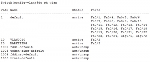
You can see that we have both networks, but the second one, which we created manually, has its own name MARKETING, while the first network VLAN10 received a default name VLAN0010. I can fix this if I now enter the command name SALES in global configuration mode. Now you see that after this, the first network changed its name to SALES.
Now let's go back to Packet Tracer and check if computer PC0 can communicate with computer PC1. To do this, I will open the command line terminal of the first computer and send a ping to the address of the second computer.
We see that the ping was unsuccessful. The reason is that PC0 sent an ARP request for 192.168.2.10 via the gateway 192.168.1.1. In this case, the computer essentially asked the switch who 192.168.1.1 is. However, the switch has only one interface for the VLAN10 network, and the received request cannot go anywhere – it arrives at this port and dies here. The computer doesn't receive a response, which is why the ping failure indicates a timeout. No response was received because there are no other devices in the VLAN10 network besides PC0. Moreover, even if both computers were part of the same network, they still wouldn't be able to communicate, as they have different IP address ranges. To make this scheme work, a router needs to be used.
However, before I show how to engage the router, I will make a small digression. I will connect the Fa0/1 port of the switch to the Gig0/0 port of the router with one cable, and then add another cable that will connect to the Fa0/4 port of the switch and the Gif0/1 port of the router.
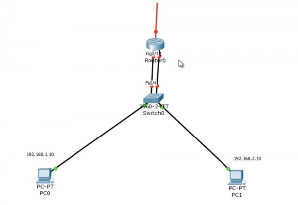
I will bind the VLAN10 network to the f0/1 port of the switch, for which I will enter the commands int f0/1 and switchport access vlan10, and the VLAN20 network – to the f0/4 port, using the commands int f0/4 and switchport access vlan 20. If we now look at the VLAN database, we can see that the SALES network is bound to the Fa0/1 and Fa0/2 interfaces, while the MARKETING network is bound to the Fa0/3 and Fa0/4 ports.
Let's go back to the router and enter the settings for the g0/0 interface, type the command no shutdown, and assign it an IP address: ip add 192.168.1.1 255.255.255.0.
We will similarly configure the g0/1 interface, assigning it the address ip add 192.168.2.1 255.255.255.0. Next, we will ask to show us the routing table, which now has entries for networks 1.0 and 2.0.
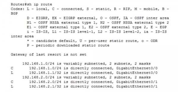
Let's see if this scheme works. We will wait for both the switch and router ports to turn green and repeat the ping to the IP address 192.168.2.10. As you can see, everything worked!
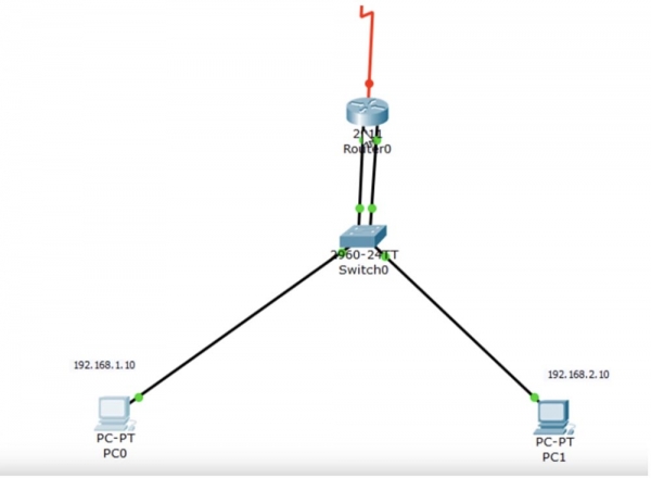
Computer PC0 sends a request via the ARP protocol to the switch, the switch addresses it to the router, and the router sends its MAC address back to the computer. After that, the computer sends a ping packet back along the same path. The router knows that the VLAN20 network is connected to its g0/1 port, so it sends it to the switch, which forwards the packet to the destination – PC1.
This scheme works, but it is inefficient as it uses 2 router interfaces, meaning we are not utilizing the router's technical capabilities effectively. Therefore, I will show how the same thing can be achieved using a single interface.
I will remove the scheme with two cables and restore the previous connection between the switch and router with one cable. The switch's f0/1 interface should become a trunk port, so I return to the switch settings and use the command switchport mode trunk for this port. We will no longer use port f0/4. Next, we use the command show int trunk to check if the port is configured correctly.
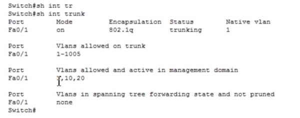
We can see that port Fa0/1 is operating in trunk mode using the 802.1q encapsulation protocol. Let's look at the VLAN table – we see that interface F0/2 is occupied by the sales department network VLAN10, and interface f0/3 is for the marketing network VLAN20.
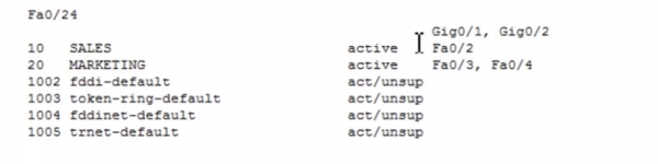
At the same time, the switch is connected to the g0/0 port of the router. In the router settings, I use the commands int g0/0 and no ip address to remove the IP address from this interface. However, this interface is still operational; it is not in a shutdown state. As you may recall, the router needs to receive traffic from both networks – 1.0 and 2.0. Since the switch is connected to the router via a trunk, traffic will come to the router from both networks. But what IP address should be assigned to the router's interface in this case?
G0/0 is a physical interface that, by default, does not have any IP address. Therefore, we use the concept of a logical sub-interface. If I enter int g0/0, the system will provide two possible command options: a slash / or a dot. The slash is used when configuring modular interfaces like 0/0/0, while the dot is used when you have a sub-interface.
If I enter int g0/0. ?, the system will return a range of possible logical sub-interface numbers for GigabitEthernet, which are indicated after the dot: . This range contains over 4 billion numbers, meaning that this many logical sub-interfaces can be created.

I will indicate the number 10 after the dot, which will represent VLAN10. Now we have entered the subinterface settings, as evidenced by the change of the CLI settings line heading to Router (config-subif) #, specifically regarding the subinterface g0/0.10. Now I need to assign it an IP address, for which I use the command ip add 192.168.1.1 255.255.255.0. Before setting this address, encapsulation must be performed so that the subinterface we created knows which encapsulation protocol to use — 802.1q or ISL. I type the word encapsulation in the line, and the system provides possible parameter options for this command.

I use the command encapsulation dot1Q. Technically, entering this command is not strictly necessary, but I type it to indicate to the router which protocol should be applied for VLAN functionality, as it is currently operating as a switch servicing VLAN trunking. This command tells the router that all traffic should be encapsulated using the dot1Q protocol. Next, in the command line, I need to indicate that this encapsulation pertains to the VLAN10 network. The system shows us the used IP address, and the interface for the VLAN10 network begins to operate.
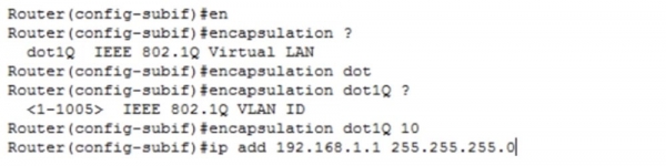
In the same way, I configure interface g0/0.20. I create a new subinterface, set the encapsulation protocol, and assign the IP address using the command ip add 192.168.2.1 255.255.255.0.
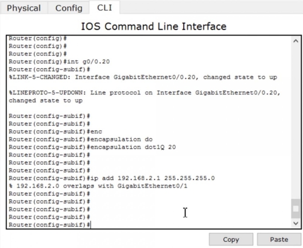
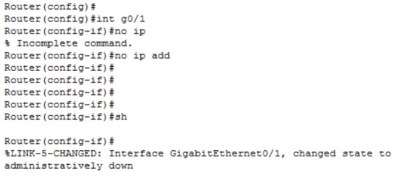
At this point, I definitely need to remove the IP address from the physical interface because the physical interface and the logical subinterface currently have the same address for the VLAN20 network. To do this, I sequentially type the commands int g0/1 and no ip address. Then I disable this interface because we no longer need it.
Next, I return to interface g0/0.20 and assign it an IP address using the command ip add 192.168.2.1 255.255.255.0. Now everything will definitely work.
Now I use the command show ip route to view the routing table.
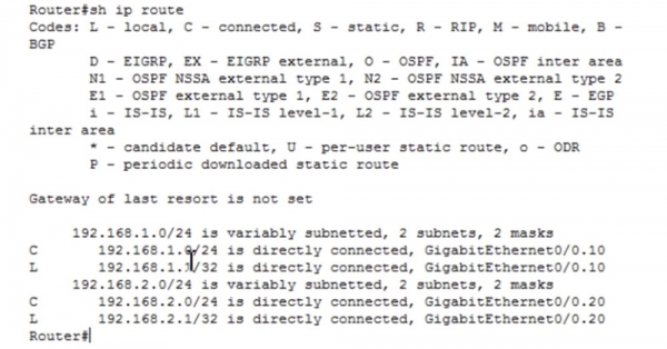
We see that the network 192.168.1.0/24 is directly connected to the subinterface GigabitEthernet0/0.10, and the network 192.168.2.0/24 is directly connected to the subinterface GigabitEthernet0/0.20. Now I will return to the command line terminal of PC0 and ping PC1. In this case, the traffic goes to the router port, which translates it to the corresponding subinterface and sends it back through the switch to the PC1 computer. As you can see, the ping was successful. The first two packets were dropped because switching between router interfaces takes some time, and the devices need to learn the MAC addresses, but the other two packets successfully reached their destination. This is how the concept of 'router on a stick' works.

Thank you for staying with us. Do you enjoy our articles? Would you like to see more interesting materials? Support us by placing an order or recommending us to your friends. 30% discount for Habr users on a unique entry-level server designed by us for you: (options available with RAID1 and RAID10, up to 24 cores and up to 40GB DDR4).
Dell R730xd for half the price? Only with us in the Netherlands! Dell R420 — 2x E5-2430 2.2GHz 6C 128GB DDR3 2x960GB SSD 1Gbps 100TB — from $99! Read about how
Source: habr.com
